Engineering task and calculation objective
The KOND module calculates shell-and-tube condensers for pure vapors according to the methods of the VDI Heat Atlas (VDI-Wärmeatlas), the standard German reference for heat exchanger design. A condenser can be divided into up to three zones: the desuperheating zone, in which superheated vapor is cooled to saturation temperature, the actual condensation zone with film condensation, and the subcooling zone, in which the condensate is cooled below the boiling temperature. Heat transfer, area and pressure drop are balanced separately for each zone.
Anyone who condenses steam-turbine exhaust, knocks down vapors from evaporators or columns, designs refrigerant condensers or recovers process vapors needs this condenser calculation. The module covers both condensation in the shell space on horizontal or vertical tubes and condensation inside the tubes; the cooling medium flows on the respective other side. For shell-side condensation on horizontal tubes, condensate subcooling is not calculated, because the condensate drips off there and wets the tubes only briefly.
The scope of validity is deliberately limited: only pure substances are treated — with mixtures, the condensation temperature shifts along the dew line and diffusion resistances reduce the heat transfer, which requires dedicated methods. The calculation is likewise restricted to condensers with a single tube-side pass.
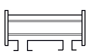
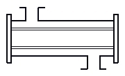
Standard and calculation basis: VDI Wärmeatlas
Calculation workflow
- Define the task and configuration: The vapor flow rate, inlet state (saturated or superheated), operating pressure and the configuration are defined: condensation in the shell space on horizontal or vertical tubes, or condensation inside the tubes. Added to this are the tube-bundle geometry with tube diameter, tube pitch and baffles, plus the cooling-water data.
- Heat balance and zone division: From the streams and states, the heat duties of the zones are determined: desuperheating of the superheated vapor, enthalpy of condensation at saturation temperature and, where applicable, subcooling of the condensate. Each zone receives its own mean temperature difference to the cooling medium.
- Calculate the condensing-side heat transfer: In the condensation zone, the film-condensation heat transfer coefficient is calculated according to Nusselt's falling-film theory with the extensions of the VDI Heat Atlas: for horizontal bundles, with the influence of the condensate running from tube row to tube row and the vapor shear stress; for in-tube condensation, with flow-dependent approaches for annular and stratified flow.
- Coolant-side heat transfer and overall coefficient: On the coolant side, the heat transfer for forced convection in the tube or in the baffled shell space is determined. Together with the wall resistance and fouling resistances, the overall heat transfer coefficient of each zone results.
- Determine the area requirement and pressure drops: From heat duty, overall heat transfer coefficient and mean temperature difference, the area requirement per zone follows; the sum is compared with the available exchange area. In parallel, the pressure drops on both sides are calculated — important on the vapor side, because the pressure drop lowers the saturation temperature and thus the driving temperature difference.
- Rating and assessment: The design is checked iteratively: area margin, condensate outlet state, cooling-water temperature rise and flow velocities must lie within permissible ranges. If necessary, tube count, tube length or baffle spacing are adjusted.
Input quantities
| Quantity | Symbol | Unit |
|---|---|---|
| Mass flow | mi ma | kg/s |
| Mass flow | mi ma | kg/s |
| Saturation temperature | ϑS,i ϑS,a | °C |
| Saturation temperature | ϑS,i ϑS,a | °C |
| Density | ρi ρa | kg/m³ |
| Density | ρi ρa | kg/m³ |
| Specific heat capacity | cpi cpa | J/(kg·K) |
| Specific heat capacity | cpi cpa | J/(kg·K) |
| Inlet temperature | ϑei ϑea | °C |
| Outlet temperature | ϑai ϑaa | °C |
| Inlet temperature | ϑei ϑea | °C |
| Outlet temperature | ϑai ϑaa | °C |
| Heat duty | Qi Qa | W |
| Heat duty | Qi Qa | W |
| Heat loss | Qv | W |
| Heat transfer coefficient (inside) | αi | W/(m²·K) |
| Heat transfer coefficient (outside) | αa | W/(m²·K) |
| Thermal conductivity of tube material | λ | W/(m·K) |
| Total fouling resistance | f | m²·K/W |
| Required heat transfer area | A | m² |
| Logarithmic mean temperature diff. LMTD | Δϑ | K (diff) |
| Overall heat transfer coefficient | k | W/(m²·K) |
| Tube outside diameter Tube wall thickness | da si | m |
| Tube inside diameter | di | m |
Calculated results
| Quantity | Symbol | Unit |
|---|---|---|
| Number of tubes | N | - |
| Tube length between the tubesheets | l la | m |
| Heat transfer area | A Aa | m² |
| Heat transfer area | A Aa | m² |
| Tube length between the tubesheets | l la | m |
| Heat transfer area | A Aa | % |
| Number of tubes U-tubes | N | – |
Calculation options
No tubes in window
No · Yes
Countercurrent flow / Cocurrent flow?
Countercurrent flow · Cocurrent flow
Frequently asked questions
Why is the method restricted to pure vapors?
With a pure substance, the vapor condenses at constant saturation temperature and the heat transfer is determined solely by the condensate film. With mixtures, the condensation temperature drops along the dew line, and a diffusion layer enriched in light ends or inert gas builds up in front of the phase interface, degrading the heat transfer considerably. Such cases require coupled heat and mass transfer methods (e.g. Silver/Bell-Ghaly) and lie outside this module.
Why is no subcooling calculated for shell-side condensation on horizontal tubes?
On horizontal tubes, the condensate runs off as a film and drips from tube to tube; it collects at the bottom of the shell without flowing along cooled surfaces in a defined way. Deliberate subcooling would only be achievable with design measures such as a flooded tube section or a separate aftercooler. The method therefore does not report subcooling for this configuration.
What effect do even small inert-gas fractions in the vapor have?
Inert gases accumulate at the phase interface and form a diffusion barrier through which the vapor must diffuse to the cold wall. Even a few volume percent of non-condensable gases can reduce the heat transfer coefficient to a fraction. In practice, vent connections must therefore be provided at the points of inert-gas accumulation; the pure-vapor design applies only to well-vented systems.
Why is the vapor-side pressure drop particularly critical in condensers?
The pressure drop lowers the saturation pressure and hence the condensation temperature along the flow path; the driving temperature difference to the coolant shrinks. In vacuum condensers, a seemingly moderate pressure drop of a few millibar can cost several kelvin of saturation temperature and enlarge the required area considerably. Condensers are therefore built with large vapor inlet cross-sections and low velocities on the vapor side.
What does the restriction to a single tube-side pass mean?
The calculation model represents the temperature profiles and zone boundaries for a single tube-side pass. Multi-pass units create alternating counter-current and co-current sections on the tube side, whose zone assignment can no longer be described unambiguously with this approach when condensation takes place in the shell space at the same time. Extended cell models are required for multi-pass condensers.