Engineering task and calculation objective
The flange is the connecting element of every detachable joint in pressure vessel and piping engineering: it must transfer the bolt loads through its flange ring into the shell or pipe without deforming excessively or failing. If you want to calculate a flange to AD 2000 — the German pressure vessel code — you size the required flange ring thickness to AD 2000-Merkblatt B8, building on the bolt and gasket loads from Merkblatt B7.
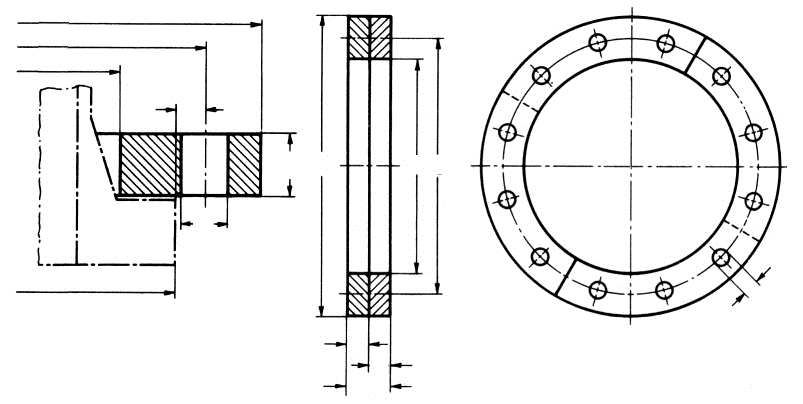
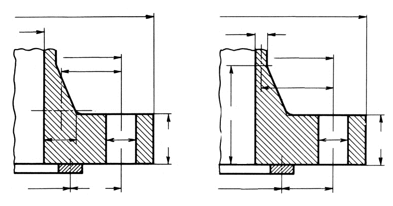
The B8 module determines the required flange ring thickness for practically all common types: welding-neck flanges and welding-neck hubs, set-on flanges and set-on hubs (including versions with hinged bolts or facing inward), loose flanges on a hub or lapped pipe end, flanges with full-face gaskets, segmented loose flanges with one ring or with offset rings, loose flanges with a segmented insert ring, and threaded (bolted-on) flanges. The type is selected with figure support; from it follow the applicable section modulus and lever arm formulas.
The bolting-up, operating and test conditions are verified: bolt load times lever arm yields the bending moment, which is compared with the section modulus of the flange cross-section — for welding-neck flanges including the contributing hub and pipe neck. The module is thus the standard route for designing equipment flanges, custom flanges and loose-flange joints to AD 2000, complete with worked verification of every load condition.
Standard and calculation basis: AD 2000 B8: 2023-05
Calculation workflow
- Select the flange type: The applicable design is chosen from the catalog of types (welding-neck flange, set-on flange, loose flange, segmented rings, threaded flange, etc.) — with display of the code figures if desired. The type determines which cross-sections carry load and where the critical sections lie.
- Take the forces from the bolt calculation: The bolt and gasket loads for the bolting-up, operating and test conditions come from the calculation to AD 2000 B7 with the corresponding gasket factors. Together with the bolt circle, gasket and inside diameters, they yield the lever arms of the individual force components.
- Form the bending moments per condition: For each condition, the bending moment acting on the critical cross-section is calculated from the forces and their lever arms: in the bolting-up condition from the bolt load to the gasket, in the operating condition from the hydrostatic end force, the ring area force and the residual gasket load.
- Determine the flange section modulus: The section modulus of the flange cross-section is calculated depending on the type; for welding-neck flanges the hub and the adjoining cylinder contribute, for loose flanges only the ring cross-section counts, and for segmented rings reductions apply. Bolt holes are accounted for via the hole deduction.
- Perform the verification and set the flange ring thickness: The actual moment is compared with the allowable moment from the flange section modulus and the design stress K/S of the respective condition. The required flange ring thickness follows from the most unfavorable condition; for construction, it is rounded up to the next practical dimension.
Input quantities
| Quantity | Symbol | Unit |
|---|---|---|
| Inside diameter | di | mm |
| Outside diameter | da | mm |
| Thickness of hub | s1 | mm |
| Thickness of tapered neck | sF | mm |
| Bolt hole diameter | dL | mm |
| Bolt circle diameter | dt | mm |
| Mean gasket diameter | dD | mm |
| Bolt load (Operation) | FSB | N |
| Bolt load (Bolting-up) | FDV | N |
| Design diameter | d2 | mm |
| Operating temperature | T | °C |
| Material | Wk | – |
| Safety factor (Operation) | S | – |
| Safety factor (bolting-up test) | S' | – |
| Nominal design strength at operating temperature | K | N/mm² |
| Nominal design strength at 20°C | K20 | N/mm² |
| Total flange height | hA | mm |
| Flange section modulus | Wb | mm³ |
| Flange section modulus | We | mm³ |
| Flange section modulus | Wb | mm³ |
| Flange section modulus | We | mm³ |
| Lever of the bolt load | a | mm |
| Lever of the bolt load | aD | mm |
| Lever of the bolt load | a | mm |
Calculated results
| Quantity | Symbol | Unit |
|---|---|---|
| Inside diameter | di | mm |
| Outside diameter | da | mm |
| Bolt hole diameter | dL | mm |
| Joint efficiency | v | – |
| Bolt circle diameter | dt | mm |
| Bolt load (Operation) | FSB | N |
| Bolt load (Bolting-up) | FDV | N |
| Operating temperature | T | °C |
| Material | Wk | – |
| Safety factor (Operation) | S | – |
| Safety factor (bolting-up test) | S' | – |
| Nominal design strength at operating temperature | K | N/mm² |
| Nominal design strength at 20°C | K20 | N/mm² |
| Calculated double flange width | b | mm |
| Auxiliary value | Z | mm³ |
| Auxiliary value | Z1 | mm³ |
| Reduced bolt hole diameter | dL' | mm |
| Flange section modulus (Operation) | Wb | mm³ |
| Flange section modulus (Bolting-up) | We | mm³ |
| Lever of the bolt load (Operation) | a | mm |
| Lever of the bolt load (Bolting-up) | aD | mm |
| Required flange thickness | hF | mm |
| Contact pressure | pF | N/mm² |
| Design diameter | d4 | mm |
Calculation options
Type
1 Welding-neck flange · 2 Tapered hub · 3 Slip-on flange · 4 Slip-on hub · 5 Flange for hinged bolts · 6 Inside weld flange · 7 Loose flange · 8 Flange with full-face gasket · 9 Parted loose flange (one ring) · 10 Parted loose flange (two rings with offset gaps) · 11 Loose flange with parted inserting rings · 12 Bolted flange
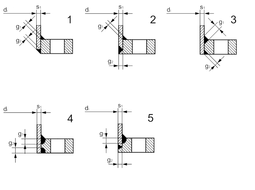
Design of weld
Figure 1 · Figure 2 · Figure 3 · Figure 4 · Figure 5
Welding-neck flange
With welding-neck flange · Without welding-neck flange
Frequently asked questions
How does the AD 2000 flange calculation differ from EN 1591-1?
AD 2000 B7/B8 is a strength method with fixed minimum loads and separate verifications per condition — robust, fast and well established for classical vessel design. EN 1591-1 is a leak-tightness and deformation analysis with stiffness interaction of all components and iterative load tracking across the load cases. For standard equipment, B8 is sufficient; where demonstrated leakage rates or large temperature transients are required, EN 1591-1 is the more accurate method.
When do I choose a loose flange instead of a welding-neck flange?
Loose flanges on a hub or lapped end are economical when the wetted part is to be made of a high-grade material (e.g. stainless steel) and the flange itself of unalloyed steel, or when the flange must remain rotatable for alignment. Mechanically, only the ring cross-section carries load in a loose flange, without a contributing hub — for the same loads it therefore builds thicker than a welding-neck flange.
Why can the bolting-up condition determine the flange thickness?
In the bolting-up condition, the full bolt load acts through the largest lever arm (bolt circle to gasket) on the unpressurized flange, while in operation part of the force acts on the pressure side with smaller lever arms. Especially with gaskets requiring a high seating load, the bolting-up condition therefore frequently produces the largest moment and thus the required flange ring thickness.
What must be considered with segmented loose flanges?
Segmented loose flanges ease assembly but interrupt the load-bearing ring. With a split joint in a single ring, the section modulus is reduced considerably; double rings with offset splits behave more favorably because the joints do not coincide. Merkblatt B8 provides dedicated approaches for these cases, which the module applies depending on the type.