Engineering task and calculation objective
The RUER module verifies openings and nozzles on pressure vessels to AD 2000-Merkblatt B9 of the German AD 2000 pressure vessel code. Every nozzle – whether manway, pipe connection or instrument nozzle – weakens the pressure-bearing wall of cylindrical shells, spheres, hemispherical, Klöpper-type (torispherical) or Korbbogen-type (semi-ellipsoidal) heads. The verification to B9 shows whether the remaining load-carrying cross-sections of shell, nozzle neck and, where applicable, reinforcing pad are sufficient to carry the pressure-loaded area.
The method is based on the area compensation approach: the force from the design pressure acting on the pressure-loaded area is compared with the load-carrying cross-sectional areas within the effective load-bearing lengths, each weighted with the allowable stress of the respective material. Shell, nozzle and reinforcement may have different materials with their own nominal design strengths, safety factors and allowances – the smallest K/S value limits the reinforcing contribution that may be credited.
RUER covers set-on and set-through nozzles, block flanges, and multiple openings with adjacent nozzles in the longitudinal and circumferential directions. In practice, the opening verification to AD 2000 B9 is a standard part of every vessel calculation to the AD 2000 code and is carried out for every nozzle of the apparatus.
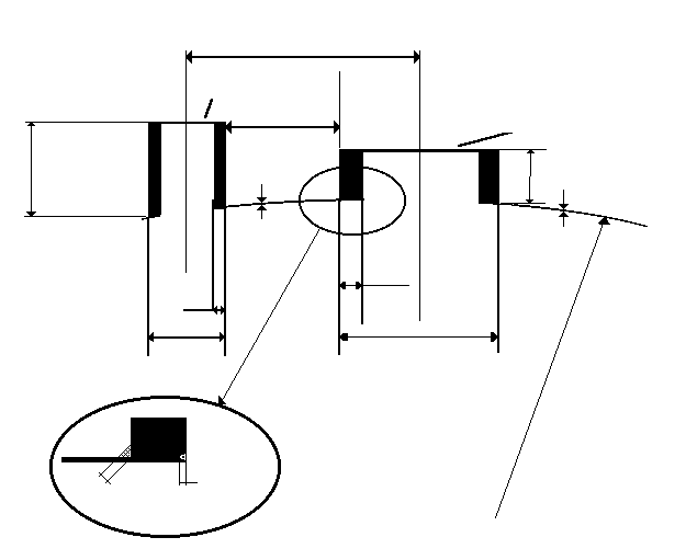
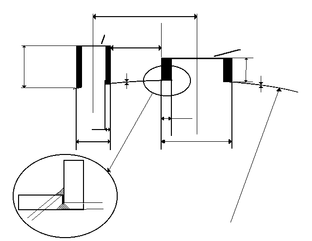
Standard and calculation basis: AD 2000 B9: 2000-10
Calculation workflow
- Select the main body and configuration: First, the configuration is defined (cylinder, sphere, dished end; set-on or set-through nozzle, block flange), together with the design pressure and the design temperature.
- Apply materials separately: For the shell, the nozzle and, where present, the reinforcing pad, separate materials, nominal design strengths, safety factors and allowances for wall thickness undertolerance and corrosion are entered. If an attached part has a lower K/S value than the shell, its load-carrying contribution is only credited proportionally.
- Determine the effective load-bearing lengths: From the diameter and wall thickness of shell and nozzle, the effective load-bearing lengths are determined within which wall cross-sections act as reinforcement; from these follow the load-carrying areas of the shell, the nozzle and the pad.
- Carry out the area comparison: The pressure-loaded area is loaded with the design pressure, the load-carrying cross-sectional areas with the allowable stresses reduced by half the pressure. The strength condition to B9 compares force and load-carrying capacity; among the outputs are the minimum K-value and the utilization.
- Check adjacent openings: For multiple openings, the ligament between adjacent nozzles is additionally verified in the longitudinal and circumferential directions; for cylindrical shells, the direction of the ligament must be distinguished because the circumferential stress is twice as high. The most unfavourable combination governs.
Input quantities
| Quantity | Symbol | Unit |
|---|---|---|
| Final wall thickness of vessel (between nozzles) | se | mm |
| Inside crown diameter | Di | mm |
| Design pressure | p | bar |
| Nominal design strength | K | N/mm² |
| Safety factor | S | – |
| Type (press F7 after change) | ) | – |
| Wall thickness allowance | c1 | mm |
| Corrosion / wear allowance | c2 | mm |
| Final wall thickness of vessel | sa | mm |
| Final wall thickness of nozzle 1 | s1 | mm |
| Final wall thickness of nozzle 2 | s2 | mm |
| Ratio | s1/sa | – |
| Ratio | sa/se | – |
| Outside nozzle diameter 1 | Da1 | mm |
| Outside nozzle diameter 2 | Da2 | mm |
| Weld dimension | g1 | mm |
| Weld dimension | g2 | mm |
| Weld dimension | g3 | mm |
| Weld dimension | g4 | mm |
| Distance between the nozzle middles | t | mm |
| Material | WNr | – |
| Design temperature | T | °C |
| Material | WNr | – |
| Material | WNr | – |
Calculated results
| Quantity | Symbol | Unit |
|---|---|---|
| Height | h1 | mm |
| Area | F1 | mm² |
| Area | F2a | mm² |
| Area | F2b | mm² |
| Area (Minimum of F2a and F2b) | F2 | mm² |
| Area | F | mm² |
| Load | Pu | N |
| Load | Pt | N |
| K/S | Max(Pu;Pt) / F ≤ Kmin / S ≤ | N/mm² |
| Max(Pu;Pt)/F | Max(Pu;Pt) / F ≤ Kmin / S ≤ | N/mm² |
| Minimum K-value | kmin | N/mm² |
Frequently asked questions
Set-on or set-through nozzle – what is the difference in the verification?
With a set-through nozzle, the nozzle neck protrudes into the vessel, and the internal protrusion may also be credited as load-carrying area within its effective length. With a set-on nozzle, only the external part is available. The configuration therefore directly affects the creditable areas in the area comparison and must match the actual construction.
When may a reinforcing pad be credited, and what limits apply?
Reinforcing pads are only effective if they lie flush against the shell and within the effective load-bearing length of the shell. Their creditable thickness and width are limited according to B9; in addition, their load-carrying contribution is reduced via the ratio of allowable stresses if the pad material is weaker than the shell. At elevated temperatures and under fluctuating loads, pads must be assessed critically, since gaps between pad and wall promote thermal stresses and crevice corrosion.
Why does the location of an opening in a dished end matter?
Openings should be located in the spherical crown region, where the membrane stresses are lower and rotationally symmetric. In the knuckle region of Klöpper and Korbbogen heads, high bending stresses prevail; openings there are only permitted to a limited extent under B9 and require special consideration. The distance of the nozzle edge from the knuckle also enters the assessment.
What does the reported minimum K-value mean?
The module rewrites the strength condition in terms of the required design strength: the minimum K-value states the design strength the material would at least have to possess for the verification to be just satisfied. If the actual value is above it, there is a margin; the ratio corresponds to the utilization of the opening region.