Engineering task and calculation objective
This module calculates steam and flash-steam condensation in heat exchanger groups connected in series: superheated or saturated steam is cooled in stages, condenses, and is taken down into the subcooled liquid region, while air is heated on the other side. Up to four stages are balanced – a high-pressure steam stage, a low-pressure steam stage, a flash steam stage, and a condensate stage – so that flash steam from condensate letdown can also be used energetically.
In practice, this kind of calculation is needed when designing steam-heated air heaters, for example in drying plants, HVAC and process air systems, or for the heat recovery of condensate and flash steam streams in a plant's steam network. Engineers who want to calculate steam condensation with flash steam recovery must couple the enthalpy paths from superheated steam through saturation down to subcooled condensate consistently with the air side – exactly what this module does, based on the VDI Heat Atlas (VDI-Wärmeatlas) and the Heat Exchanger Design Handbook.
The inputs are the mass flow of air, its inlet and outlet temperature, the air pressure, and the selected type of the exchanger group; the specific heat capacity of the air is evaluated at the inlet and outlet states and used as the governing mean value in the balance.
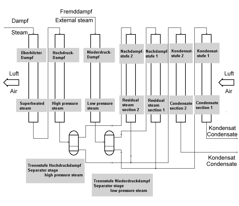
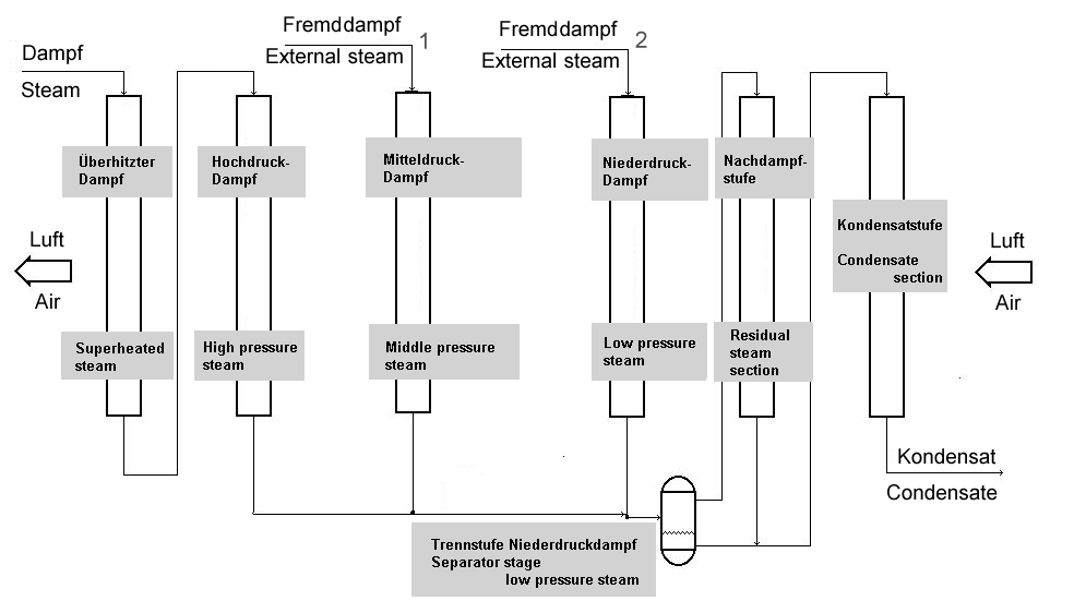
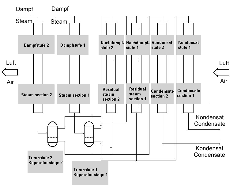
Standard and calculation basis: VDI - Wärmeatlas, Heat Exchanger Design Handbook, Hemisphere Publishing Corporation, New York
Calculation workflow
- Define the type and stage configuration: First, the selected type of the heat exchanger group is defined: which stages (high-pressure steam, low-pressure steam, flash steam, and condensate stage) are present and in which order the air flows through them.
- Balance the air side: From the mass flow of air, the air temperature at inlet and outlet, and the air pressure, the heat duty to be absorbed is determined. The specific heat capacity of the air is evaluated at the inlet and outlet temperatures; the cp value used for the calculation averages both states.
- Track the change of state on the steam side: On the steam side, the change of state is tracked section by section using water/steam property data: desuperheating of the superheated steam down to saturation, condensation at nearly constant saturation temperature, and subsequent subcooling of the condensate. Flash steam produced during condensate letdown is accounted for in the flash steam stage.
- Couple the stages: The energy balances of the individual stages are coupled: the air outlet temperature of one stage is the inlet temperature of the next, and the steam-side mass and enthalpy flows (live steam, flash steam, condensate) must be consistent across all stages.
- Evaluate the results: The results comprise the heat duties of the individual stages, the intermediate air temperatures, and the steam and condensate states at the stage boundaries. This makes it possible to assess the contribution of the flash steam and condensate stages to the total duty and how the group should be designed.
Input quantities
| Quantity | Symbol | Unit |
|---|---|---|
| Amount of condensate | mK | kg/h |
| Steam temperature at inlet | TD ein | °C |
| Enthalpy of superheated steam | hUeD | J/kg |
| Steam temperature high pressure section | TD H | °C |
| Enthalpy of saturated steam at pH | h″H | J/kg |
| Pressure of high pressure section | pH | Pa |
| Enthalpy of saturated steam at pN | h″N | J/kg |
| Steam temperature steam section | TD | °C |
| Enthalpy of saturated steam at pnach | h″n | J/kg |
| Pressure of steam section | pN | Pa |
| Enthalpy of subcooled liquid at TKond and pnach | h | J/kg |
| Steam temperature residual steam section | Tnach | °C |
| Pressure of residual steam section | pnach | Pa |
| Condensate outlet temperature | TKond | °C |
| Selected Type | Bauform | – |
| → Amount of condensate of section 2 | mK 2 | kg/h |
| → Amount of steam of section 2 | mD 2 | kg/h |
| → Amount of condensate of steam section | mK D | kg/h |
| → Amount of steam of steam section | mD D | kg/h |
| Mass flow air | mL | kg/h |
| Air temperature inlet | TL ein | °C |
| → cp of air used for calculation | cpL | J/(kg·K) |
| Air pressure | pL | Pa |
| Low pressure section | TL N a | °C |
Frequently asked questions
What is flash steam and why is it worth recovering?
When hot condensate is let down from a higher to a lower pressure, its enthalpy exceeds the saturated liquid enthalpy at the new pressure – part of it flashes instantaneously into steam (flash steam). Depending on the pressure difference, this typically amounts to a few percent up to more than ten percent of the condensate mass flow. Since this steam carries the full enthalpy of vaporization, it contains a considerable amount of energy that would otherwise be lost through the condensate system or vent losses.
Why is the condensation calculated in separate stages rather than with a single mean temperature difference?
The temperature profile on the steam side is strongly nonlinear: in the desuperheating zone the temperature falls, during condensation it remains nearly constant at saturation level, and in the subcooling zone it falls again. A single log mean temperature difference over the entire apparatus would therefore be physically wrong. Balancing stage by stage (zone by zone) assigns each zone its own driving temperature difference and heat duty.
What role does the air pressure play in the calculation?
The air pressure influences the density and – weakly – the specific heat capacity of the air, and thus enters the energy balance of the air side. For plants at high altitude or in pressurized process air systems, the air mass flow at the same volume flow deviates significantly from the standard state; the balance must therefore be carried out with the actual mass flow and pressure.
Can a stage also drop out completely in operation?
Yes. If, for example, the amount of flash steam decreases because less condensate is let down, the flash steam stage delivers correspondingly less duty and the subsequent stages must take over more – or the air outlet temperature drops. In the design, part-load and outage scenarios of the individual stages should therefore be considered in addition to the rated case, in order to secure the required air outlet temperature.