Engineering task and calculation objective
The IGEL module performs the complete strength verification for pressure-loaded components with simple or complex nozzle geometry – for example an agitator vessel head with numerous connection nozzles, or a shell course with closely spaced openings. It is based on the AD 2000-Merkblätter B1 (cylindrical shells), B3 (dished ends and spheres) and B9 (openings) of the German AD 2000 pressure vessel code, plus the superposition of nozzle forces and moments in line with AD 2000 S3/0 (NozzleSpecApp).
In practice you need this verification whenever calculating multiple openings means more than looking at each nozzle in isolation: when openings in spherical ends, cylindrical shells, Klöpper-type (torispherical) or Korbbogen-type (semi-ellipsoidal) heads lie close together, their weakened zones interact, and the maximum utilization of the main body only emerges from the overall geometry. IGEL checks every nozzle pair and reports the governing combination.
Starting from the design pressure, test pressure, design temperature, material properties with separate safety factors for the operating and test conditions, and the allowances for wall thickness undertolerance and corrosion, the module determines the required wall thickness of the main body and assesses the actual wall thickness for any number of nozzles. It is used as a supplement to the AD 2000 code whenever nozzle loads and opening reinforcement have to be verified together.
Standard and calculation basis: AD 2000 B1 & B3 & B9 &S3.0 (NozzleSpecApp / AD S3/0)
Calculation scope
- Superposition of nozzle loads (NozzleSpecApp / AD S3/0)
- Spherical shells, maximum utilization with multiple nozzles
- Cylindrical shells, maximum utilization with multiple nozzles
- Kloepper type heads, maximum utilization with multiple nozzles
- Korbbogen type heads, maximum utilization with multiple nozzles
Calculation workflow
- Define the main body and load data: The outside diameter and shape of the main body (cylindrical shell, sphere, Klöpper or Korbbogen head) are specified together with the design pressure, test pressure and design temperature.
- Apply material and safety values: For the material, the nominal design strengths for operation and for the pressure test are determined, together with the associated safety factors; the joint efficiency, the wall thickness undertolerance allowance and the corrosion/wear allowance complete the basis of the verification.
- Verify the wall thickness of the main body: In accordance with AD 2000 B1 or B3, the required wall thickness of the main body is calculated for the undisturbed region and compared with the actual wall thickness.
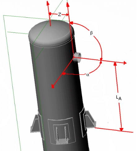
- Enter the nozzle geometry: All nozzles are entered with their position, diameter, wall thickness and type. The number of nozzles determines which neighbouring relationships between openings have to be checked.
- Assess single and multiple openings to B9: For each opening and each pair of adjacent nozzles, the reinforcement verification to AD 2000 B9 is carried out (effective load-bearing lengths, area comparison of the pressure-loaded and load-carrying cross-sections). The most unfavourable ligament width between two openings governs.
- Superpose nozzle loads and report the utilization: External forces and moments on the nozzles are superposed with the pressure loading in line with AD 2000 S3/0. The result is the maximum utilization of the component for the operating and test conditions, together with an evaluation of all strength conditions.
Input quantities
| Quantity | Symbol | Unit |
|---|---|---|
| Design temperature | T | °C |
| Design pressure | p | bar |
| Test pressure | p' | bar |
| Outside diameter | Da | mm |
| Material | Grundkörper | – |
| Nominal design strength (Operation) | K | N/mm² |
| Nominal design strength (Test) | K' | N/mm² |
| Safety factor (Operation) | S | – |
| Safety factor (Test) | S' | – |
| Wall thickness manufacturing tolerance | c1 | – |
| Corrosion / wear allowance | c2 | – |
| Required wall thickness of shell | s = max(sB; sP) | mm |
| Number of nozzles | Ns | – |
| OD Outside diameter | = | – |
| ea Wall thickness | = | – |
| Safety factor | S = | – |
| Wall thickness manufacturing tolerance | c1 = | – |
| Corrosion / wear allowance | c2 = | – |
| Type (A)set-on / (E)set-in / (D)set through / (H)extruded / (B)reinforcement pad | = | – |
| lbi effective length inside the shell | = | – |
| lb actual effective length outside the shell | = | – |
| wr width of reinforcement | = | – |
| hr height of reinforcement | = | – |
| 1 | 1 | mm |
Calculated results
| Quantity | Symbol | Unit |
|---|---|---|
| Required wall thickness (Operation) | sB | mm |
| Required wall thickness (Test) | sP | mm |
| Required wall thickness of shell | s = max(sB; sP) | mm |
| Effective width | b = √[(Di+s0)·s0] | mm |
| Allowable unreinforced opening | dA1 < | mm |
| No mutual influence for | l > = 2·b | – |
| Max. utilization by nozzle configuration | Spannung | % |
| Critical nozzle(s) | Stutzen | – |
| X | FxT = FyT = FzT = | N |
| Y | FxT = FyT = FzT = | N |
| Z | FA = Q = | N |
| X | MxT = MyT = MzT = | Nm |
| Y | MxT = MyT = MzT = | Nm |
| Wind loads or seismic loads see LV modules EN22, EN1991 (EC1). Beben (EC8) WND(DIN 1055) , KSTA, UBC | Mb = Mz = | Nm |
| Wind loads or seismic loads see LV modules EN22, EN1991 (EC1). Beben (EC8) WND(DIN 1055) , KSTA, UBC | Mb = Mz = | Nm |
| Windlasten | Mzu = Qzu = | Nm |
| Querkraft | Mzu = Qzu = | N |
| Scherkraft | FA = Q = | N |
| Querkraft | ME = QG = | N |
| Einspannmoment | ME = QG = | Nm |
Frequently asked questions
When is the single-nozzle verification to AD 2000 B9 sufficient, and when is the multiple-opening assessment needed?
Two openings may only be treated separately if they are far enough apart that their effective load-bearing regions do not overlap. If the ligament width between the nozzles falls below the limits defined in B9, the openings must be verified together – and that is exactly what IGEL is designed for. On agitator vessel heads with many nozzles, mutual interaction is the rule rather than the exception.
Why is the test pressure checked in addition to the operating condition?
During the hydrostatic pressure test, the pressure is well above the design pressure, but a lower safety factor applies to the yield strength at room temperature. Which condition governs depends on the ratio of the design strengths at design and test temperature; the module therefore performs both verifications with separate strength values and safety factors.
How do external nozzle loads enter the verification?
Forces and moments from connected piping generate additional membrane and bending stresses in the opening region, which superpose with the stresses from internal pressure. IGEL accounts for this superposition in line with AD 2000 S3/0 (NozzleSpecApp), so the reported utilization includes not only the pressure but also the nozzle loads.
Which shapes of main body does the module cover?
Cylindrical shells, spherical shells or spherical ends, and Klöpper (torispherical) and Korbbogen (semi-ellipsoidal) heads – each with the maximum utilization for multiple openings. For dished ends, note additionally that openings should generally be located in the spherical crown region; more stringent requirements apply in the knuckle region.