Engineering task and calculation objective
This module calculates support rings and ring girders on vertical process equipment to DIN 28084-1. A support ring encircles the vessel and transfers its weight load into the structural steelwork at discrete support points — the typical way of supporting equipment in platforms and structures. The module determines the allowable load of the ring and compares it with the actual force from the equipment weight and supplementary loads.
The load capacity is determined from two limiting conditions: the safe load derived from the bending moment in the ring section, and the maximum load derived from the shear force. Via the non-dimensional lever arms of the support force and the line load, the calculation captures the fact that the vessel load is introduced into the ring as a circumferential line load but carried off only at discrete support points — between the supports, bending moments and shear forces arise in the ring cross-section. Among the outputs are the allowable force for the standard case and for a support ring on 8 support points.
The verification is needed in the installation planning of columns, vessels and heat exchangers in buildings and structural steelwork, where skirts or bracket supports cannot be used and the load is to be distributed via a circumferential ring.
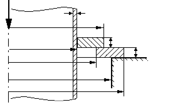
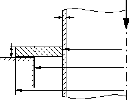
Standard and calculation basis: DIN 28084-1
Calculation workflow
- Define ring geometry and profile: The support ring or ring girder is described by its diameter and profile cross-section; the cross-sectional properties of the profile (section modulus, area) determine the internal forces it can carry.
- Determine support points and load introduction: The number and position of the support points define the static system of the ring. Via the non-dimensional lever arms of the support force and the line load, the eccentricity between the load introduction from the vessel wall and the support reaction in the steelwork is captured.
- Calculate the load capacity from bending and shear: For the governing ring segment between two support points, the safe load from the allowable bending moment and the maximum load from the allowable shear force are calculated. The smaller value limits the allowable force for the support ring.
- Carry out the verification: The actual force from the equipment weight (operating and test filling, internals, insulation) is compared with the allowable force. With more support points — the module reports the case with 8 support points separately — the moments and shear forces in the ring decrease and the allowable force increases.
Input quantities
| Quantity | Symbol | Unit |
|---|---|---|
| Outside diameter of shell or jacket | d | mm |
| Platform opening diameter | d4 | mm |
| Outside diameter of support ring | d5 | mm |
| Inside diameter of additional ring support | d6 | mm |
| Outside diameter of support ring | d7 | mm |
| Support ring thickness | s2 | mm |
| Support ring thickness | s3 | mm |
| Additional ring support thickness | s4 | mm |
| Thickness of shell or jacket | se | mm |
| Correction factor (1 or 2 / segments) | fa | – |
| Operating temperature | T | °C |
| Material number (support ring) | Werkstoffnummer | – |
| Allowable stress | KT | N/mm² |
| Safety factor | ST | – |
| Weld factor | vT | – |
| Material number (additional ring support) | Werkstoffnummer | – |
| Allowable stress | KZ | N/mm² |
| Safety factor | SZ | – |
| Weld factor | vZ | – |
| Allowable force for additional ring support | FZ | N |
| Allowable force for support ring | FT | N |
| Allowable force for additional ring support (8 points) | FZ8 | N |
| Allowable force of support ring on 8 points | FT8 | N |
| Actual force | Fv | N |
Calculated results
| Quantity | Symbol | Unit |
|---|---|---|
| Safe load for bending | Fb | N |
| Maximum shear force | FQ | N |
| Parameter | K1 | – |
| Parameter 0 | Z0 | – |
| Parameter 1 | Z1 | – |
| Non-dimensional lever of support force | β | – |
| Non-dimensional lever of line load | Δ | – |
| Auxiliary variable | HV | – |
Frequently asked questions
When do you choose a support ring instead of bracket supports?
Bracket supports introduce the load into the vessel wall directly at a few points and generate high local shell stresses there. A support ring distributes the load as a circumferential line load over the entire perimeter — advantageous for thin-walled vessels, large weights, or when the support points of the steelwork do not coincide with possible bracket positions. The price is higher fabrication effort and the additional verification of the ring itself.
Why does the load capacity increase with the number of support points?
The governing bending moment in the ring arises in the span between the supports; its magnitude grows with the support spacing. More support points shorten the segments, reduce bending moment and shear force per segment, and thus increase the allowable total force. The prerequisite, however, is that all supports actually carry equally — height tolerances of the steelwork can lead to substantial load redistribution when many support points are used.
What is the difference between a support ring and a ring girder?
The support ring is welded to the vessel and is part of the equipment; it transfers the load to the supports of the platform. The ring girder is the counterpart on the building side: a ring within the steelwork on which the equipment rests. DIN 28084-1 covers both components with their respective verifications; in practice, both verifications must fit together, in particular the positions of the support points.
Which loads belong in the actual force?
Besides the empty weight of the equipment: the operating filling or — usually governing — the water filling during the pressure test, internals, insulation, and platform loads carried through the vessel. Supplementary loads from wind or connected piping generate uneven support force distributions and may need to be accounted for by increased individual support forces.