Engineering task and calculation objective
The ZAPF module determines, to DIN 28085, the maximum allowable loads of trunnions with reinforcing plates on cylindrical vessel walls. Trunnions are used for lifting, turning, and supporting vessels and columns — during transport, during erection on site, or as bearing points in structural steelwork. The standard applies to equipment made of unalloyed, low-alloy, and stainless steels, as commonly used in process engineering.
The critical issue with trunnions is not the trunnion itself but the local load introduction into the comparatively thin vessel wall: the trunnion force generates local membrane and bending stresses in the cylindrical shell, which are limited to an allowable level by the reinforcing plate. For this purpose, DIN 28085 provides matched design configurations and associated load-bearing capacity values, so the verification of the local load introduction can be carried out without an elaborate local stress analysis.
Anyone who wants to calculate the load capacity of a trunnion obtains from the module the allowable forces as a function of vessel diameter, wall thickness, trunnion size, and material — a fast, code-compliant alternative to a case-by-case local load calculation, for example per WRC Bulletin or DIN EN 13445-3 clause 16.
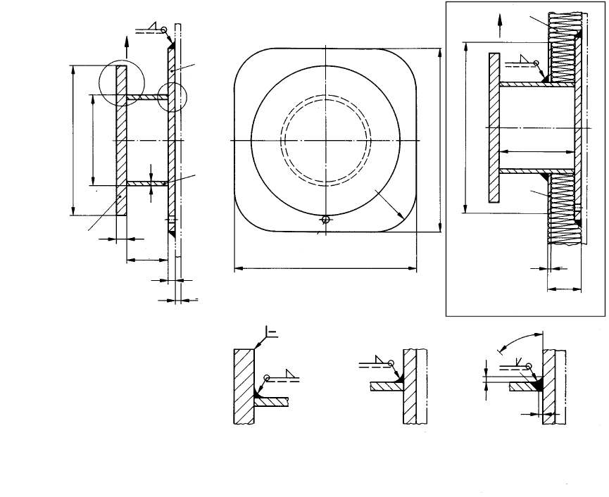
Standard and calculation basis: DIN 28085
Calculation workflow
- Define vessel and trunnion geometry: The starting point is the diameter and the actual wall thickness of the cylindrical shell together with the selected trunnion size and its reinforcing plate according to the design configurations of DIN 28085.
- Assign material and temperature: For the shell and trunnion material (unalloyed, low-alloy, or stainless steel), the strength values at design temperature are used; they determine the allowable local loading of the wall.
- Define load direction and load case: Depending on the application, the trunnion force acts radially, tangentially, or axially with respect to the shell — for example when lifting a horizontal vessel or uprighting a column. Separate load capacity limits apply for each direction.
- Determine the maximum load capacity: The module determines the maximum allowable load of the trunnion from the characteristic values of the standard and compares it with the actual load from the vessel weight including internals, contents, and dynamic allowances.
- Document the verification: Finally, it is checked that the actual load is below the allowable load capacity; otherwise a larger trunnion size, a thicker reinforcing plate, or a modified load arrangement must be chosen.
Input quantities
| Quantity | Symbol | Unit |
|---|---|---|
| Design strength | K | N/mm² |
| Safety factor for weld | S | – |
| Dynamic factor | γ | – |
| Allowance | c1 | mm |
| Allowance | c2 | mm |
| Outside diameter of vessel | DA | mm |
| Diameter of trunnion | d1 | mm |
| Length of trunnion | l1 | mm |
| Final wall thickness of vessel | se | mm |
| Thickness of trunnion | s1 | mm |
| Thickness of cover plate | s2 | mm |
| Width of reinforcement plate | b | mm |
| Total weight | FM | N |
| Actual force on one trunnion | ≥ | N |
| Slenderness factor | X | – |
| Slenderness factor | Pa | – |
| Force factor (from fig. 5) | fl | – |
| Force factor (from fig. 6) | fu | – |
| Allowable longitudinal load | ≥ | N |
| Allowable circumferential load | ≥ | N |
| Distance from center of mass to column base | lM | mm |
| Distance from trunnion to column base | lZ | mm |
| Actual force on one trunnion when erecting a lying vessel | ≥ | N |
| Design temperature | T | °C |
Calculated results
| Quantity | Symbol | Unit |
|---|---|---|
| Actual force on one trunnion | ≥ | N |
| Auxiliary value | A | mm² |
| Auxiliary value | w | mm³ |
| Allowable longitudinal force | FL | N |
| Required thickness of reinforcement plate | s3e | mm |
Calculation options
Consider lifting of standing vessel?
Yes · No
Consider lifting of lying vessel?
Yes · No
Consider load during erection?
Yes · No
Frequently asked questions
Which vessels does DIN 28085 apply to?
The standard applies to trunnions with reinforcing plates on cylindrical walls of equipment used primarily for process engineering purposes and made of unalloyed, low-alloy, or stainless steels. For other materials, unreinforced trunnions, or significantly deviating geometries, an individual verification of the local load introduction is required.
Why is the reinforcing plate so important?
The trunnion force is introduced into the shell over a small area and generates high local bending stresses there. The reinforcing plate enlarges the effective load-introduction area and distributes the load, significantly reducing the stress peaks in the vessel wall. The load capacity values of the standard apply only to the standardized combination of trunnion and reinforcing plate.
Must dynamic loads be considered during lifting?
Yes. During lifting, turning, and setting down, impact and oblique-pull forces occur that can be well above the static weight force. It is common practice to apply impact factors to the lifted weight and to account for the sling angle; the resulting increased force must remain below the allowable load capacity of the trunnion.
What is the difference between trunnions and lifting lugs?
Trunnions are cylindrical welded attachments that are engaged with shackles, wire rope slings, or supports; lifting lugs are plate tabs with a hole. Trunnions are particularly suited for turning and uprighting, because the rigging can roll on the trunnion, and they introduce the load into the shell over a larger area.