Engineering task and calculation objective
The S31 module performs the general stability verification for vertical vessels on skirt supports to AD 2000-Merkblatt S3/1 of the German AD 2000 pressure vessel code. Columns, reactors and storage vessels are frequently set down on the foundation via a cylindrical skirt; the skirt must safely transfer the weight of vessel and filling, the resulting moments from wind, earthquake or connected piping, and the normal forces into the base ring and the anchorage.
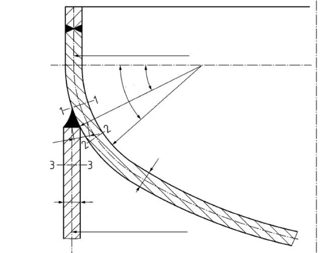
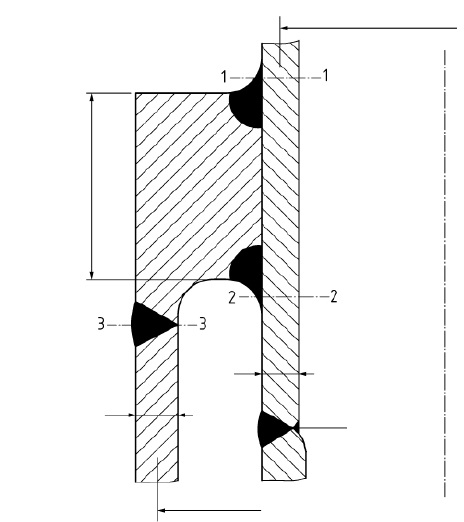
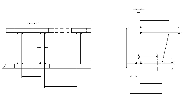
The module covers the connection variants common in practice: the skirt can be attached to the cylinder – slipped over or via a support ring – or start in the knuckle region of Klöpper-type (torispherical) or Korbbogen-type (semi-ellipsoidal) heads. The skirt itself may contain one or two opposite cut-outs (e.g. for pipe penetrations or manways) and may be anchored in the foundation via a single base ring or a double ring with anchor bolts.
The governing sections are verified for the load cases operation, test, erection and special case – each with its own safety factors. Inputs are, besides the design pressure and temperature, the resulting moments and normal forces at the section planes, the weights of filling and vessel components, and the geometry and materials of vessel wall and skirt, including the eccentricity between the vessel and skirt mid-surfaces.
Standard and calculation basis: AD 2000 S3/1: 2018-05
Calculation workflow
- Define load case and section forces: For the selected load case (operation, test, erection or special case), the design pressure, the design temperature, and the resulting moment and resulting normal force at section 1-1 (skirt connection) are entered; added to this are the weights of the filling and of the vessel components, including those below section plane 2-2.
- Enter the geometry of vessel and skirt: The mean vessel diameter and vessel wall thickness without allowances, the mean skirt diameter and skirt wall thickness, and the eccentricity between vessel wall and skirt describe the load path at the connection. The connection type (at the cylinder, via a support ring, or at the knuckle of dished ends) determines the verification model.
- Apply material values per component: For the vessel wall, the skirt and further components, the material, the nominal design strength and the safety factors for operation, test and the respective load case, as well as the allowances for wall thickness undertolerance and corrosion, are established separately.
- Verify the stresses at the governing sections: From normal force, moment and pressure, the longitudinal stresses in the vessel wall and the skirt are determined and compared with the allowable values. On the compression side, the stability (buckling) of the skirt must additionally be checked; the eccentricity of the connection generates local bending stresses, which are superposed.
- Size cut-outs, base ring and anchorage: Cut-outs in the skirt are accounted for via the remaining load-carrying cross-sections. Finally, the base ring (single or double ring), the foundation bearing pressure and the required anchor bolts are verified for the most unfavourable load case – usually the empty vessel under wind moment.
Input quantities
| Quantity | Symbol | Unit |
|---|---|---|
| Load case Operation=1; Test=2; Installation=3; Special case=4 | Lastfall | – |
| Comment | Bemerkung | – |
| Design pressure | Pue | bar |
| Design temperature | T | °C |
| Resulting moment in section 1-1 | M1 | N·mm |
| Resulting normal force in section 1-1 | F1 | N |
| Weight of filling | FF | N |
| Weight of vessel components | FG | N |
| Weight of vessel components below Section 2-2 | ΔFG | N |
| Hydrostatic pressure in the connection area | PH | bar |
| Resulting moment in section 4-4 | M4 | N·mm |
| Additional normal force | Fadd | N |
| Maximum moment in Section 5-5 | M5 | N·mm |
| Resulting normal force in Section 5-5 | F5 | N |
| Vessel wall thickness | seB | mm |
| Outside vessel diameter | DaB | mm |
| Skirt wall thickness | seZ | mm |
| Outside skirt diameter | DaZ | mm |
| Height of support ring | h | mm |
| Inside knuckle radius | r | mm |
| Opening diameter | d | mm |
| Bolt circle diameter | Dt | mm |
| Number of anchor bolts | n | – |
| Final root diameter of the anchor bolts | dk | mm |
Frequently asked questions
Which load case usually governs the anchorage?
For the anchor bolts, the empty, erected vessel under maximum moment (wind, earthquake) is usually critical, because the stabilizing weight is then smallest and the largest uplift force arises on the tension side. For the compressive stresses and the buckling check of the skirt, on the other hand, the filled vessel (operation or water fill during the hydrostatic pressure test) is often governing. That is why all load cases must be calculated separately.
Why is the skirt connection at the knuckle of dished ends regulated separately?
If the skirt starts in the knuckle region of a Klöpper or Korbbogen head, the skirt forces enter a region that is already subject to high bending stresses from internal pressure. In addition, the head wall is curved there, so the introduced longitudinal forces generate deviation forces. The Merkblatt provides dedicated verifications for this that capture the superposition of these effects.
How do cut-outs in the skirt affect the verification?
Cut-outs reduce the load-carrying cross-section and the section modulus of the skirt and generate stress concentrations at the cut-out edges. S3/1 permits one or two opposite cut-outs and regulates how they are accounted for in the stress and stability verifications; large cut-outs may require edge reinforcements. The position of the cut-outs relative to the moment direction should be assumed in the most unfavourable sense.
What is meant by the eccentricity between vessel wall and skirt?
With a slipped-over skirt or differing wall thicknesses, the mid-surfaces of vessel wall and skirt do not line up. The longitudinal force jumps by this offset at the connection and generates a local bending moment proportional to force times eccentricity. This additional moment is superposed in the connection verification and can govern the design for thin-walled vessels.