Engineering task and calculation objective
The S33 module performs the general stability verification for vessels with dished heads on leg supports to AD 2000-Merkblatt S3/3 of the German AD 2000 pressure vessel code. Smaller and medium-sized vertical vessels – batching vessels, agitated vessels, receivers – are frequently placed not on a support skirt but on three or four support legs welded directly to the lower dished head. The legs introduce weight loads and moments locally into the spherical crown of the head, whose wall thickness was primarily sized for internal pressure.
Two things therefore have to be verified: the local loading of the head wall at the load introduction point – superposed with the stresses from the design pressure – and the load-carrying capacity of the legs themselves. The support legs can be attached to the head with or without a reinforcing plate; a reinforcing plate distributes the leg force over a larger area of the crown and reduces the local bending stresses. Anchorage in the foundation is provided via square or circular base plates.
The method to AD 2000 S3/3 thus supplements the pressure design of dished heads to AD 2000 B3 with the additional forces from the installation – a verification that regularly governs the design for medium-filled vessels with agitator moments or attachment loads.
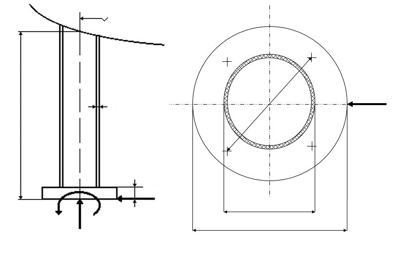
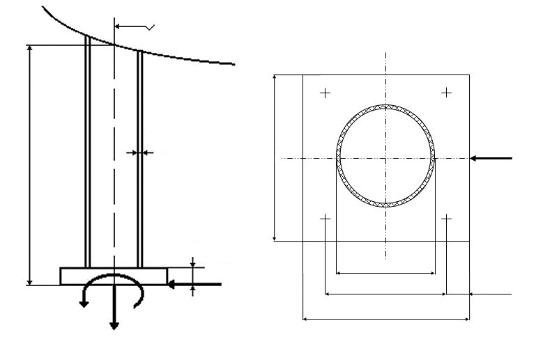
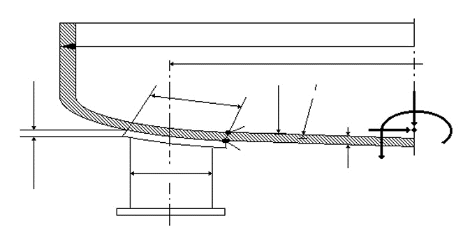
Standard and calculation basis: AD 2000 S3/3: 2001-09
Calculation workflow
- Compile loads and load cases: Weight loads of vessel, internals and filling, together with moments and horizontal forces (e.g. from an agitator, piping connections or start-up impulses), are recorded for operation, testing and erection and distributed to the individual legs; the uneven load distribution under moment action is taken into account.
- Enter the geometry of head and legs: The head type (Klöpper or Korbbogen head), the wall thickness, the leg position on the crown, the leg cross-section and height, and any existing reinforcing plate describe the load introduction. The leg position should lie in the crown region, not in the knuckle.
- Verify the local head loading: At the introduction point, the local membrane and bending stresses from the leg force are determined and superposed with the stresses from the design pressure. With a reinforcing plate, the effective introduction area increases accordingly.
- Size legs and base plates: The support legs are verified against compression and buckling; the square or circular base plates against foundation bearing pressure and bending. For uplift forces from moments, the anchorage in the foundation is checked.
- Assess all load cases: For each load case, the strength conditions are evaluated with the associated safety factors; the most unfavourable combination of leg force, moment and simultaneously acting pressure governs.
Input quantities
| Quantity | Symbol | Unit |
|---|---|---|
| Load case Operation=1; Test=2; Installation=3; Special case=4 | Lastfall | – |
| Comment | Bemerkung | – |
| Design temperature | T | °C |
| Design pressure in connection section | Pges | bar |
| Total moments in the connection section | Mges | N·mm |
| Minimum vertical force | Fvmin | N |
| Maximum vertical force | Fvmax | N |
| Maximum horizontal force | Fh | N |
| Number of leg supports | n | – |
| Springing force of the anchor bolts | Fs | N |
| Number of anchor bolts / plate | ns | – |
| Leg support circle diameter AD 2000 S3/3 does neither cover the calculation of legs attached to the outer knuckle area of dished heads nor the calculation of legs attached to the cylindrical shell. | dF | mm |
| Wall thickness of the head | se | mm |
| Inside radius of the head | R | mm |
| Thickness of the reinforcing plate | sV | mm |
| Diameter of the reinforcing plate | DV | mm |
| Outside diameter of the leg supports | DF | mm |
| Wall thickness of the leg supports | seF | mm |
| Height of the leg supports | hF | mm |
| Root diameter of the anchor bolts | dK | mm |
| Bolt circle diameter of the circular plate | dt | mm |
| Distance between the anchor bolts | b | mm |
| Diameter of the circular plate | DP | mm |
| Length of the base | l | mm |
Calculation options
Option
Vessel head with reinforcing plates · Vessel head without reinforcing plates · Leg support construction with circular base plate · Leg support construction with square base plate (minimum 4 bolts / plate)
Frequently asked questions
Why is the position of the legs on the dished head so important?
In the crown, the doubly curved shell carries local loads much better than in the knuckle, which is already subject to high bending stresses from internal pressure. Legs should therefore be arranged in the crown region; the further out they sit, the shorter the load path into the foundation becomes, but the closer they move to the critical knuckle zone. The verification captures the actual position via the geometry parameters.
When is a reinforcing plate under the leg required?
When the local bending stresses in the head wall from the leg force, superposed with the pressure, exceed the allowable values – typical for thin-walled heads, high filling weights or additional agitator moments. The plate enlarges the introduction area and reduces the stress peaks. It must be connected tightly all around, so that no gap arises in which moisture can collect (corrosion risk).
Does the verification also cover overturning and buckling safety?
The stability verification comprises the load-carrying capacity of the legs including the buckling check, and the anchorage against uplift forces. For the global overturning safety of the vessel under wind or start-up moments, the overturning and stabilizing moments must be compared; with significant horizontal loads, the anchorage of the base plates must take up the tensile forces. Three legs give static determinacy, four legs demand level foundations or shimming.