Engineering task and calculation objective
The S35 module calculates support rings and ring girders for pressure vessels in accordance with AD 2000-Merkblatt S 3/5, part of the German AD 2000 pressure vessel code. Ring supports are used when a vertical vessel is not set down on a support skirt or legs but rests on a circumferential ring carried by columns, brackets, or a supporting steel structure – typical for apparatus installed in structural steel frames, silos, and vessels in process plants. Anyone who wants to calculate a support ring must consider not only the ring cross-section but also the load transfer from the vessel shell and the location of the support points.
For all relevant load cases – dead weight, filling, test condition, and additional external loads – the program determines the internal forces and moments of the ring (bending moments, normal and shear forces) and compares them with the allowable values. Building on this, it performs the global strength verification of the ring cross-section, the local verification at the load introduction points, and the strength verification of the welds between the vessel shell and the ring.
The basis is AD 2000-Merkblatt S 3/5 (edition 2010-02) from the S3 series "Verification of stability", which supplements the pressure design rules of the B series with the verifications for supports and installation.

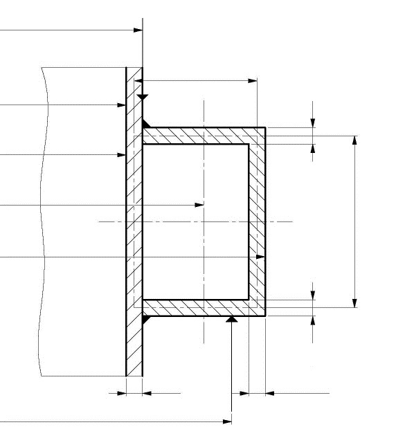
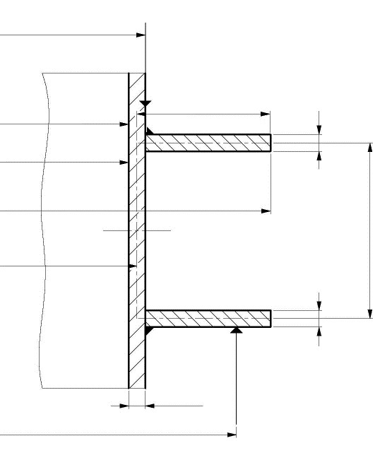
Standard and calculation basis: AD 2000 S 3/5: 2010-02
Calculation workflow
- Define geometry and support arrangement: First, the vessel diameter, wall thickness, ring profile (e.g. rectangular section or reinforced cross-sections with ribs), and the number and arrangement of support points on the ring are defined. The weld design between shell and ring is also part of the input.
- Compile load cases: For the operating and test conditions, the vertical weight loads (vessel, internals, filling, insulation) and additional loads such as moments and point forces from connected components are recorded. The total load yields the line load acting on the ring.
- Determine the internal forces of the ring: Using the relationships given in the Merkblatt, the governing internal forces in the ring are calculated for each load case: bending moments about both axes, normal force, and shear force, each at the critical locations between and above the supports.
- Global and local strength verification: The stresses in the ring cross-section resulting from the internal forces are compared with the allowable stresses of the ring material at the design temperature. In addition, the local loading at the load introduction points (supports, ribs) is verified.
- Weld verification: Finally, the connecting weld between the vessel shell and the support ring is checked: the transmitted shear and normal stresses in the weld must remain below the allowable weld stresses.
Input quantities
| Quantity | Symbol | Unit |
|---|---|---|
| Inside diameter of vessel | d1 | mm |
| Inside ring diameter | d3 | mm |
| Outside ring diameter | d4 | mm |
| Diameter to the transverse force centre | d5 | mm |
| Diameter to the line load | d6 | mm |
| Diameter to the support force | d7 | mm |
| Wall thickness of the ring | e3 | mm |
| Wall thickness of the ring | e4 | mm |
| Wall thickness of the ring | e5 | mm |
| Wall thickness of the stiffening fin | e6 | mm |
| Allowable load of the fin material | fR | N/mm² |
| Allowable stress | f | N/mm² |
| weld 1 | ≥ | N/mm² |
| Allowable standard bending moment | mb | N·mm |
| Allowable standard torsional moment | mt | N·mm |
| Number of supports | ns | – |
| Allowable standard transverse force | qt | N |
| Distance | t0 | mm |
| Fin width | u | mm |
| Fin height | w | mm |
| Geometric ratio | y | – |
| Cross section area of the ring | AT | mm² |
| Fictitious total force (per support) | F | N |
| Torsional moment in the ring cross section | Mt | N·mm |
Calculation options
Equal supports
No · Yes
External ring
No · Yes
Type of profile
Box Profile · Open Profile
Load case
Operation · Testing · Assembly · Exception
Frequently asked questions
When is a ring support the right choice compared with a support skirt or saddles?
Ring supports are a good option when a vertical vessel is suspended in a platform or steel-frame structure and the space below the bottom head must remain clear, for example for outlet devices or agitator drives. Support skirts (AD 2000 S 3/1) transfer the load into the foundation over a full circumference, while saddles (S 3/3) are intended for horizontal vessels. The support ring allows the vessel to rest on just a few columns, but in return concentrates bending moments in the ring, which have to be verified.
Why is the global stress verification of the ring not sufficient on its own?
Between the supports the ring acts as a beam in bending, but at the support points themselves concentrated load introductions occur, producing local stress peaks in both the ring and the vessel shell. AD 2000 S 3/5 therefore requires, in addition to the global verification of the ring cross-section, a local verification at the load introduction points and a verification of the connecting welds – a ring can be adequate globally yet overloaded locally.
Which load cases must be examined as a minimum?
As a rule, the governing cases are the operating condition with filling and additional loads and the test condition with water filling, which for gas vessels or vessels containing a light medium often produces the highest weight load. In addition, external forces and moments from piping, attachments, or wind must be taken into account insofar as they are carried through the support.
Does the internal pressure affect the verification of the support ring?
The ring itself primarily carries the weight and additional loads. At the connection point, however, the membrane stresses of the pressure-bearing shell are superimposed on the local bending stresses from the ring support. The shell must therefore be designed for pressure according to the B series, and the interaction at the connection is captured in the local verification of the Merkblatt.