AD 2000 – Pressure vessel calculations
Understand pressure vessels as a connected engineering task — from shell and head to opening.
Package overview, engineering foundations, detailed module operation, real program images and a freshly executed connected teaching case. Not approval of a real construction.
No chapter found. Try another search term.
Chapter 01What this package handbook covers
A pressure vessel is not described by a single equation. Its shell, heads, openings, flanges, supports and, where relevant, cyclic loads require different assessments. This handbook therefore starts with the shared engineering workflow before explaining individual module roles. You will learn to build a calculation, interpret its results and follow changes across project chapters.
The package map covers all 45 identifiers in the inspected AD 2000 module group. The detailed operating guides in this first edition cover B1, B3 and B9. Other modules receive an engineering role and selection guide, not an equivalent individual handbook yet. A project chapter number is not a module identifier: B1 may, for example, occupy chapter 2.
Work in a copy of the supplied demonstration project. Its numbers teach software operation; they are not an approved vessel design. The example intentionally includes only a small selection of assessments and is not a fabrication document.
A useful reading path
- New users: read the division of tasks, foundations and first steps.
- Load the example and reproduce the B1/B3/B9 pressure change.
- Use the three module guides to associate each result with its component and load case.
- Continue with inverse calculation, variants and the review record.
- Use the package map for additional tasks and check the applicable code basis.
Chapter 02From vessel to appropriate assessment
Start with a sketch of the physical component: which space is subject to which pressure? Where do geometry, material or thickness change? Where are forces introduced? These boundaries determine the chapters you need. A physical connection between components does not automatically create a software variable link.
The B1 / B3 / B9 learning chain
- B1: a cylindrical shell under internal pressure; the module also provides a spherical construction.
- B3: a dished head; shape, pressure type, knuckle, crown and straight flange affect the conditions being assessed.
- B9: an opening in the parent shell; the locally available load-bearing geometry must match the opening configuration.
These three chapters can share one design pressure. They still answer three different questions. An unremarkable B1 shell check does not establish the adequacy of the head or opening. Likewise, a low B9 utilisation must not be interpreted as the pressure margin of the entire vessel.
When does the project grow?
External pressure requires a stability assessment, for example B6 for a cylindrical shell and an appropriate B3 head configuration. Piping forces on a nozzle may require additional local-load assessments. A horizontal vessel on saddles poses a different support problem from a vertical skirt-supported vessel. Cyclic loading is a separate subject; a static pressure check alone does not settle it.
The module group is an organisational aid, not a guarantee that every member is based exclusively on an AD 2000 sheet. It also contains supporting dimensioning, loading and literature-based methods. Record the specific basis of each method in the calculation documentation.
Back to top ↑Chapter 03Package map: all 45 modules
All 45 configured package members are placed here. The group labels in this table are teaching aids, not additional package definitions. “Overview” means source/catalogue review, not an executed example assessment.
| Identifier / display | Topic | Task and use | Depth in this edition |
|---|---|---|---|
| 1991 / EC1 | Loads | Wind actions according to Eurocode 1 Prepare wind actions for the structure; package membership does not turn this into an AD sheet. | Overview; individual handbook pending |
| ADZ1 | Basis | Registered Z1 supporting entry The inspected desktop calculation routine exits immediately. No usable complete assistant is inferred from this registration; review the Web workflow separately. | Overview; individual handbook pending |
| ADZ2 | Basis | Registered Z2 supporting entry The inspected desktop calculation routine exits immediately. Its hazard-analysis catalogue classification does not establish a fully checked Web assistant. | Overview; individual handbook pending |
| AHAB / Podest | Supports | Single central cylindrical support (Podest) Assess a local support using the specified WRC/AD basis. | Overview; individual handbook pending |
| AKR | Pressure parts | External jacket knuckles Assess a formed transition of an external jacket. | Overview; individual handbook pending |
| B0 | Basis | Calculation basis and testing Establish shared assumptions and testing conditions, not replace all component assessments. | Overview; individual handbook pending |
| B1 | Pressure parts | Cylindrical and spherical shells under internal pressure Determine shell thickness and allowable pressures; detailed teaching case in this handbook. | Detailed guide + case |
| B10 | Pressure parts | Thick-walled cylinders Check this method’s applicability for the corresponding thick-wall internal-pressure case. | Overview; individual handbook pending |
| B11 / B1.1 | Pressure parts | Pipe bends (displayed as B1.1) Assess curved pipe geometry rather than a straight cylindrical shell. | Overview; individual handbook pending |
| B13 | Connections | Single-wall bellows expansion joints Address the geometry and loading of a bellows expansion joint. | Overview; individual handbook pending |
| B2 | Pressure parts | Conical shells Assign conical regions and the selected internal/external pressure condition. | Overview; individual handbook pending |
| B3 | Pressure parts | Dished heads Assess knuckle, crown and straight flange for the selected shape and pressure type; detailed here. | Detailed guide + case |
| B4 | Pressure parts | Dished covers Assess cover geometry using its designated method. | Overview; individual handbook pending |
| B5 | Pressure parts | Flat ends and plates Assess flat rather than dished pressure-retaining components. | Overview; individual handbook pending |
| B51 | Heat exchangers | Tubesheets Assess a heat-exchanger tubesheet under its relevant boundary conditions. | Overview; individual handbook pending |
| B51A | Heat exchangers | Axial forces Address the supplementary axial-force task for tubesheet/heat-exchanger assessment. | Overview; individual handbook pending |
| B51C | Heat exchangers | Circular tubesheets with projecting flange Select this specific tubesheet/flange geometry. | Overview; individual handbook pending |
| B51F | Cyclic loading | Fatigue of fixed tubesheets Assess fatigue using the separate RKF basis named by the module. | Overview; individual handbook pending |
| B5A1 | Pressure parts | Rectangular tubes and chambers Assess non-circular sections separately. | Overview; individual handbook pending |
| B6 | Stability | Cylindrical shells under external pressure Assess stability and applicable stiffening geometry instead of internal-pressure thickness alone. | Overview; individual handbook pending |
| B7 | Connections | Bolts Assess bolting and its connection-load assumptions. | Overview; individual handbook pending |
| B8 | Connections | Flanges Assess flange geometry and joint condition under appropriate loading. | Overview; individual handbook pending |
| B9 | Openings | Single and adjacent openings Assess contributing regions and openings; the single-opening case is detailed here. | Detailed guide + case |
| B9N | Openings | Separate older B9 method branch Establish archive/method identity; do not equate it with the current B9 token. | Overview; individual handbook pending |
| FGB | Pressure parts | Shallow dished heads under internal pressure Review the particular geometry and stated literature basis. | Overview; individual handbook pending |
| HLB | Pressure parts | Welded half-pipes Assess the half-pipe/parent-shell task rather than model a complete external jacket. | Overview; individual handbook pending |
| HPR | Piping | Metallic piping Assign the piping task under the stated HP 100 R basis. | Overview; individual handbook pending |
| IGEL | Openings | Multiple openings and nozzle loads Address multiple openings or superposition of nozzle loads using the appropriate construction. | Overview; individual handbook pending |
| NMX / Nzul | Project overview | Load-cycle counts (displayed as Nzul) Review a project-level compilation based on the participating assessments. | Overview; individual handbook pending |
| PMX / Pmax | Project overview | Allowable pressures (displayed as Pmax) Read project-level pressure evaluation; inspect the contributing cases and components. | Overview; individual handbook pending |
| PRAT | Dimensions | Bracket dimensions Select dimensions under the stated DIN basis; dimension selection alone is not stress verification. | Overview; individual handbook pending |
| RUER | Openings | Nozzles on vessels Identify the separate older B9-based nozzle case and its source. | Overview; individual handbook pending |
| S1 | Cyclic loading | Simplified fatigue assessment Check whether the simplified route’s prerequisites apply. | Overview; individual handbook pending |
| S2 | Cyclic loading | Detailed fatigue assessment Build the more detailed cyclic-loading assessment. | Overview; individual handbook pending |
| S30 | Supports | General structural-stability principles Establish shared assumptions for structural stability. | Overview; individual handbook pending |
| S31 | Supports | Skirt-supported vessels Assess a vertical skirt-supported vessel. | Overview; individual handbook pending |
| S32 | Supports | Horizontal vessels on saddles Assess saddle supports and their loading conditions. | Overview; individual handbook pending |
| S33 | Supports | Leg-supported vessels Assess leg support with local and global load assumptions. | Overview; individual handbook pending |
| S34 | Supports | Bracket-supported vessels Assess support brackets rather than merely select their dimensions. | Overview; individual handbook pending |
| S35 | Supports | Ring-supported vessels Match ring-support geometry and loading to the assessment. | Overview; individual handbook pending |
| S36 | Additional loads | Nozzles under additional loads Add local nozzle assessment for further applied loads. | Overview; individual handbook pending |
| SG | Dimensions | Sight-glass covers Address the stated sight-glass/cover geometry under its DIN basis. | Overview; individual handbook pending |
| TST | Piping | Tees Assess branch geometry under the bases named by the module. | Overview; individual handbook pending |
| VFLN | Dimensions | Weld-neck flanges Select geometry under DIN 28034; distinguish this from an independent flange assessment. | Overview; individual handbook pending |
| ZAPF | Dimensions | Trunnions Assign the stated DIN 28085 dimensioning task. | Overview; individual handbook pending |
Chapter 04Code, edition and program version
AD 2000 addresses more than calculation equations; its scope also includes construction, manufacturing, testing and documentation. The official AD 2000 overview describes that scope. A module handbook replaces neither the required code nor engineering review of applicability.
Distinguish three versions: the basis selected for the project, the implementation in the module and the publisher's latest release. For example, the inspected B5 catalogue source names 2024-01, while the official update service lists B5:2026-07 as its successor. This does not establish that the newer edition is implemented in this installation; conversely, an older catalogue line alone does not prove an unchanged calculation core.
This documentation explains operation and selected relationships from the inspected source. It does not reproduce complete code texts. For a real design, establish the actual agreed and implemented basis. Merely assembling AD modules is not automatic overall approval or conformity assessment.
Back to top ↑Chapter 05Establish assumptions before entering numbers
Pressure and temperature belong to a load case
Define the design condition, test condition and any additional conditions separately. The example starts at 1.5 bar design pressure, 2 bar test pressure and 120 °C. Later, only design pressure changes to 3 bar. Test pressure is deliberately not adjusted automatically: this is a propagation test, not a recommendation for an acceptable revised test condition.
The displayed unit is part of an input. A number based on the wrong pressure difference, or a confusion between bar and N/mm², can produce a calculated answer to the wrong problem. Also establish whether pressure at the location being assessed needs to include liquid head. The example does not model that distribution.
A material is more than a name
Material selection, product form, temperature, governing thickness and method basis affect the properties adopted. The example uses existing record 1232, displayed as 1.4571(P). This internal identifier helps reproduce the inspected database; it is not a universally stable material code. In a real project, select through the material dialog and review the displayed properties.
In B9, the parent shell, nozzles and reinforcement components may use different materials. Do not copy one strength value indiscriminately into every field. A textual material description alone does not establish that the correct database record was selected.
Actual versus required wall thickness
Required thickness is the result of a specific assessment condition. Actual or final thickness describes your selected geometry. Deductions for tolerance or corrosion can reduce it to a smaller analysis thickness. Record which manufacturing condition the actual thickness represents, particularly for formed heads.
Chapter 06Getting started and operating safely
- Create a new demonstration project or open the example in the next chapter. Save existing customer work separately first.
- Search by identifier in the module browser, read the package and construction, and then open it. This example uses a B1 cylinder, a B3 Klöpper head and a B9 single opening.
- Review the project-standards notification. A suggested standard does not confirm the basis of every chapter.
- Initially fill the mask from top to bottom: calculation options, conditions, material, geometry and results. This is the intended orientation, although the solver permits other input sequences.
- Leave an edited field with Tab and wait for processing. Then inspect the value, unit, field status and message panel.
No rigidly predefined inputs and outputs
SOL ALPHA solves relationships between variables. A known quantity may be prescribed, calculated or received from another chapter. What can be determined depends on the remaining constraints and the solution paths implemented by the module. This does not mean every equation is solvable in every direction, or that contradictory extra constraints become acceptable.
An expression such as 100 + 200 can help with numeric entry. Always check the resulting value and unit after submission. The same applies to an entry with a unit, for example 1 bar in a suitable pressure field: the accepted state is what matters. The general tutorials provide short demonstrations of these individual actions.
Colours guide; they do not certify
In the illustrated standard masks, prescribed numeric fields are light and calculated fields are highlighted in turquoise. Linked fields have an additional indication. Theme, focus and warning state may affect presentation. When in doubt, use Variable info and the connection display. A coloured field alone does not mean “safe” or “approved”.
Back to top ↑Chapter 07Prepare the worked example
Download the B1/B3/B9 starting project · Download the saved video end state. These files come from the checked tutorial library. The fresh replay on 7 September reopens the starting file, creates the links and changes pressure again.
Use File → Open and the local file picker. Depending on your browser, preserve the suggested .sol download extension. The transport filename also has .txt for static web hosts; its bytes remain an unchanged SOL project. Do not edit it as text.
Check the starting state
The left chapter list must contain B1, B3 and B9. B1 shows a cylinder with 600 mm outside diameter, 8 mm wall thickness, 2000 mm length and a calculated inside diameter of 584 mm. B3 uses a Klöpper head with 600 mm outside diameter and 8 mm final knuckle thickness. B9 uses a cylindrical body, a single plain opening without reinforcement and an opening inside diameter of 80 mm.
All three modules initially use 1.5 bar. Check the material display, not just pressure. B9 also specifies 100 mm available effective shell width; this is not reinforcement-pad width. In B3, the 120 mm value in V4 is the maximum nozzle diameter outside 0.6·Da. Temperature is separate, at V30, and happens to be 120 as well, but in °C.
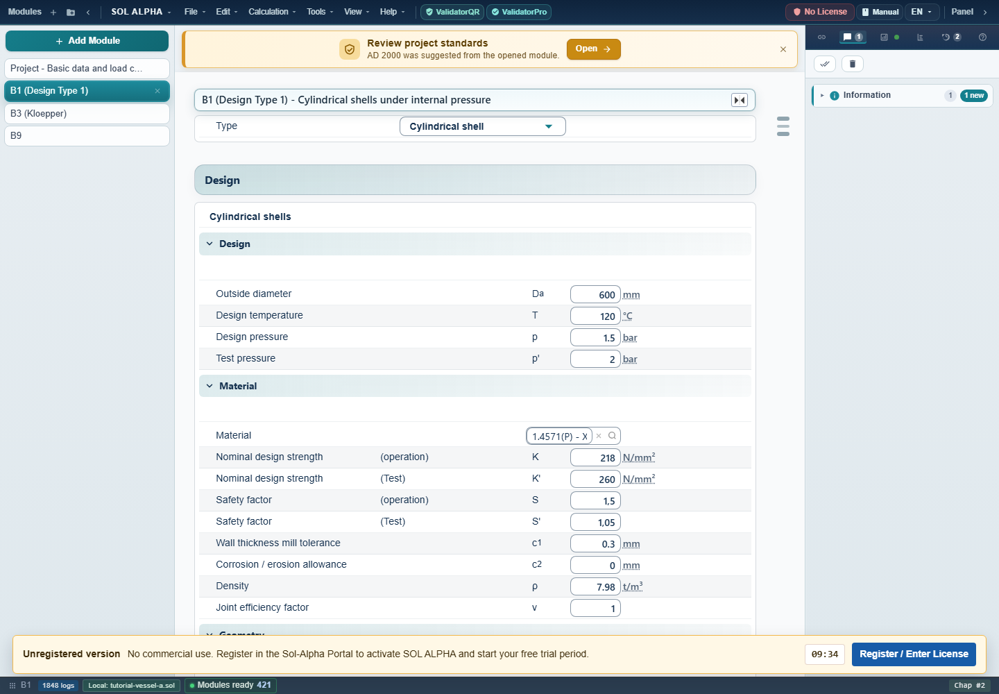
- Three separate chapters in the same project.
- Read design temperature, design pressure and test pressure separately.
- Check the selected material.
Real local replay on 7 September 2026. Original pixels unchanged; HTML highlights. Full-size original.
Chapter 08Link pressure and follow the change
Choose an unambiguous source
- Activate B1 and locate design pressure V3 at 1.5 bar. Do not select test pressure V16.
- Open the field context menu and bookmark the variable.
- Switch to B3. At design pressure V5, choose the connection action from the context menu and select the bookmarked B1 pressure.
- Switch to B9. Link design pressure V2 to the same B1 variable V3.
- Check the connection and received value in both destination chapters. Seeing 1.5 alone does not prove a link exists.
- Return to B1, change design pressure to 3 bar, leave the field and wait for calculation.
- Revisit B3 and B9. Review pressure, result fields, connection state and messages.
This structure has one source and two recipients; it is not a serial transfer of results: B1:V3 → B3:V5 and B1:V3 → B9:V2. Outside diameter, wall thicknesses, materials and test pressure are not linked in this experiment. A later B1 geometry change must therefore not be treated as an automatically completed B3/B9 update.
AutoConnect and repeated modules
Automatic connection aids reduce selection effort but do not replace checking the proposed source. With two vessels each containing a B1, “B1” is insufficient: inspect chapter name, instance and the source field's engineering meaning. Two pressure variables with the same unit can describe different spaces or load cases. The teaching case intentionally uses an explicit bookmark link.
If a destination should subsequently become independently prescribed, first establish the intended engineering separation and remove the link. Overwriting a linked field without considering its origin does not create a reliably documented variant.
Conceptual diagram, not a program screenshot. Only these two pressure links belong to the checked experiment.
Watch the complete operating workflow
English interface, bilingual overlays and subtitles. Video requires Internet access; instructions, images and example files are stored locally. Open video directly.
Back to top ↑Chapter 09Reference results and what they establish
The table contains saved reference values for the tutorial case. The fresh local run on 7 September 2026 confirmed the starting values and the results after the linked pressure change within the recorded tolerances. Distinguish differences in the last displayed digits from rounded mask values.
| Field | Result | 1.5 bar | 3 bar | Unit |
|---|---|---|---|---|
| B1:V1 | Required wall thickness | 0.60947335 | 0.91862756 | mm |
| B1:V18 | Required thickness, operation | 0.60947335 | 0.91862756 | mm |
| B3:V1 | Knuckle thickness | 0.5343772 | 1.0687544 | mm |
| B3:V2 | Crown thickness | 0.31368053 | 0.62719923 | mm |
| B3:V32 | Combined required thickness | 0.5343772 | 1.0687544 | mm |
| B9:V476 | Utilisation opening 1, area I | 6.320895 | 12.648322 | % |
| B9:V462 | Pressure force opening 1, area I | 4774.4854 | 9548.971 | N |
B1 required thickness does not rise exactly in proportion to pressure because the evaluated result incorporates additional assumptions and comparison with the test case. B3 crown and knuckle results must be read separately. In B9, geometry remains unchanged during this pressure edit; pressure force and the utilisation considered here rise approximately proportionally.
What was compared?
The reference was established by editing initially unlinked destination chapters individually. Results from the linked change were then compared with that reference. For these quantities, this tests whether linking reaches the same state as an individual edit. It is not an independent formula check, Desktop/Web parity proof or confirmation of a complete design.
The B3 result image also shows a required knuckle thickness of about 1.67632 mm above the “based on the final wall thickness” section. The table explicitly refers to V1/V2/V32 in that latter section, taking the final thickness into account. Do not confuse different result sections simply because their labels resemble one another.
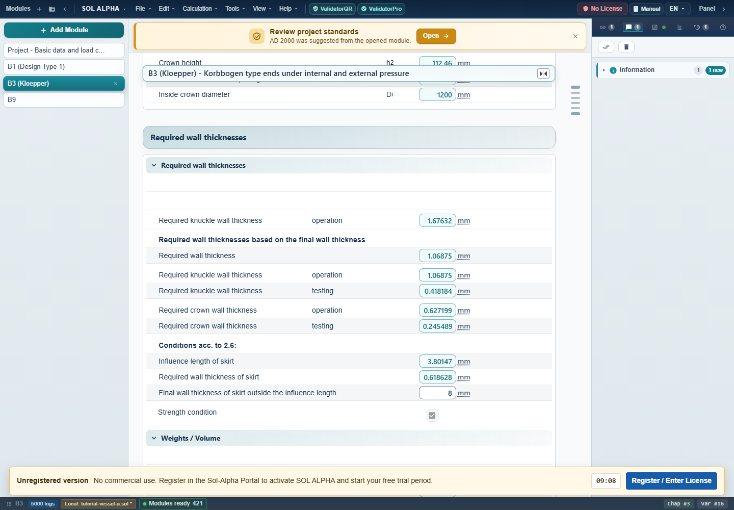
- Preliminary thickness basis: not the reference-table row.
- Reference values belong to the results based on final thickness.
- Also read straight-flange conditions; unknown is not satisfied.
Real local replay on 7 September 2026. Original pixels unchanged; HTML highlights. Full-size original.
Chapter 10B1: shell, thickness and allowable pressure
Which question does B1 answer?
For the cylindrical teaching case, B1 assesses a shell under internal pressure. You can compare required thickness against a chosen geometry or obtain an allowable pressure for an existing wall. Another construction branch treats spherical shells. The selector changes the relationships used; renaming a chapter does not change its construction.
Build it step by step
- Select the cylindrical type. Establish outside diameter and design temperature.
- Prescribe design and test pressure separately. The example uses 600 mm, 120 °C, 1.5 bar and 2 bar.
- Select a material through the dialog. Read the operation/test properties and safety factors.
- Review tolerance c1, corrosion/erosion allowance c2 and joint efficiency v. Adopted values do not validate your manufacturing assumptions.
- Enter an actual intended thickness, 8 mm in the example. The resulting inside diameter must be understandable.
- For volumes and weights, also check component length and the associated density/filling assumptions.
- Read operation and test results separately before assessing the governing result.
Keep four thicknesses distinct
V9 is final wall thickness se. V31 is thickness after the deductions used here: s0 = se − c1 − c2. V18 and V19 are required thicknesses for operation and testing. In the inspected B1 code, V1 takes the larger of those two. “8 mm actual” and “0.918628 mm required” are therefore not competing entries for the same field.
The elementary geometry check is Di = Da − 2·se. With 600 mm and 8 mm, this gives 584 mm. The effective wall portion is 8 − 0.3 − 0 = 7.7 mm. Use these checks as an initial sanity test before investigating more complex results.
Allowable pressure has conditions attached
V36 and V37 give allowable operation and test pressures based on the wall and assumptions in this chapter. The current B1 example shows approximately 37.7872 bar and 64.3818 bar respectively. These are not the allowable operating pressure of the entire project: heads, openings, flanges, other loads and documented applicability limits also need consideration.
Openings, volumes and weights
The B1 opening section provides simplified quantities for unreinforced openings and influence distances. It does not replace arbitrary detailed B9 assessments. In particular, a result capped at the geometric inside diameter is not blanket permission to fabricate an opening of that size.
Distinguish external volume, internal volume and metal volume. Weight quantities may be expressed as forces; the displayed unit governs interpretation. A value in kN must not be passed to a support calculation as kilograms. Likewise, water filling must not silently become the operating contents of a different fluid.
When is B1 insufficient?
For external pressure, different geometry or additional local loads, select the appropriate method. The inspected code includes ratio and thickness conditions, among others, and a limit on joint efficiency. Read the messages: “every field contains a number” does not establish that all conditions are satisfied.
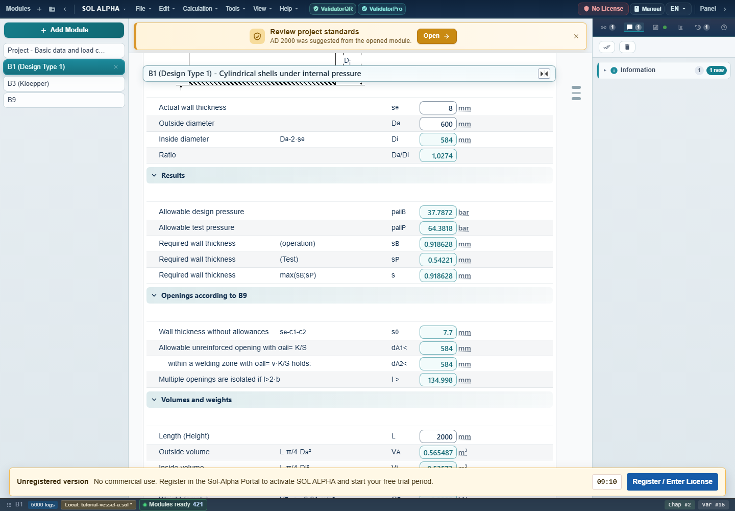
- 8 mm actual thickness gives 584 mm inside diameter here.
- Distinguish operation, testing and combined result.
- Allowable pressures for this shell, not the entire project.
Real local replay on 7 September 2026. Original pixels unchanged; HTML highlights. Full-size original.
Chapter 11B1 inverse calculation: target or persistent constraint?
Suppose your shell geometry is fully determined by Da = 600 mm and se = 8 mm. The solver gives Di = 584 mm. An installation requirement now calls for Di = 580 mm. Outside diameter, inside diameter and thickness cannot all be chosen independently: one previous constraint must be adjusted or released.
Route A: seek a target value
- Locate calculated inside diameter V27 and enter 580.
- When the target/release selection appears, choose the quantity that may actually change. The recorded example selects wall thickness.
- Confirm and inspect: outside diameter stays at 600 mm, thickness becomes approximately 10 mm, and inside diameter becomes 580 mm.
- Then check the field roles. In the evidenced target-seeking workflow, the adjusted thickness remains an input; Di remains calculated.
This distinction matters: target seeking found a suitable input; it did not necessarily exchange the future input/output roles. Di may therefore change again after a later edit.
Route B: prescribe inside diameter persistently
- In a copy of the initial state, release the existing wall-thickness constraint using the release action.
- Then prescribe Di = 580 mm independently while retaining Da = 600 mm.
- Verify that Di is now an input and se is calculated. The geometry again gives approximately 10 mm.
- Review the other assessments and messages after changing thickness. Material properties or allowances may depend on thickness.
The associated B1 inverse-calculation video and saved field-role comparison date from 6 September. The fresh run for this handbook checks the pressure chain, not that entire inverse workflow again. Values around 9.999998 mm in the saved example are numerical approximations to 10 mm, not a meaningful manufacturing tolerance.
Watch the complete operating workflow
English interface, bilingual overlays and subtitles. Video requires Internet access; instructions, images and example files are stored locally. Open video directly.
Back to top ↑Chapter 12B3: head shape, knuckle, crown and straight flange
Choose the construction first
B3 includes Klöpper, Korbbogen and hemispherical heads and different pressure types. Shape and pressure type are separate selectors. The image's general chapter title retains a broader English description; for the illustrated case, the actual “Torispherical head (Kloepper type)” selection governs. Read the selected configuration, not only the heading.
A knuckle joins the crown to the cylindrical edge region. Loading is not uniform across those regions. B3 therefore provides thicknesses and conditions for different parts of the head. One crown result does not automatically settle the knuckle or straight-flange assessment.
Reproduce the teaching case
- Select a Klöpper head under internal pressure. Check the manufacturing option: the example treats knuckle and crown as having equal thickness.
- Check Da = 600 mm, p = 1.5 bar and p′ = 2 bar. V4 = 120 mm belongs to the opening topic, not temperature.
- In the material section, check T = 120 °C and the actual selected material record.
- Check 8 mm final knuckle thickness and the crown thickness resulting from this manufacturing option.
- Read allowances, safety factors and joint efficiency. B3:c1 = 0 mm is part of the demonstration state, not a general recommendation.
- Open results: distinguish the calculation basis, operation/testing and the additional conditions.
Associate results correctly
In the checked case, V1 gives required knuckle thickness and V2 gives required crown thickness in the assessed branch. V32 summarises the thickness requirement there. After changing pressure they are approximately 1.06875 mm, 0.627199 mm and 1.06875 mm. The mask can show another preliminary thickness result above them. The “based on the final wall thickness” heading explains why similarly named fields need not be identical.
Actual straight-flange thickness, required straight-flange thickness and influence length are also separate quantities. The visible strength condition is a result. It is not satisfied by attempting to activate a checkbox. With incomplete inputs, a condition may remain unknown; that is not a confirmed pass.
External pressure and openings
External pressure changes the governing conditions. The inspected source contains quantities for elastic modulus, buckling safety and plastic instability, among others. Do not copy internal-pressure results into an external-pressure case. This first edition does not include a freshly checked complete external-pressure example.
Opening diameters, location zones and, where applicable, neighbouring openings affect specific conditions. The example's maximum nozzle diameter does not establish adequacy for arbitrary position and loading. A real nozzle's location, shape, reinforcement and possible additional loads must match the chosen assessment method.
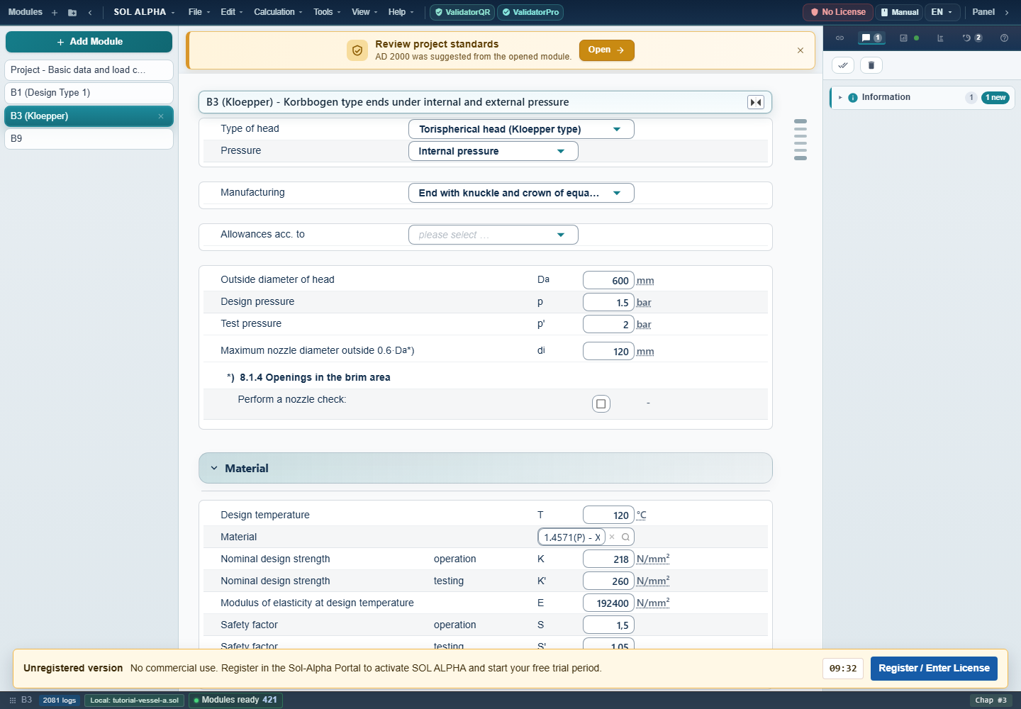
- Head shape and pressure type are separate selections.
- Do not confuse design pressure, test pressure and opening diameter.
- Temperature appears in the material section.
Real local replay on 7 September 2026. Original pixels unchanged; HTML highlights. Full-size original.
Chapter 13B9: openings and contributing regions
Shell and opening type define the scope
The inspected B9 catalogue provides single and adjacent opening configurations. The mask also distinguishes parent-shell shape, load condition, opening type and reinforcement. The teaching case is explicitly a single plain opening without reinforcement in a cylindrical shell. It is not a complete reinforced welded-nozzle example.
The displayed assessment broadly compares pressure loading with the contributing cross-sectional area and associated strength assumptions in the relevant section. It does not count all metal present anywhere around the opening. Geometric limits determine which widths and regions may contribute.
Sequence for the teaching case
- Select a cylindrical body, single opening and operation as the assessed condition.
- For opening 1, verify “Opening” and reinforcement “No”. Do not accidentally enable a nozzle or reinforcement branch.
- Check 120 °C and initially 1.5 bar; pressure will later be received from B1.
- Check parent-shell material and its strength/safety assumptions.
- Check Da = 600 mm, final shell thickness 8 mm, c1 = 0.3 mm and c2 = 0 mm.
- Check opening inside diameter 80 mm and available effective shell width 100 mm.
- Read analysis thickness, diameter definitions, contributing area and utilisation; do not skip messages or geometric conditions.
Three easily confused quantities
Diameter: V61 is the example's final inside diameter, 584 mm. V9 uses an analysis/corroded definition and gives 584.6 mm. Different values are not automatically a transfer error here.
Thickness: V13 is the final shell thickness, 8 mm. V247 is analysis thickness, 7.7 mm. V1 describes analysis thickness at the opening edge and shows 8 mm in this state. Field names and references matter more than expecting the same number everywhere.
Width: V493 limits the available effective shell width. The result image shows an actually contributing width of about 67.533 mm. Entering 100 mm does not force the method to credit all 100 mm. It does not describe a welded reinforcement pad either.
Multiple sections make multiple statements
V476 to V482 refer to different assessment directions, openings and interactions. Which are applicable and visible depends on the configuration. A second opening requires consideration of spacing, direction, geometry and possibly different materials. The single checked section cannot establish the adequacy of adjacent openings.
Materials and additional loads
Where the construction requires them, the source supplies the parent shell, nozzle 1, reinforcement 1, nozzle 2 and reinforcement 2 separately. Only active, physically present components may be interpreted as contributing. This pressure experiment does not assess additional piping forces and moments; a suitable additional-load assessment may be needed.
B9 is not B9N
The inspected catalogue lists B9 with a B9:2023-03 basis and B9N with an older B9 basis. B9N is a separate execution token with different configurations. Do not blindly transfer variable numbers or saved expectations between them. For archive comparisons, always record the actual identifier, construction and source version.
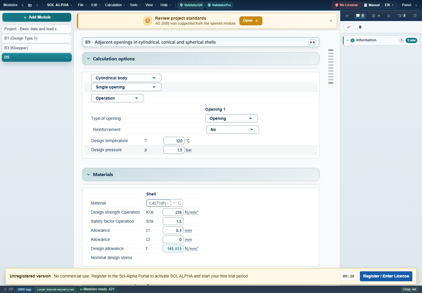
- Cylindrical body, single opening.
- Opening without reinforcement: not a reinforced-nozzle case.
- Pressure and temperature apply to this condition.
Real local replay on 7 September 2026. Original pixels unchanged; HTML highlights. Full-size original.
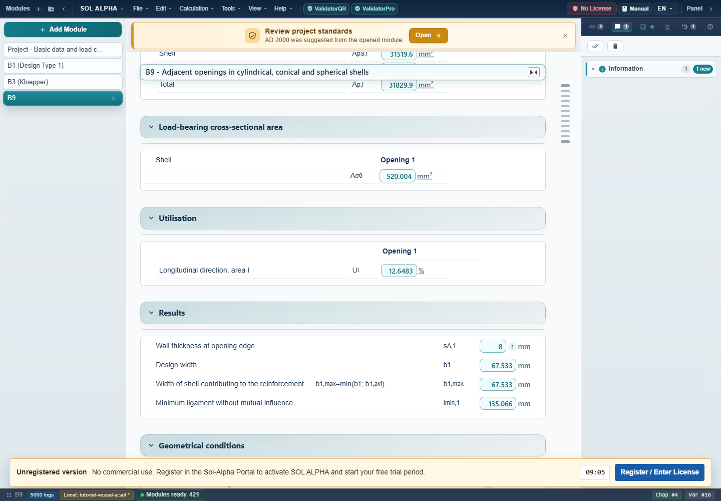
- Utilisation for opening 1, longitudinal direction, area I.
- The credited width here is smaller than the available 100 mm.
Real local replay on 7 September 2026. Original pixels unchanged; HTML highlights. Full-size original.
Chapter 14Build meaningful variants and parameter studies
A variant changes a justified design assumption; it is not merely another column of numbers. First state what must remain fixed, what may change and which results matter. For example, external geometry may be fixed while available thicknesses are explored. In another case, thickness is fixed by available pipe and allowable pressure is the desired output.
A controlled learning exercise
- Save the starting project under a new name.
- Change only the common B1 pressure and verify reception in B3/B9.
- For each state, record pressure, thickness results and relevant utilisation together with warnings.
- Return to 1.5 bar and check whether the same starting results are recovered.
- Only then investigate a second influence. Do not change material, construction, geometry and pressure simultaneously when trying to understand a difference.
The tutorials also demonstrate starting a parameter study through a supported entry sequence such as 1,2...3. Inspect the actual generated study points and units before interpreting results. This handbook does not claim a freshly verified B1/B3/B9 series using that syntax; the checked connection experiment uses two individual pressure states.
A curve point is meaningful only when its assumptions fit the model and the associated assessment is evaluable. Do not interpret hidden, unknown or aborted points as zeros. Save a complete project for interesting variants, not merely a screenshot.
Back to top ↑Chapter 15Save, reopen and investigate differences
A reproducible state needs more than final numbers
Save a short note with the project: identifiers and constructions, program/data version, material selection, changed constraints, connections and outstanding messages. For inverse calculation, record which variable was released. Two projects with identical visible numbers can contain different constraints and react differently to the next edit.
- Save the edited state under a new filename.
- Reopen it in a separate demo environment without replacing unsaved work.
- Check source/destination values and input/calculated roles.
- Check links at the destination variables; matching initial numbers are insufficient.
- Repeat a known edit and verify the reference results.
The supplied end file is the saved state from the existing video. The fresh pressure-chain run reopened the starting file, created links and checked results; it does not establish a new independent save/reopen roundtrip. The evidence keeps these scopes separate.
When a value differs
Start with the first differing input or intermediate quantity, not the final percentage. Check construction, unit, material state, allowances, actual geometry, field role, connection origin and load case in turn. Compare displayed rounding with internally recorded precision. An old archive can itself contain an incompletely resolved state.
A useful defect report includes the smallest reproducible project copy, initial state, exact action, expected/observed result, identifier and variable number. Review confidential data before sharing; the supplied files here are dedicated tutorial cases.
Back to top ↑Chapter 16Review results and hand over the work
Review record for a connected project
- Task: Are component, spaces, loads and design boundaries clearly described?
- Basis: Are actual modules, constructions and implemented method versions recorded?
- Inputs: Are units, materials, temperatures, pressures and manufacturing assumptions correct?
- Geometry: Are shared dimensions consistent? Are different allowances justified?
- Connections: Does each common quantity have an unambiguous source? Are independent load cases kept separate?
- Results: Have operation/testing, required/actual quantities and all relevant sections been reviewed?
- Completeness: Are there unknown conditions, warnings or additional assessments outside the three teaching modules?
- Change check: Do affected chapters reach the expected state after a source edit?
- Handover: Are project file, report, open issues and responsible review stored together?
The software supports the work but cannot infer every unknown condition in your plant. A pressure vessel can remain inadequately assessed despite substantial static thickness margin if a load case is omitted or a method is applied outside its scope.
A report, not a heap of numbers
Organise output by component and load case. Give chapters meaningful names, such as “Shell A”, “Upper head A” and “Opening N1 in shell A”. Explain the common pressure source and document intentional differences. Keep outstanding assessments visible; a clearly stated open issue is more useful than an unsupported green overall verdict.
Back to top ↑Chapter 1720 practical questions
1. Every field is calculated. Am I finished?
You have completed B1 but have not assessed the head, opening or supports. Review result scope, messages and outstanding load cases. A calculated field only establishes its own solution state. → Result review.
Related chapter2. Why does B9 not change with B1?
You edit B1 diameter, but only pressure is linked. Inspect the actual variable connections. Geometry changes are not coupled in the teaching case.
Related chapter3. Two fields show 1.5 bar. Are they linked?
After loading, independent inputs can happen to match. Check the destination connection and follow a small source change in a copy.
Related chapter4. Which pressure should I bookmark?
B1 contains design and test pressure. The documented chain uses V3, not V16. Its destinations are B3:V5 and B9:V2.
Related chapter5. Why is test pressure lower after the edit?
The experiment raises only design pressure to 3 bar; 2 bar test pressure remains independent. Establish and assess the real test condition again. The example does not prescribe a pressure test.
Related chapter6. May I overwrite a calculated number?
You want a 580 mm inside diameter instead of 584 mm. Use target seeking or deliberate release, then verify which field remains prescribed. Do not retain incompatible dimensions.
Related chapter7. Why is Di still calculated after target seeking?
In the evidenced workflow, target seeking adjusted the prescribed thickness. Persistently prescribing Di requires a different role exchange: release thickness, then prescribe Di.
Related chapter8. Why 584 and 584.6 mm in B9?
You are comparing final geometry with an analysis definition. V61 and V9 are different quantities. Check names, deductions and references before assuming an error.
Related chapter9. Is 100 mm the reinforcement width?
In the teaching case, this is V493, available effective shell width. There is no reinforcement pad here. The width actually credited can be smaller.
Related chapter10. Why does B3 show two required knuckle thicknesses?
The result sections use different assumptions. The reference table concerns the evaluation based on final thickness. Read section heading, field identifier and operation/test condition together.
Related chapter11. B3:V4 = 120 — is that temperature?
No. In this example V4 is an opening diameter in mm. Temperature is V30 in °C. Equal numbers are not equal physical quantities.
Related chapter12. Can I read B9 utilisation as overall margin?
After changing pressure you see about 12.65%. Here it belongs to opening 1, longitudinal direction, area I. It does not assess all other sections, components or loads.
Related chapter13. Is B9N just another name for B9?
No. The catalogue lists separate modules with different bases and configurations. Preserve the actual identifier for old projects; do not transfer variable numbers without checking.
Related chapter14. Can I use an internal-pressure calculation for vacuum?
External pressure introduces stability considerations. Select the appropriate pressure type and method; the package includes B6 for cylindrical shells. The internal-pressure video does not validate that other case.
Related chapter15. Why do allowances differ between chapters?
The example uses 0.3 mm in B1/B9 and 0 mm in B3. Manufacturing and allowance settings belong to each chapter. Justify their differences for a real project; do not equalise them automatically.
Related chapter16. Which material should I use to reproduce the case?
The supplied state contains record 1232, displayed as 1.4571(P). For manual entry, check description, product form and properties. The internal number is not a universal material identity.
Related chapter17. A condition remains blank. Does it pass?
With incomplete inputs, a condition may not yet be evaluable. Check missing source quantities and messages. Unknown does not mean satisfied.
Related chapter18. Can I proceed immediately after AutoConnect?
With similar chapters, the wrong engineering source can have the same variable name. First inspect origin, destination and load case; then follow a change.
Related chapter19. Why does my archive differ from the video?
Construction, module version, material data, constraints and links may differ. Align the state first, then locate the first differing quantity. An archived value is not an independent proof of correctness.
Related chapter20. Do I still need a final review?
Yes. Even a stable connected calculation can use incorrect assumptions. The review record supplements operation and recalculation with engineering completeness and documented responsibility.
Related chapterChapter 18Terms and field roles
| Term | Meaning in the workflow |
|---|---|
| Prescribed value | User-established value constraining the solution. |
| Calculated value | Value determined from the currently available relationships; not engineering approval. |
| Linked value | Value originating in another chapter; check source and updating. |
| Release | Remove an input constraint so another quantity can be prescribed or the variable calculated. |
| Target seeking | Find/adjust a suitable changing quantity to reach a desired result; check field roles afterwards. |
| Construction | Active geometric or method configuration of the module. |
| Knuckle / crown / straight flange | Different head regions with their own assessment conditions. |
| Analysis thickness | Thickness used for a particular assessment; may differ from final thickness. |
| Contributing width | Region credited in the chosen assessment, limited by geometry and method. |
| Utilisation | Loading-related result for a particular assessment, not automatically an overall verdict. |
| Load case | Consistent set of loads and boundary conditions. |
| Roundtrip | Save and reopen with verification of values, roles and connections. |
Chapter 19B1 / B3 / B9 field reference
Selected operating and result fields. Numbers are meaningful only together with the identifier. Units and example values, where present, come from the freshly loaded starting case; “—” means not presented here as a numeric example. This does not claim complete documentation of all internal, conditional or hidden fields.
B1
| Variable | Meaning | Starting value | Unit / note |
|---|---|---|---|
| B1:V1 | Required wall thickness | 0.60947335 | mm |
| B1:V2 | Outside diameter | 600 | mm |
| B1:V3 | Design pressure; teaching-chain source | 1.5 | bar |
| B1:V4 | Strength value, operation | 218 | N/mm² |
| B1:V5 | Safety factor, operation | 1.5 | — |
| B1:V6 | Joint efficiency | 1 | — |
| B1:V7 | Tolerance c1 | 0.3 | mm |
| B1:V8 | Allowance c2 | 0 | mm |
| B1:V9 | Final wall thickness | 8 | mm |
| B1:V10 | Length/height | 2000 | mm |
| B1:V16 | Test pressure | 2 | bar |
| B1:V17 | Strength value, testing | 260 | N/mm² |
| B1:V18 | Required thickness, operation | 0.60947335 | mm |
| B1:V19 | Required thickness, testing | 0.54220986 | mm |
| B1:V22 | Material selection | — | Selection/text |
| B1:V24 | Design temperature | 120 | °C |
| B1:V25 | Diameter ratio Da/Di | 1.0273973 | — |
| B1:V27 | Inside diameter | 584 | mm |
| B1:V30 | Density | 7.98 | t/m³ |
| B1:V31 | Wall after deductions | 7.7 | mm |
| B1:V32 | Contributing width | 67.49882 | mm |
| B1:V36 | Allowable operating pressure | 37.787155 | bar |
| B1:V37 | Allowable test pressure | 64.38179 | bar |
| B1:V38 | Construction selector | 1 | - |
B3
| Variable | Meaning | Starting value | Unit / note |
|---|---|---|---|
| B3:V1 | Required knuckle thickness | 0.5343772 | mm |
| B3:V2 | Required crown thickness | 0.31368053 | mm |
| B3:V3 | Outside diameter | 600 | mm |
| B3:V4 | Maximum nozzle diameter outside 0.6·Da | 120 | mm |
| B3:V5 | Design pressure; teaching-chain destination | 1.5 | bar |
| B3:V7 | Strength value, operation | 218 | N/mm² |
| B3:V8 | Safety factor | 1.5 | — |
| B3:V9 | Joint efficiency | 1 | — |
| B3:V10 | Tolerance c1 | 0 | mm |
| B3:V11 | Allowance c2 | 0 | mm |
| B3:V14 | Final knuckle thickness | 8 | mm |
| B3:V15 | Final crown thickness | 8 | mm |
| B3:V21 | External pressure | — | bar |
| B3:V24 | Test pressure | 2 | bar |
| B3:V26 | Elastic modulus, operation | 192400 | N/mm² |
| B3:V30 | Temperature | 120 | °C |
| B3:V32 | Combined required thickness | 0.5343772 | mm |
| B3:V33 | Required knuckle thickness, testing | 0.41818443 | mm |
| B3:V34 | Required crown thickness, testing | 0.24548887 | mm |
| B3:V36 | Material selection | — | Selection/text |
| B3:V38 | Required knuckle thickness, external pressure | — | mm |
| B3:V43 | Required crown thickness, external pressure | — | mm |
| B3:V73 | Head shape | 1 | — |
| B3:V75 | Manufacturing option | 0 | — |
| B3:V76 | Pressure type | 1 | — |
| B3:V77 | Allowance option under DIN 2801x | 0 | — |
| B3:V78 | Strength condition | -1 | — |
| B3:V79 | Straight-flange influence length | 2.688735 | mm |
| B3:V80 | Required straight-flange thickness | 0.3094733 | mm |
| B3:V81 | Final straight-flange thickness outside influence length | 8 | mm |
B9
| Variable | Meaning | Starting value | Unit / note |
|---|---|---|---|
| B9:V1 | Analysis thickness at opening edge 1 | 8 | mm |
| B9:V2 | Design pressure; teaching-chain destination | 1.5 | bar |
| B9:V7 | Parent-shell tolerance c1 | 0.3 | mm |
| B9:V8 | Parent-shell allowance c2 | 0 | mm |
| B9:V9 | Analysis/corroded inside diameter | 584.6 | mm |
| B9:V13 | Final parent-shell thickness | 8 | mm |
| B9:V32 | Temperature | 120 | °C |
| B9:V33 | Parent-shell material | — | Selection/text |
| B9:V43 | Parent-shell outside diameter | 600 | mm |
| B9:V61 | Final inside diameter | 584 | mm |
| B9:V137 | Opening type 1 | 1 | — |
| B9:V247 | Parent-shell analysis thickness | 7.7 | mm |
| B9:V265 | Inside diameter, opening 1 | 80 | mm |
| B9:V462 | Pressure force, opening 1, area I | 4774.4854 | N |
| B9:V476 | Utilisation, opening 1, area I | 6.320895 | % |
| B9:V477 | Utilisation, opening 2, area I | — | % |
| B9:V478 | Utilisation, opening 1, area II | — | % |
| B9:V479 | Utilisation, opening 2, area II | — | % |
| B9:V480 | Utilisation, opening 1, circumferential direction | — | % |
| B9:V481 | Utilisation, opening 2, circumferential direction | — | % |
| B9:V482 | Adjacent-opening utilisation | — | % |
| B9:V493 | Available effective parent-shell width | 100 | mm |
| B9:V494 | Maximum credited parent-shell width | 67.53303 | mm |
Chapter 20Sources, evidence and limits of this edition
Documentation basis
Web source: main13.0 / 38cc72859ed8a9cd0d1c88dcd3d05a85aab78e44. Desktop/module source: fix-iteration/v10 / 40606b705b2df95e550ffef5e98ab733ccc66229. The review covered package registration, module descriptions and selected mask/calculation areas of B1, B3 and B9. The source snapshot records paths and SHA-256 hashes of the files used. Not every equation in every one of the 45 package modules was individually verified as an engineering method.
Fresh local replay
On 7 September 2026, a separate browser demo project was created, the saved starting case reopened, both pressure connections established and the change to 3 bar checked. Seven result quantities across three modules matched the recorded targets. The exact version of the already running plugin binaries was not independently identified. The source commits above are therefore not presented as proven runtime versions.
Runtime evidence · Image provenance · File and scope manifest. The six screenshots come from this owned run. Demo-licence notices and message areas have not been retouched. Highlights are separate HTML elements; the original images remain accessible.
Historical supporting material
The pressure-chain video, saved video end state and inverse-calculation video date from 6 September 2026. The pressure reference compares linked and individually edited chapters in the same calculation environment. The documentation makes no claim of independent Desktop parity or comprehensive code verification.
Not yet covered by a complete detailed guide
Other AD modules, B3 external pressure, B9 adjacent/reinforced openings, additional loads and complete load-case combinations require their own checked examples and individual guides. Placement in the package map does not complete those tasks. For other calculation bases, see EN 13445 – Pressure vessel calculations and ASME – Pressure vessel calculations. The existing WTS handbook remains available as a separate thermal-design learning path.
Back to top ↑