DIN/TRD – Calculations using earlier standards
Understand tubes, boiler components and joints: 27 modules, reproducible source-based examples and clearly distinguished calculation references.
No chapter found. Try another search term.
Chapter 01Start with the right assessment
The DIN/TRD package brings together 27 configured modules for tubes, pressure components, flange joints, boiler components and supports. It is particularly useful when reviewing an existing calculation against a precisely identified earlier reference. The package name describes the grouping; individual modules use different DIN, TRD, AD and TGL bases.
Start with the component and its documented design basis. A seamless tube may initially be a dimension and mass task in 2448, a bend a separate task in 2413 or BOG, and a cylindrical shell a pressure assessment in 301. Identical diameters and units do not make these tasks equivalent.
For an introduction, read the reference distinctions, reproduce the 2448 tube example, then work through the basic TRD 301 case. The package map guides you to other tasks; the field reference helps interpret differing or historical labels.
Back to top ↑Chapter 02Edition, scope and existing calculations
Before opening a module, record the component identity, original rules and edition, proposed change, and assessment basis established for this work. Distinguish a historical recalculation from the design of a new component. A successful program calculation does not decide which basis may be used for the specific project.
This distinction is especially important for 2413. Module registration states “DIN 2413/T2: 2011-06”. DIN Media instead lists DIN 2413:2011-06 as a standard for tubes and bends in oil and water hydraulic systems; its description distinguishes the scope from EN 13480-3. An earlier Part 2 reference and the later undivided standard cannot therefore be equated simply because both contain the number 2413. The 2011 edition is listed as replaced by 2020-04. This bibliographic check does not establish which edition the loaded calculation engine implements in full. DIN Media: 2011 edition, 2020 edition.
DIN 2448:1981-02 concerns dimensions and mass of seamless tubes. DIN Media lists it as withdrawn and replaced by DIN EN 10220:2003-03. The inspected module source also points to 10220. Transferring dimensions still requires checking the series, tolerances, chosen wall and product definition. DIN Media: DIN 2448.
Registration for 2505 and 250S explicitly says “DRAFT 1990”. DIN Media identifies DIN 2505-1:1990-04 as a withdrawn draft. By contrast, 25V names the January 1986 preliminary standard. Spell out these distinctions in the calculation report. This handbook neither declares all TRD rules current nor derives automatic grandfathering from the existence of an old calculation. DIN Media: draft DIN 2505-1.
Back to top ↑Chapter 03All 27 modules in context
The table includes every configured member exactly once. References come from module registration, including missing edition years. They help identify methods and do not establish current licensing, complete standards implementation or web operability of every variant. The more closely inspected modules 2448, 2413 and 301 are explained in subsequent chapters.
| Module | Task and handoff | Registered source |
|---|---|---|
| 18T4 | External pressure and shell stability for cylinders, cones and spheres. Geometry, restraints and imperfections belong to the method; an internal-pressure thickness does not replace this check. | DIN 18800-4: 2008-11 |
| 2413 | Registered tube/bend module; the inspected mask addresses bend walls. Resolve reference demand V19 and the inconsistent curvature naming before using it for strength assessment. | DIN 2413/T2: 2011-06 |
| 2448 | Tube dimensions, standard and actual wall, mass per unit length. Does not establish pressure capacity; program source recommends module 10220. | DIN 2448 |
| 2505 | Flange calculation under a source explicitly identified as the 1990 draft. Record flange geometry, gasket, bolts and load states together. | DIN 2505 (DRAFT 1990) |
| 250S | Bolt calculation associated with the DIN 2505 draft. Required bolt load and the selected bolts must describe the same joint case. | DIN 2505 (DRAFT 1990) |
| 25V | Separate earlier flange-joint method with a January1986 reference. Do not treat it as an interchangeable abbreviation for 2505. | Old standard DIN 2505 (January 1986) |
| 2605 | Bend dimensions according to DIN 2605-1. Use selection and geometry data separately from a BOG or 2413 strength requirement. | DIN 2605-1 |
| 269X | Flat gaskets under several DIN numbers. Geometric fit alone does not establish temperature, fluid or leakage suitability. | DIN 2690, 2691, 2692, 2697 |
| 301 | Cylindrical shell under internal pressure with opening variants. Operation, test, allowances and joint factors remain separate data groups. | TRD 301: 1997-10 |
| 301A | Cyclic stressing of cylindrical shells with/without branches. Define load-cycle history and thermal loading in addition to the static301 case. | TRD 301 Appendix 1: 1996-08 |
| 303 | Spherical shells and dished heads under internal/external pressure. Head form, radii and loading direction determine selection. | TRD 303: 1991-05 |
| 303A | Cyclic stressing of spherical shells. Relate the static303 assessment to its fatigue spectrum explicitly. | TRD 303 Appendix 1: 1996-12 |
| 304 | Dished furnace-tube plates. A specific boiler component method; not a general replacement for every heat-exchanger tubesheet. | TRD 304: 1964-08 |
| 305 | Flat walls, anchorages and stiffening girders. Load transfer through restraints and anchors must match the selected design type. | TRD 305: 1996-08, suppl. 2002 |
| 306 | Cylindrical shell under external pressure. Check effective length, stiffening and shape deviations in addition to wall thickness. | TRD 306: 1977-06 |
| 309 | Reduced-shank and full-shank bolts under TRD. Document bolt type, temperature and force origin; matching thread names are insufficient. | TRD 309: 1965-06 |
| 508A | Additional component assessments. Use with component identity and preceding loading data; not a substitute for pressure design. | TRD 508 Appendix 1: 1986-07 |
| BEBN | Seismic loading under the registered DIN 4149-1 reference. Obtain site, load model and support data from the project. | DIN 4149-1 |
| BEIN | Vessels with legs, with mixed AD/DIN references. Consider vessel loads, legs, section and attachment together. | AD/S 3, DIN 18800-2, DIN 1024 - 1029 |
| BIEG | Second moments of area as section-property support. Verify axes, dimensions and units before transfer into stress or stability assessment. | DIN Standards |
| BOG | Bend under TRD 301 Appendix 2. Has its own reference basis; do not transfer DIN 2413 bend factors without checking. | TRD 301 Appendix 2: 1992-04 |
| BV29 | TGL heat-exchanger family: tubesheets/bolts, covers, unsplit chambers and a separate elasticity factor. Distinguish split and unsplit designs. | TGL 32903/29 |
| HOSE | Y-shaped branch. This junction geometry is not an ordinary radial single nozzle from 301. | TRD 301: 1997 |
| RING | Jacket connections under TGL 32903/22. Vessel shell and jacket may have different pressure and temperature states. | TGL 32903/22: 1983-11 |
| SFLA | Welding flanges for vessels. Treat dimension selection and joint strength as separate tasks. | DIN 28 036: 2005-06 |
| TR28 | Support rings and ring beams. Coordinate support arrangement, self-weight and additional loads with the equipment model. | DIN 28084-1 |
| VFLA | Welding-neck flanges under a DIN series. Identify nominal size, rating and connection dimensions; rating alone is not a complete operating assessment. | DIN 2627 - 2629 & 2631 - 2638 |
Chapter 04Build a traceable calculation
- Establish basis and component. Assign the task to a module and design type. Record whether you are selecting dimensions, sizing a wall, assessing an existing wall or evaluating load cycles.
- Start in a separate example project. Add the module through module selection and check the actual heading after choosing the design type. Use clear module names such as “Tube dimensions”, “Bend geometry” and “Shell operation/test”.
- Set inputs deliberately. A given value is a constraint; a sought value remains free for calculation. Enter numbers with their units and check whether table or material selection has populated additional values.
- Check each module first. Review geometry, pressure units and separate result groups. A visible number may belong to an earlier state. After a change, compare dependent results and calculation status.
- Connect only after that review. Define what every transferred field means. An outside diameter can be connected to an outside diameter; a required minimum wall does not belong in an actual manufactured-wall field without an additional design decision.
- Check changes and reopening. Change one source, compare the expected response, save the edited state under its own name, then verify values, constraints and connections after reopening.
The supplied calculation cases prepare this workflow. They assume no hidden material selection and prescribe no result colour. An actual run must additionally document the program version, design type, material definition and complete input state used.
Back to top ↑Chapter 05Units, allowances and materials
In 301 the inspected source converts V2 in bar to V4 in MPa by dividing by ten; the corresponding test-pressure conversion is V3 → V5. Thus 40 bar is 4 MPa. Use one pressure representation as the input and leave its conversion to be calculated. Fixing inconsistent values in both representations obstructs the solution.
Temperature also has two levels: V101 is operating temperature, V102 is a temperature allowance, and V1 is their sum. An allowance is a temperature difference. For materials, establish which strength belongs to which condition and temperature. Operating strength V7 is combined with V8, and test strength V9 with V10. The reference case explicitly specifies these four numbers. They are not assigned to a real material and do not recommend a material.
Allowances are condition-dependent too. V13 is c1 and V14 is operating c2. Testing uses V117 as its separate corrosion allowance and V132 as its separate joint factor. Setting c2(test)=0 in an example does not make it a universal rule. Use that value only when the documented assessment case specifies it.
For tubes, diameters and walls are in millimetres, length in metres, mass per unit length in kg/m, and total mass in kg. Multiplying tube mass in kg by gravitational acceleration gives weight force in N; attachments, contents and insulation must be accounted for separately. Do not therefore connect V11 from 2448 directly to a force field in BEIN or TR28.
Back to top ↑Chapter 062448: reproduce tube dimensions and mass
The first case separates a manageable geometry task from pressure strength. Inputs are outside diameter 60.3 mm, chosen wall 3.2 mm and length 6 m. Series 1 is proposed for table selection. The reference explicitly does not assert that 3.2 mm is standard wall V6 automatically selected from that series. V8 is treated as a separately specified actual wall.
| Field | Value | Reference state |
|---|---|---|
| V3 | 1 | Select series; check resulting diameter |
| V4 | 60.3 mm | Given |
| V8 | 3.2 mm | Given; separate from standard wall V6 |
| V9 | 6 m | Given |
| V5 / V10 / V11 | sought | Do not additionally constrain to result values |
| V6 | table result | Do not substitute for V8 in analytical mass case |
The source block calculates di=da−2s, m′=0.0246615(da−s)s and M=m′l. The numerical factor uses diameter and wall in mm and produces kg/m. It approximately corresponds to the usual geometric mass calculation for steel at 7850 kg/m³; the inspected code uses a fixed factor. Selecting another material therefore does not establish that this mass formula automatically uses another density.
| Result | Analytical reference |
|---|---|
| V5 inside diameter | 53.900000 mm |
| V10 mass per length | 4.50614928 kg/m |
| V11 total mass | 27.03689568 kg |
A source comment states that some table masses are incorrect; the output is consequently overwritten by the geometric formula. If an old printed table gives a slightly different kg/m value, first compare wall thickness, density basis and rounding. Do not replace the current result solely with a table value from an old printout.
A calculator is enough to reproduce this example. Full numbers and tolerances are in analytical-cases.json. This is an example specification, not a SOL project archive. The 0.00001 kg comparison tolerance applies only to the documented arithmetic.
Back to top ↑Chapter 07Changing 2448: wall, length and table selection
Change only V8 from 3.2 to 4 mm in the calculation case. Keep the outside diameter at 60.3 mm and length at 6 m. Expected values are 52.3 mm inside diameter, 5.55376980 kg/m and 33.32261880 kg total mass. The inside diameter decreases by 1.6 mm because the wall grows on both sides. Mass does not increase exactly in the ratio 4/3.2: the inner annular diameter changes with wall thickness too.
Then restore the wall to 3.2 mm and double only the length to 12 m. Inside diameter and kg/m must remain unchanged in the analytical reference; total mass doubles to 54.07379136 kg. This second step separates a pure length effect from a geometry effect and can later help check connections.
Table selection behaves differently. In the inspected source, series 1 raises entries to discrete outside diameters: a value above 60.3 mm and up to 76.1 mm selects 76.1 mm in this branch. This is selection of a table dimension, not continuous optimisation. After every series or nominal-size change, compare the actual retained V4 and V6 values.
An inverse task can determine length from known tube mass and unchanged section geometry: l=M/m′. With M=27.03689568 kg and m′=4.50614928 kg/m, the result is again 6 m. This is a mathematical cross-check. Whether the current mask allows this exact target variable to be calculated freely must be checked in your own program run; no inverse UI execution was recorded here.
Back to top ↑Chapter 082413: understand the bend and establish inputs
The registered web mask is titled “Wall thickness of bends or bent pipes”. In the inspected source, the module sets Bauform(1)=4 and processes equation group 401 to 412. This does not establish complete implementation of every DIN 2413 application. A bend requires separate outside diameter, nominal wall, curvature geometry, reference wall demand and actual local wall values.
V19 supplies the straight reference demand multiplied by the factors: V25=V19×V24 for the intrados and V29=V19×V28 for the extrados. No active pressure/material equation deriving V19 from the visible pressure and material fields was found in the inspected equation block. A populated pressure row therefore does not establish that reference demand has been recalculated. Record its origin explicitly.
A clear partial check remains: V4=V5−2V8. An outside diameter of 60.3 mm and nominal wall of 3.2 mm give 53.9 mm inside; a 4 mm wall gives 52.3 mm. No curvature-radius assumption is required. The connection scenario uses precisely this limited relationship.
The code also has protective sentinel values: invalid denominator or curve conditions can return factors of 999. Do not interpret 999 as a large but physically valid reinforcement factor. Check geometry, ratio definitions and applicability rather than increasing the wall until an apparently suitable number appears.
Back to top ↑Chapter 09Connect 2448 to 2413: transfer geometry deliberately
This prepared connection test transfers two geometric quantities. It is derived from field definitions and equations and was not executed live for DIN/TRD. It provides an unambiguous setup and assessment basis for a subsequent run of your own.
| Source | Target | Meaning and condition |
|---|---|---|
| 2448:V4 | 2413:V5 | Outside diameter in mm; actual selected table dimension |
| 2448:V8 | 2413:V8 | Wall in mm; only when actual tube wall represents intended bend nominal wall |
- First reproduce the initial 2448 case in isolation. Establish the intended nominal dimensions in the 2413 target, and separately document curvature, local bend walls and V19.
- Open variable linking at the target and select the specific source module instance and variable. Check names and units on both sides. Remove contradictory additional constraints from linked quantities.
- Check target V5=60.3 mm, V8=3.2 mm and V4=53.9 mm. This expected observation is a geometric reference, not a passed bend-strength assessment.
- Change source wall to 4 mm. Expected target values are V8=4 mm and V4=52.3 mm. Outside diameter stays at 60.3 mm. Then change only source length: these three bend geometry values should not change.
- Save and reopen your own project. Check that both connections still reference the correct module instance and repeat the wall change. Archive the observed values and calculation status.
V19 is deliberately not connected to the 301 result here: the tube example and the 800 mm shell case are different components using different assessment bases. Nor are V9/V10 in the bend mask automatically equated with tube nominal wall; forming and local wall distribution are separate information.
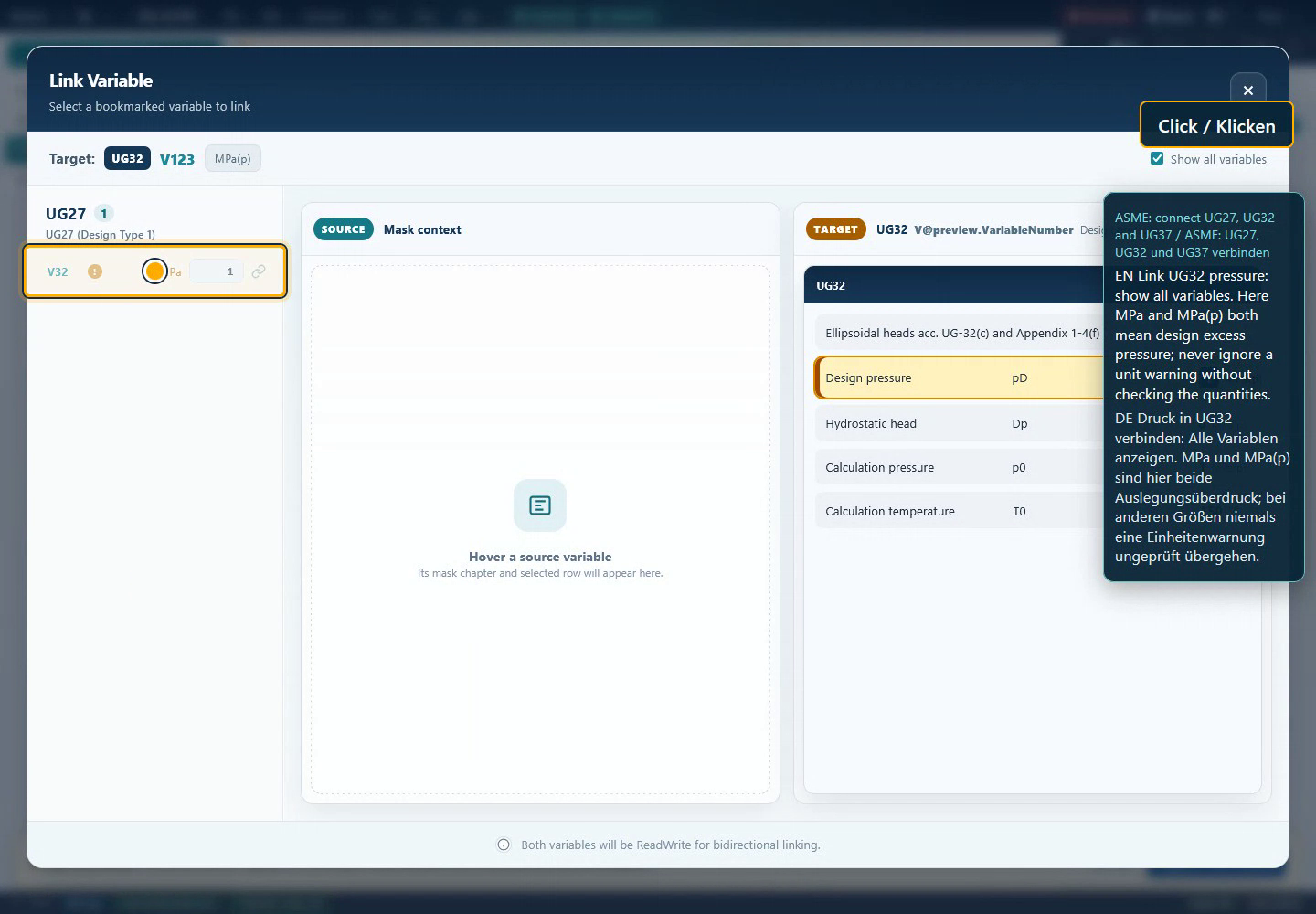
- Read target field and unit. This image shows UG32:V123; the target in the geometry scenario described here would be 2413:V5.
- Check source module and variable. The visible source UG27:V32 belongs exclusively to the ASME demo.
- An expanded variable list helps searching; it does not establish engineering compatibility.
Original frame from the approved ASME learning video recorded 6 September 2026, at 80 s. Pixels unchanged; highlights are HTML elements. Used explicitly as general operating context: no executed DIN/TRD image evidence is available. Open original · Image provenance.
Chapter 10301: choose geometry and cyclic-loading mode
The 301 family covers more than a plain cylindrical shell. The inspected desktop selector names six geometries; web registration provides nine masks for the first five geometry groups. The mapping below comes from source routing. Internal numbers help identify a saved case and are not instructions to edit project files manually.
| Geometry | Bauform(2) | With / without cyclic stressing |
|---|---|---|
| No openings | 1 | 301-1 / 301-12 |
| Inclined single branch | 2 | 301-2 / 301-22 |
| Perpendicular single branch | 3 | 301-3 / 301-32 |
| Multiple openings | 4 | 301-4 / 301-42 |
| Non-radial single branch | 5 | 301-5; no second mask pair |
| Single branch with internal cover | 6, desktop selector | Code enters branch 2 with an additional flag; no separate registered web case confirmed |
Bauform(3)=1 selects the cyclic-stressing variant in each mask pair, and Bauform(3)=0 the variant without it. The basic calculation here is “no openings, no cyclic stressing”, corresponding to mask route 301-12 and internal equation branch Bauform(1)=0. No nozzle dimensions or load-cycle spectrum are required for the pressure-wall arithmetic shown.
An existing opening or branch must not disappear simply because the plain-shell case is reused. Changing geometry changes material groups and result definitions: the code initialises additional materials for branches or reinforcement and, in certain branches, limits their allowable stress to that of the parent shell. After changing design type, therefore review retained material and allowance fields too.
Back to top ↑Chapter 11TRD 301: calculate operation and test together
The second normal case demonstrates pressure-wall arithmetic for a plain cylindrical shell. It is a deliberately specified numerical example without a real material dataset. K, K′ and safety factors are specified directly; no material suitability at a particular temperature is inferred. Sought fields remain free in the reference calculation.
| Fields | Input | Unit / meaning |
|---|---|---|
| V11 | 800 | mm, outside diameter |
| V2 / V3 | 40 / 60 | bar, operation / test separately |
| V7 / V8 | 220.5 / 1.5 | MPa / —, operation |
| V9 / V10 | 300 / 1.1 | MPa / —, test |
| V15 / V132 | 1 / 1 | Joint factors, operation / test |
| V13 / V14 / V117 | 0.5 / 1 / 0 | mm, c1 / operating c2 / test c2 |
| V4,V5,V19,V20,V29,V30,V115,V116,V26 | sought | Do not additionally constrain as inputs |
Source first forms σallow=K/S and σallow′=K′/S′. The operating branch, with general joint factor vN, calculates sv=dap/[(2σallow−p)vN+2p]. The test branch uses the same structure with its own values. Respective allowances are then added; V26 takes the larger result in the basic case considered. This explains the inspected implementation and does not replace the complete standard.
| Result | Operation | Test |
|---|---|---|
| Converted pressure | 4 MPa | 6 MPa |
| Allowable stress | 147 MPa | 272.72727273 MPa |
| Pressure wall excluding allowances | V29: 10.73825503 mm | V30: 8.70425321 mm |
| Requirement with allowances | V115: 12.23825503 mm | V116: 9.20425321 mm |
Thus V26=12.23825503 mm. Operation determines the calculated requirement in this example. A hypothetically chosen wall of 12.5 mm exceeds it by 0.26174497 mm. This difference is solely a margin against the wall requirement shown; it is neither a complete component assessment nor a margin against every other load case.
An actual program run must additionally record the real material definition, temperature and all remaining inputs required by the selected mask. The table above is complete for the equations evaluated here, but is not claimed to be a complete runtime state dump.
Back to top ↑Chapter 12Change 301 and identify the governing condition
Increase only operating pressure from 40 to 50 bar. Test pressure, strengths, joint factors and allowances remain unchanged for this controlled sensitivity calculation. This gives V29=13.37792642 mm and V115=14.87792642 mm. Test requirement remains 9.20425321 mm. The previously considered 12.5 mm now lies below operating demand. In a real change project, also establish whether the specified test condition or other constraints must change with operating pressure.
A second, separate experiment restores operation to 40 bar and increases only test pressure to 100 bar. Results are V30=14.40261866 mm and V116=14.90261866 mm. Testing now determines the larger requirement. This demonstrates why V26 must be assessed after calculating both branches. It does not recommend a test pressure of 100 bar.
| Condition | Operation with allowances | Test with allowances | Larger requirement |
|---|---|---|---|
| 40 / 60 bar | 12.23825503 mm | 9.20425321 mm | Operation |
| 50 / 60 bar | 14.87792642 mm | 9.20425321 mm | Operation |
| 40 / 100 bar | 12.23825503 mm | 14.90261866 mm | Test |
Compare more than the final wall. If V30 also changes in the first experiment, investigate an additional connection, coupled material change or another input. If V29 remains unchanged despite the pressure change, check whether the field is constrained, a converted representation has conflicting inputs, and calculation has completed. An unchanged number alone is not proof of a program defect.
Back to top ↑Chapter 13Invert 301 and interpret geometry correctly
The inverse check asks: which pressure produces a 12.5 mm requirement including c1+c2 in precisely the example's operating branch? With vN=1 and unchanged allowable stress of 147 MPa, the remaining pressure wall is sv=12.5−0.5−1=11 mm. Rearranging gives p=2σallow sv/(da−sv)=4.09885932 MPa, or 40.98859316 bar.
Substitute this pressure back into the forward expression: pressure demand becomes 11 mm, or 12.5 mm including allowances. Substitution is an effective check for mixed inside/outside diameters or a missing allowance. This is algebraic inversion, not a recorded inverse program run. Nor does it automatically determine the vessel's overall allowable pressure.
For an actual drawing comparison, separately document outside dimension, physical wall, deductions and the reference geometry used by the module. This handbook presents the source relationship openly; it neither corrects program labels nor claims that current mask interpretation has been resolved. The pure demand calculation above does not require V12 or V27 as inputs.
Back to top ↑Chapter 14Combine further assessments for a component
A sound calculation record connects components, load states and assessments. For a boiler with cylindrical shell, 301 may address internal pressure, 303 the dished head, and 305 a flat wall with its actual restraints. Vacuum requires a separate external-pressure task in 306 or another appropriate shell family. Simply reversing the pressure sign in an internal-pressure case is not a documented choice of method.
Cyclic stressing is described through its own loading history. 301A and 303A are separate modules in package configuration; choosing “with cyclic stressing” in a 301 mask does not automatically complete their separate application. This handbook establishes no automatic child-module call from 301 to 301A. Transfer load and geometry data only through an actually available connection or a documented manual handoff.
A flange joint requires at least matching flanges, gasket, bolts and load states in the same case. 2505, 250S and 25V identify different roles or source editions; 269X, SFLA and VFLA support related geometry selection. A geometrically matching standard flange does not automatically establish a tight joint for every fluid and temperature. Gasket parameters must use the definitions required by the selected method.
For supports, balance component, contents and additional loads before passing them into BEIN or TR28. BIEG supplies section information; BEBN concerns seismic loading. Axis directions, reference points and units are part of the handoff. RING additionally requires separate shell and jacket conditions, while BV29 requires the specific split or unsplit heat-exchanger design.
These associations are engineering workflows based on registered task descriptions. They do not promise a previously tested automatic module chain. For each handoff record the source, quantity, unit, target, reference condition and controlling input.
Back to top ↑Chapter 15Field reference for the three core modules
Field numbers help compare different language versions and old reports. Meanings were checked against field definitions and the equations evaluated. Units are those used for the quantities described here; a different display unit must be converted before transferring a number. The Use column distinguishes inputs, outputs, table values and unresolved interpretation questions.
301
| Field | Meaning | Example unit | Use |
|---|---|---|---|
| V1 | Design temperature t | °C | Design temperature from V101+V102 |
| V2 | Design pressure p | bar | Specified operating pressure of reference case |
| V3 | Test pressure P' | bar | Separately specified test pressure |
| V4 | Design pressure p | MPa | V2/10; alternative pressure representation |
| V5 | Test pressure P' | MPa | V3/10; alternative test-pressure representation |
| V7 | Nom design strength K | MPa | Specified operating design strength |
| V8 | Safety factor (operation) S | — | Operating safety factor |
| V9 | Nom design strength K' | MPa | Specified test design strength |
| V10 | Safety factor S' | — | Test safety factor |
| V11 | Outside diameter cylinder da | mm | Cylinder outside diameter |
| V12 | Inside diameter of cylinder di | mm | Inside dimension in equation system; observe V27 allowance convention |
| V13 | Allowance according to TRD 300 c1 | mm | Allowance c1, both load states |
| V14 | Allowance according to TRD 300 c2 | mm | Operating allowance c2 |
| V15 | Joint efficiency factor operation vN | — | Operating joint factor |
| V19 | Allowable stress (operating) sigmazul | MPa | K/S for operation |
| V20 | Allowable stress (test) | MPa | K′/S′ for test; English source label is imprecise |
| V26 | Req. wall thickness with allow. s | mm | Larger requirement from V115 and V116 in basic case |
| V27 | Existing wall thickness se | mm | Actual wall with a specific geometry/allowance relation |
| V29 | req. Wallthickness operating sv | mm | Operating pressure wall excluding allowances |
| V30 | req. Wallthickness test sv | mm | Test pressure wall excluding allowances |
| V101 | Operating temperature tb | °C | Operating temperature |
| V102 | Temperature allowance tz | K | Temperature allowance; difference, not absolute temperature |
| V115 | Req. wall thickness with allow. s(B) | mm | Operating requirement including c1+c2 |
| V116 | Req. wall thickness with allow. s(P) | mm | Test requirement including c1+c2(test) |
| V117 | Corrosion allowance (testing) c2 | mm | Separate test corrosion allowance |
| V132 | Joint efficiency factor test vNp | — | Separate test joint factor |
2413
| Field | Meaning | Example unit | Use |
|---|---|---|---|
| V1 | Design pressure p | bar | Pressure label; no complete pressure-demand calculation established in inspected equation block |
| V2 | Design pressure p | MPa | Second pressure representation; do not equate with bar |
| V3 | Design temperature t | °C | Temperature context; does not supply a missing material/pressure equation |
| V4 | Inside diameter di | mm | di=V5−2V8 in inspected source block |
| V5 | Outside diameter da | mm | Outside size; proposed link from 2448:V4 |
| V6 | Curvature diameter d | mm | Labelled curvature diameter; verify factor arguments separately |
| V8 | Nominal wall thickness s | mm | Nominal wall; not automatically local bend wall |
| V9 | Existing wall thickness inside sei | mm | Actual local intrados wall |
| V10 | Existing wall thickness outside sea | mm | Actual local extrados wall |
| V19 | Calculated wall thickness sv | mm | Straight reference demand; origin not calculated in inspected block |
| V21 | Ratio r/di | — | Labelled r/di; source forms V6/V4 |
| V22 | Ratio s/di | — | s/di: V8/V4 |
| V24 | Factor inside Bi | — | Intrados factor; establish validity before assessment |
| V25 | Calculated wall thickness si | mm | Intrados demand from V19×V24 |
| V28 | Factor outside Ba | — | Extrados factor; separate curve relation |
| V29 | Calculated wall thickness sa | mm | Extrados demand from V19×V28 |
| V34 | Factor (thin walled) Bi* | — | Thin-wall intrados factor; alternative relation |
| V35 | Factor (thin walled) Ba* | — | Thin-wall extrados factor; alternative relation |
| V51 | Nominal width | — | Nominal-size selection can determine outside size discretely |
| V52 | Please type in 3D ->3, 5D ->5 | — | 3D/5D table selection, source values3/5 |
| V53 | Radius of curvature r | mm | Curvature radius; source forms V6/2 |
2448
| Field | Meaning | Example unit | Use |
|---|---|---|---|
| V3 | row | — | Series 1/2/3; discrete standard-table selection |
| V4 | Outside diameter da | mm | Input: check actual outside diameter after table selection |
| V5 | Inside diameter di | mm | Output from outside diameter and actual wall |
| V6 | Standard wall thickness | mm | Standard wall from table; distinct from V8 |
| V8 | Existing wall thickness s | mm | Chosen/actual wall; explicitly specified in mass example |
| V9 | Tube length l | m | Length; input for total mass |
| V10 | Weight per unit length m | kg/m | Mass per unit length from the geometry used |
| V11 | Total mass M | kg | Total mass excluding attachments and contents |
Chapter 16Review, save and compare results
A useful report starts with the component, task and calculation basis. It then records complete inputs with units and origin, load states considered, governing result group and assessments still required separately. For a change, place initial and changed states side by side, including deliberately unchanged conditions.
For 2448 quantity checks, distinguish table wall, actual wall, kg/m and total length. For 301, operation and test must remain visible; a report should not show only V26 without its two contributing results. For 2413, the unresolved curvature definition is additionally relevant. A report retaining that question must not suggest that bend-strength assessment is complete.
Save an actual program run as its own project and preserve the unchanged starting state. A reopened project becomes a useful reference only after checking module instances, design types, material definitions, constraints and connections. Record the runtime actually used; a current handbook edition does not retrospectively update an earlier saved calculation engine.
Handbook search filters chapters using multiple search words. A chapter anchor from the contents or a direct link makes its target visible again. Printing includes chapters hidden by search. DE and EN have identical chapter anchors; the entry page follows the application's global language. Directly opened DE/EN files can also be read and searched locally.
Back to top ↑Chapter 17Troubleshooting and common questions
Which module should I start with for a seamless tube?
For dimensions and mass, 2448 is the task explained here; its source recommends successor 10220. Pressure strength belongs in a strength method appropriate to the project basis. Selecting a tube-table entry does not approve its wall.
Why does 2448 change my diameter?
A table branch can move the entry to the next supported standard dimension. Read the actual V4 and V6 after series and size selection. In the analytical case, V8 is additionally specified as a separate actual wall.
Is V6 in 2448 the same as V8?
V6 is standard wall from the table; V8 is actual wall. They may be equal but remain different fields serving different purposes. The mass formula uses V8.
Why does another tube length not change bend demand?
The proposed connection transfers outside diameter and wall. Length is neither transferred quantity. It changes total tube mass, but not the bend section geometry considered here.
Can I complete 2413 merely by entering pressure and temperature?
That was not established for the inspected source block. The bend method uses V19 as reference demand without deriving it from pressure and material in this group. Establish the origin of V19 and the curvature definition.
Is a factor of 999 valid?
The inspected 2413 helpers return 999 for certain invalid conditions. Treat it as a reason to check inputs and applicability, not as a reliable physical quantity.
Can 301 test pressure be derived from operating pressure?
The reference specifies both separately. It contains no general rule for setting test pressure. A project-defined ratio must be documented as an additional assumption.
Why does 301 show several walls?
V29 and V30 are pressure demands without allowances. V115 and V116 include their respective allowances. In the basic case considered, V26 is the maximum of these two complete requirements. V27 denotes actual wall.
Can I use identical material values for test and operation?
Only when justified for the case. The program keeps strengths, safety factors, joint factors and some allowances separate. Identical numbers must be a deliberate decision.
Why is my inside-diameter entry unexpected?
In 301 check the specific relation between V11, V12, V27 and allowances. The source basic case uses V27=(V11−V12)/2+c1+c2. Avoid inadvertently adding an allowance twice to a directly measured finished dimension.
Does a passed shell case cover the vessel?
It supports conclusions about that specific shell case. Heads, openings, external pressure, bolts, supports and cyclic loading may require further cases. The package map helps assign them.
Are BOG and 2413 interchangeable?
Both concern bends but name different references. Design type, curvature definition and reference-demand definition must be checked for each method. Identical numeric fields do not establish equivalence.
Is the inverse pressure an allowable operating pressure?
Here it is solely an algebraic limit of the operation branch considered, with joint factor 1 and fixed strengths. It does not assess testing, additional loads or other components.
What does the image showing UG27 and UG32 represent?
An unchanged connection dialog from an approved ASME demo. Its caption explains general operating context. It establishes neither a DIN/TRD mask nor an executed DIN/TRD connection test.
Can the example file be opened as a SOL project?
No. The JSON file contains the complete analytical case specification. No real DIN/TRD project archive is supplied as a verified example for this handbook. Create a separate project for your own run.
How should I compare an old calculation with a new one?
First preserve the old report with inputs, results and references. Then compare geometry, strengths, allowances and result definitions for each load case. A lower number on another basis is not automatically an improvement.
Chapter 18Sources, evidence level and limits
Package membership, module tasks and registered references were recorded on 7 September 2026 from web configuration and module metadata. Core review covers field definitions, registered masks and selected calculation/routing blocks in 2448, 2413 and 301. The source snapshot records repository revisions and hashes of inspected files. It contains no customer project content.
The analytical cases explicitly declare source-only evidence in machine-readable form. The accompanying recalculation script can be run with Node.js; it evaluates only the described formulas and does not launch SOL ALPHA. Documented results were checked using these formulas. This establishes reference arithmetic, not runtime parity or complete rules validation.
The real screenshot comes from an approved learning video and is labelled solely as general operating context. Original ASME labels, notices and pixels remain visible; additional numbered highlights are overlaid in HTML. Origin, time and SHA-256 are stored separately. This edition contains neither a substitute screenshot presented as DIN/TRD nor an invented project archive.
External primary sources were used for bibliographic distinctions: DIN 2413:2011-06, DIN 2413:2020-04, DIN 2448:1981-02, and draft DIN 2505-1:1990-04. These product pages do not replace standard texts. Stated status refers to checks on 7 September 2026.
Remaining gaps are an executed DIN/TRD normal/change/reopening run, clarification of 2413 curvature interpretation and the complete V19 calculation route, and runtime checks of the other package variants. The package map explains their tasks; it does not replace their individual detailed module handbooks.
Back to top ↑