Further EN standards – Component calculations
Select, calculate and traceably review flanges, gaskets, valves and boiler components.
No chapter found. Try another search term.
Chapter 01Choosing the appropriate calculation
This package brings together calculations for flanges, gaskets, valves, boiler components, transport tanks and further specialised tasks. “Further EN standards” is an organisational grouping. Its modules use different standards and editions. Start with the component and the required assessment: selecting dimensions for a standard flange answers a different question from examining a bolted joint under assembly, temperature and pressure.
For a new flange joint, a typical workflow starts with geometry in 1092, adds a suitable gasket from 1514/151N, and proceeds to joint calculation in 159H. Its load cases are handled in 159S. For the pressure-retaining wall of a valve casing, choose the appropriate variant within 516A–516D. A boiler end belongs in the relevant KAP family. The package map accounts for all 25 configured members and identifies the three KAP tokens currently unresolved in the Web module registry.
The examples connect concrete inputs with traceable checks. Two archived regressions provide historical references; wall-thickness variants are calculated independently from the inspected source branch. No new EN module calculation was executed for this edition. The genuine program image explains the shared link dialog and is identified as an ASME example capture. This distinguishes values you can check from operating procedures still to be executed in your installation.
Back to top ↑Chapter 02All 25 modules and their roles
The following overview reflects the actual configured package membership. Some tasks also belong conceptually to other packages: E168 covers saddle supports under EN 13445, while BULK addresses bulk-solid loads under EN 1991-4. These overlaps do not establish additional or equivalent calculation routes. Use the module token together with its full title, design variant and the standard edition agreed for the project.
| Module | Task | Scope and selection guidance | Source edition / registry |
|---|---|---|---|
| 1092 | Select standard flange | Related flange dimensions and pressure-temperature data. Distinguish PN and PS; V160 is an internal identifier. | DIN EN 1092-1: 2018-12 Registered |
| 1514 | Non-metallic flat gasket | Dimensions and offered gasket properties. Nominal annular area is not automatically effective contact area. | DIN EN 1514-1: 1997-08 Registered |
| 151N | Gasket using manufacturer data | Gasket geometry and appropriate manufacturer assignment. Retain product, temperature and valid dataset. | DIN EN 1514-1: 1997-08 & manufacturer specification Registered |
| 159H | Calculate flange joint | Parent module for flanges, bolts and gasket, including assembly and load cases. | DIN EN 1591-1: 2014-04 Registered |
| 159S | Joint load cases | Testing and operating states managed by the parent; preserve relationships and shared geometry. | DIN EN 1591-1: 2014-04 Registered |
| 220 | Steel pipe dimensions and mass per length | EN 10220: dimensional and mass basis. Does not independently establish pressure strength. | DIN EN 10220:2003-03 Registered |
| 516A | Valve bodies and circular flanges | Select body shape first; detailed teaching case covers only a cylinder without openings. | DIN EN 12516-2: 2022-08 Registered |
| 516B | Further flanges and closures | Oval/rectangular flanges, bolts and self-sealing closures according to the selected variant. | DIN EN 12516-2: 2022-08 Registered |
| 516C | Ends, spherical shells and plates | Dished ends and applicable circular/annular plates. Check boundary conditions and loaded side. | DIN EN 12516-2: 2022-08 Registered |
| 516D | Bolted covers | Cover plates with or without an opening or nozzle; consider offered gland loads. | DIN EN 12516-2: 2022-08 Registered |
| ADR | Transport tank: wall and pressure | EN 14025 with ADR/RID references. Partial tank assessment; document the applicable transport edition. | DIN EN 14025: 2018-09 & ADR & RID Registered |
| AUZY | Water-tube boiler openings | EN 12952: openings and branches in cylinders, including different reinforcement and connection forms. | DIN EN 12952-3/8: 2023-01 Registered |
| BULK | Bulk-solid silo loads | EN 1991-4: loading basis. Assign load distribution, wall friction and filling/discharge state to structural assessment. | DIN EN 1991-4: 2010-12 Registered |
| DECK | Tank covers and bolt area | Flat and dished covers in the described EN 14025 scope. Attachment and load case are part of the geometry. | DIN EN 14025/6.3.6: 2018-09 Registered |
| EF01 | Plate flange type 01 | Older EN 1092-1:2002 route for a plate flange; do not interpret it as a welding-neck flange. | DIN EN 1092-1: 2002-05 Registered |
| EF02 | Loose flange type 02 | Older EN 1092-1:2002 route. Assess the loose flange together with its associated collar. | DIN EN 1092-1: 2002-05 Registered |
| EFLA | Further circular steel flanges | Older EN 1092-1:2002 route with several flange/collar forms. Not a substitute for 159H without checking the assessment objective. | DIN EN 1092-1: 2002-05 Registered |
| KAP1 | Isolated openings in flat boiler ends | EN 12953-3 chapter 11 according to the module headline. Distinguish isolated openings from groups. | 11 Isolated openings in boiler flat end plates -- DIN EN 12953-3: 2016 Registered |
| KAP2 | Unpierced tubes and tubeplates | EN 12953-3 chapter 12 according to the headline. Tube and boundary conditions require system-specific inputs. | 12 Unpierced tubes and tube plates -- DIN EN 12953-3: 2016 Registered |
| KAP3 | Furnace tubes | Described EN 12953-3 chapter 13 route; Web registration unresolved. Treat external pressure/stability explicitly. | Furnaces tubes, furnace components and reversal chamber of cylindrical form subjected to external pressure -- DIN EN 12953-3: 2016 Web registration unresolved |
| KAP7 | Cylindrical boiler parts under internal pressure | Described EN 12953-3 chapter 7 route; Web registration unresolved. | 7 Cylindrical shells under internal pressure -- DIN EN 12953-3: 2016 Web registration unresolved |
| KAP8 | Boiler openings and branches | EN 12953-3 chapter 8 according to the headline. Record variant, reinforcement and connection orientation. | 8 Openings and branches in cylindrical shells -- DIN EN 12953-3: 2016 Registered |
| KAP9 | Boiler ends | EN 12953-3 chapter 9 according to the headline. Source variants include dished ends and flat unstayed closures; match variant and attachment. | 9 Ends -- DIN EN 12953-3: 2016 Registered |
| KAP0 | Stayed flat walls | Described EN 12953-3 chapter 10 route; Web registration unresolved. Stay arrangement belongs to the structural model. | 10 Supported flat plates -- DIN EN 12953-3: 2016 Web registration unresolved |
| E168 | Horizontal vessels on saddles | EN 13445-3/16.8: distinguish type-A conditions from stress assessment; consider weight and pressure together. | DIN EN 13445-3/16.8: 2016-12 Registered |
“Registered” means matched against the available Web module descriptions. Registration establishes neither your licence nor execution of every legacy variant. KAP3, KAP7 and KAP0 remain visible in the map but have no corresponding current Web registry entry. Establish a documented available calculation route for these tasks before relying on them for project approval. This overview does not replace individual instructions for every subvariant.
Back to top ↑Chapter 03Establishing edition and calculation scope
Record the governing standard and edition in the project header, together with the modules used. In the inspected sources, 1092 specifies DIN EN 1092-1:2018-12. EF01, EF02 and EFLA instead carry the older 2002-05 edition. Similar component sketches therefore do not justify an unchecked substitution. 159H/159S specify DIN EN 1591-1:2014-04, whereas 516A–516D specify DIN EN 12516-2:2022-08.
At the editorial review on 7 September 2026, DIN Media lists DIN EN 1591-1:2026-02 as replacing the 2014-04 edition. The new DIN edition is the German version of EN 1591-1:2024; distinguish the DIN publication date from the year of the European edition. This catalogue information does not establish a corresponding change in the inspected module. For DIN EN 12516-2, the catalogue identifies the 2022-08 edition. Check the actual product version and contractual calculation basis before attributing results to a standard edition.
The same applies to material standard, product form, temperature range and loading category. A material number alone does not define a complete strength dataset. Explicitly document differences between project requirements and module version. Do not rename a report or its source attribution to make an older calculation appear to implement a newer edition. Any necessary additional assessment belongs in the verification as a separate, traceable element.
Back to top ↑Chapter 04Building a new example systematically
- Create a separate teaching project and select the module by token and full description. Start with one component; add links only after obtaining a checkable individual calculation.
- Select calculation category and design variant first. In 516A, V228 and V229 distinguish valve-casing calculation from the flange route and identify cylindrical, spherical and other bodies.
- Set units and language. Record whether pressure is expressed in bar or MPa and whether it is gauge or absolute pressure. Units are part of the value.
- Specify temperature and material with product form. Inspect the strength values and safety factors actually assigned for operation and testing.
- Add geometry, allowances and loads. After each input, check dependent dimensions, visible conditions and calculation messages.
- Save the complete starting state. Change exactly one quantity in the next step and compare results against the starting case.
If an expected field is hidden, first inspect the selected variant and its controlling selectors. A field number from another variant does not prove the quantity is required here. The field reference deliberately covers an inspected core. The complete mask inventory in the reference download preserves additional conditional fields and their provenance.
Back to top ↑Chapter 05Reading flange geometry: 1092
1092 selects related standard dimensions and the associated pressure-temperature rating. V1 is PN and V2 is DN. DN is a nominal size designation; calculation requires actual connection, inside and outside diameters. In the historical example, DN 200 corresponds to connection dimension A = 219.1 mm and an internal connection dimension of 206.5 mm. Entering “DN = inside diameter” would be incorrect.
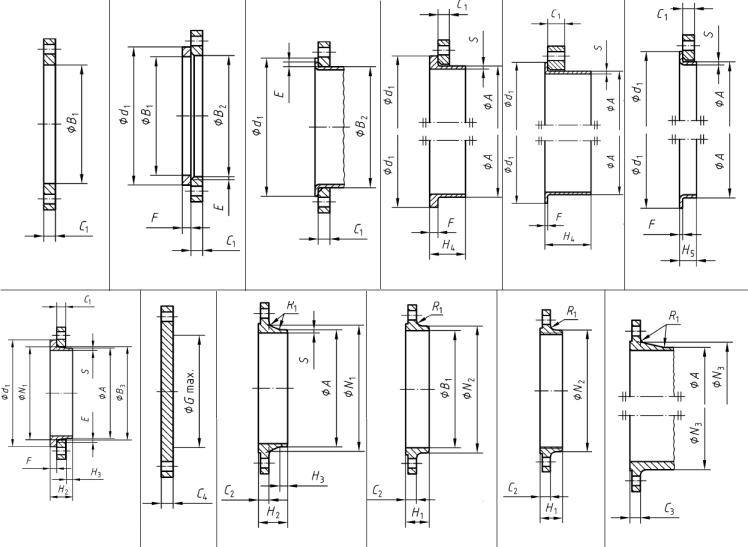
The following graphic is preserved unchanged from the actual 1092 mask. It shows several flange and collar forms. Dimension symbols depend on the form: C1, C2 and C4 are not interchangeable, nor are H1, H2 and H3. Compare the sketch with your drawing before transferring a dimension manually. The third lower detail shows a hub geometry and the references C2, H2 and H3.
 123
123- Flat section with thickness C1; do not confuse it with C2 of a hub flange.
- Blind closure with thickness C4; opening and load path differ.
- Hub geometry with C2, H2 and H3: transfer the dimensional references together from the drawing.
Unchanged embedded program artwork; not a capture of an executed calculation. Open original
In the inspected program, V160 is a database identifier. The interface constructs labels such as “Type09” from it. Do not interpret that label as standard flange type 09 without checking. The example therefore records the exact stored selector V160 = 9; identify the construction through its sketch, resulting dimensions and actual standard type. After changing type, review the connection, facing, bolt pattern and thickness together.
Back to top ↑Chapter 061092 example: PN 10 at 120 °C
The archived example dated 10 August 2026 uses V160 = 9, DN 200, PN 10 and 120 °C. Its material is 1.4571(P), stored under database identifier 1232 at that time. The material description specifies hot-worked plate and older EN 10028-7/AD W2 datasets. That database identifier is an archive reference, not a universal material identifier across installations.
| Quantity | Archive value | Archive status |
|---|---|---|
| V1 / V2 | PN 10 / DN 200 | Inputs |
| V160 / V31 | 9 / 120 °C | Inputs |
| V3 / V11 | 219.1 mm / 6.3 mm | Derived defaults: A / S |
| V5 / V6 / V7 | 340 / 24 / 295 mm | Derived defaults: D / C2 / K |
| V18 / V19 / V20 | 8 / 22 mm / M20 | Derived defaults: count / hole / thread |
| V30 | 9.92 bar | Derived default PS |
| V22 | 206.5 mm | Expected test output; A − 2S independently confirmed |
The reference explicitly distinguishes inputs, derived defaults and expected test results. PS = 9.92 bar appears among the derived defaults. It is not a newly observed calculation output for this handbook. An independent geometric check gives A − 2S = 219.1 − 2 × 6.3 = 206.5 mm, matching archived expected V22. This checks the dimensional reference, not the entire flange strength assessment.
For your own replay, first select the same combination, DN and PN, then temperature and the suitable material actually available. Inspect every tabulated dimension before using the connection further. With a different database or standard edition, do not assume an identical identifier or PS value. Record the difference together with product and data versions and establish its cause.
Back to top ↑Chapter 07Distinguishing PN, PS and temperature
PN is a pressure designation. The usable pressure at a particular temperature and material assignment is not obtained simply by adding “bar”. In the historical PN 10 example, PS is stored as 9.92 bar at 120 °C. This difference illustrates why the PN 10 marking alone does not assess a joint. The limits and results of the full joint assessment must also be considered.
The inspected 1092 source route considers PN, material group and temperature. It also distinguishes the thickness associated with the flange form and evaluates the corresponding pressure-temperature data. The applicable data route interpolates between available temperature points. Missing required assignments can clear PS. A blank result is therefore neither a zero-bar pressure approval nor a reason to retain the old value manually.
As a change exercise, increase only temperature in a copy and record the material group, relevant thickness and PS before and afterwards. This handbook supplies no invented new table value: the applicable database must provide it. Check that the result lies within its valid temperature domain and that material properties in 159H have also been updated. A temperature change in one module does not establish a consistent temperature case throughout the project.
Back to top ↑Chapter 081514 and 151N: dimensions and gasket data
A suitable gasket must geometrically match the facing, bolt pattern and intended construction. 1514 covers non-metallic flat gaskets under the EN 1514-1 edition stated in its source. 151N adds selection using manufacturer specifications. Geometric fit is only the beginning: material, thickness, temperature, medium and required tightness determine which substantiated properties can be used in the flange calculation.
In 1514, check at least V2 DN, V3 inside diameter, V5 outside diameter and V6 thickness. V13 carries operating temperature, V14 pressure and V15 PN. The legacy definition annotates V15 with “bar”; physically PN remains a pressure designation, not an allowable pressure at every temperature. Further fields concern deformation and loading properties. Do not transfer a value merely because its symbol looks similar: a legacy gasket factor is not automatically the quantity required by a newer EN 1591 edition. Obtain a dataset appropriate to the gasket, test method and temperature.
For a geometric check with freely selected teaching dimensions do = 260 mm and di = 220 mm, the nominal annular area is π(do² − di²)/4 = 15079.64 mm². This is expressly not the calculated effective gasket area AGe from 159H. Its effectively loaded region can differ from the nominal area. Use this calculation to discover an incorrect diameter or radius transfer, not to replace the contact assessment.
Back to top ↑Chapter 09159H: a complete flange-joint workflow
159H considers the interaction of both flanges, bolts and gasket. This includes assembly, operating and test loads, and the components’ differing deformations and temperatures. Selecting a standard flange supplies geometry; it does not replace this joint assessment. Start with a sketch identifying flange 1, flange 2, gasket, bolts and connected shells.
- Select the constructionally appropriate flange type for each side. Establish which geometry comes from standard selection and which dimensions are independently specified.
- Assign material and temperature to each component. A hot flange joint can have different bolt, flange and gasket temperatures.
- Transfer gasket dimensions and an appropriate property dataset. Check bolt count, load-carrying area and thread designation.
- Define assembly conditions and individual operating and test cases. Record additional forces and moments with signs and reference points.
- Select the bolt-force strategy and calculate the joint. Read each component assessment and the governing-condition text.
- Change one load case and verify that the intended dependent results update. Save the full assessment including associated load cases.
The available Web compatibility tests also describe transfer of an EN 1092 selection to an associated 1092 child module. This does not imply arbitrary automatic links between independently created chapters. Inspect the relationship actually generated by the parent before placing a second dimensional selection alongside it as an assumed substitute.
Back to top ↑Chapter 10159S: keeping assembly, operation and testing distinct
159S is a load-case module associated with 159H. The inspected compatibility tests expect separate internal chapters for testing and operation and check unique parent-child relationships. V4 distinguishes the load-case category; V10 carries its description. Do not create or copy such internal chapters as arbitrary independent components. Their relationship to the main module determines shared geometry and data.
A learning matrix can start with three clearly described states: assembly without operating internal pressure, operation at the specified temperature and load, and testing at its prescribed pressure and temperature. This matrix is preparation, not a newly executed 159H calculation. For each state, record pressure definition, component temperatures, external loads and the criterion to be assessed. A test-pressure factor alone does not establish every testing boundary condition.
After calculation, compare bolt, gasket and both flange utilizations. Record the governing component together with its load case. Low bolt utilization during operation does not establish that the gasket avoids overload during assembly. Likewise, a satisfied testing criterion does not replace tightness assessment in hot service. The report must combine these conclusions while keeping their meanings distinct.
Back to top ↑Chapter 11Specified and automatically determined bolt force
Specifying bolt force and automatically determining the required force answer different design questions. A specified force assesses a selected assembly state. Automatic determination asks the implemented calculation route to establish a force, after which you must inspect its limiting conditions. Record the selected strategy as well as the numerical value.
The available Web compatibility test switches between these states through the special menu. In specified mode it enters 159H V64 = 200000 N, labelled FB0,spec. It then returns to automatic mode and checks the limiting description. This is an evidenced test procedure from the source repository, not a 200 kN assessment rerun for this edition and not a recommended assembly force.
For your own change exercise, first save the automatically determined state. Switch to the offered specified-force mode, enter a justified comparison value and reread every component assessment. Finally switch back and inspect force, visible specification and limiting description. Before dividing by bolt count, explicitly establish whether the field denotes total or individual force. A resulting assembly instruction also requires an appropriate treatment of tightening method, friction and scatter.
Back to top ↑Chapter 12Transferring quantities between modules
An engineering sequence is not yet a saved program link. Before linking, prepare a transfer list: source, target, physical quantity, unit, pressure or dimensional reference, and responsibility for changes. Transfers from 1092 to 159H may concern flange dimensions; those from 1514/151N concern gasket geometry and suitable properties. First determine which transfers are already managed by the parent module and its children.
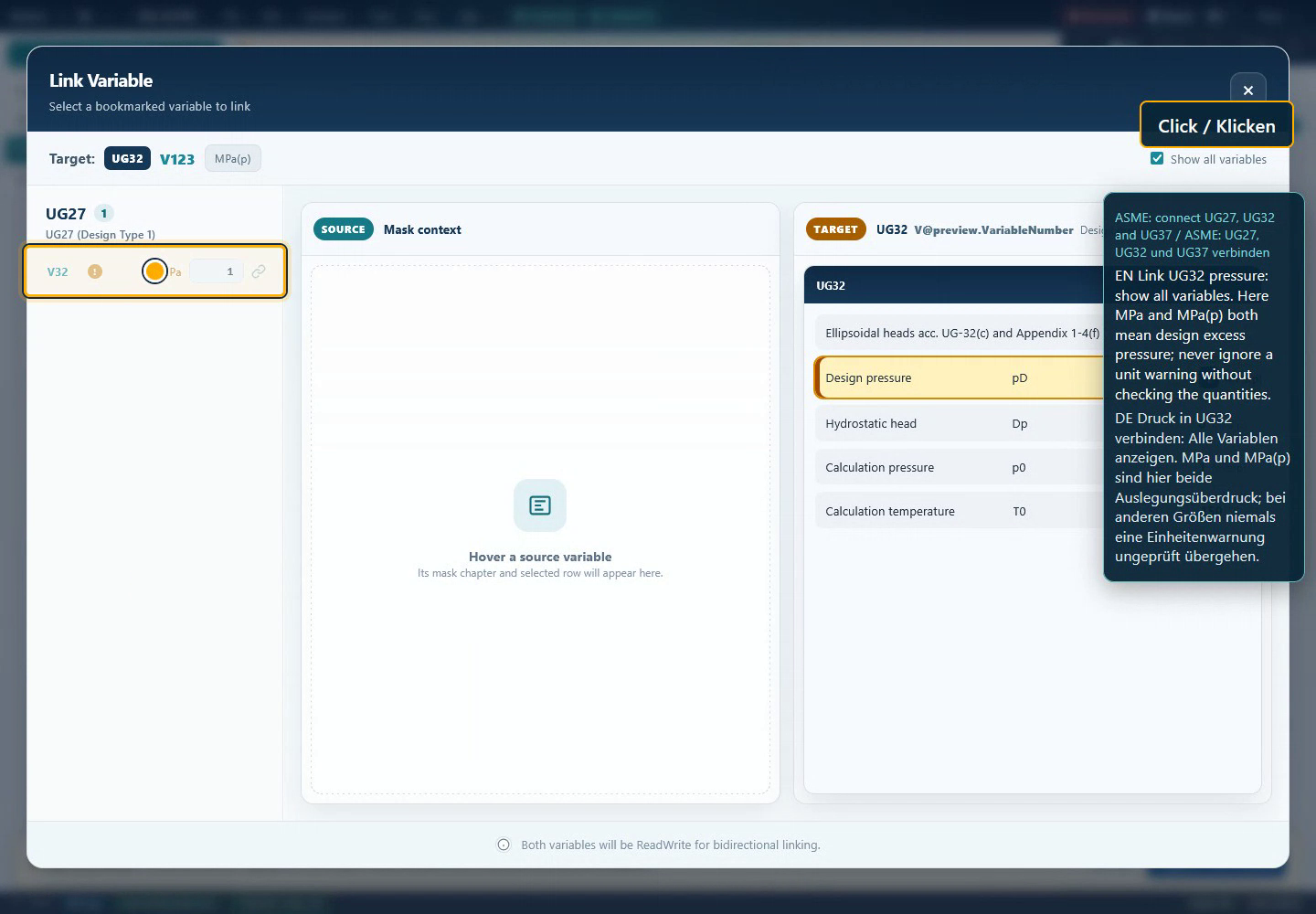
The unchanged image below shows the genuine shared link dialog in a historical ASME teaching workflow. ASME module names remain visible. It explains only the common controls: target at the top, source variable on the left, unit warning and indication of editing at both ends. It does not show an executed 1092, 159H or 516A connection.
 123
123- The target identifies module, field and unit. Read these three items together.
- The source also displays a unit warning. Check quantities and pressure reference before linking.
- ReadWrite at both ends: changes can propagate back through the link.
Unchanged original frame at 80 s, ASME teaching video dated 6 September 2026; build not independently identified. Existing ASME text and video annotations remain visible. Open original
Select a source only after comparing the quantities. Identical units do not make outside diameter and bolt-circle diameter equivalent; similar pressure labels do not establish the pressure reference. The visible dialog indicates ReadWrite for both variables. Therefore consider changes at either end and check their effect in a copy. For an independent comparison, deliberately remove the relevant link or use a separate project state. Do not overwrite a linked value on the assumption that only one module will change.
Back to top ↑Chapter 13516A to 516D: choosing the valve component
The family distributes different pressure-retaining valve components across several modules. 516A handles bodies and circular flanges. 516B includes oval and rectangular flanges, bolts and self-sealing closures. 516C concerns dished ends, spherical shells and certain flat circular or annular plates. 516D addresses bolted covers and related plate and gland loads. The exact variant determines geometric and loading assumptions.
The worked example uses only 516A, variant 11, with V228 = 1 for casings under predominantly static loading and V229 = 1 for a cylindrical body without openings. It does not assess a branched casing, spherical body or rectangular section. Current masks offer selectors within this route; additional archived mask files do not automatically establish independently startable current Web modules.
For a real valve, inspect every pressure-retaining region: wall, transitions, openings, flanges, covers and fasteners. An adequate cylindrical wall can coexist with an inadequate cover. A result for predominantly static loading also does not automatically cover every cyclic load. Maintain a component list identifying the responsible module and remaining assessment scope for each part.
Back to top ↑Chapter 14Specifying the complete 516A example
The reference case comes from a regression dated 27 June 2026. Its large dimensions and low pressures serve a readily checkable calculation here; they are not a construction recommendation for an actual valve. The outside reference is explicit: V2 = 1200 mm, actual wall V9 = 5 mm, giving inside diameter V27 = 1190 mm. Ratio V25 = 1200/1190 ≈ 1.008403 is below the inspected branch limit of 1.7.
| Field | Input | Meaning |
|---|---|---|
| V228 / V229 | 1 / 1 | Predominantly static cylindrical casing without openings |
| V2 / V9 | 1200 mm / 5 mm | Outside diameter / actual wall |
| V24 | 120 °C | Operating temperature |
| V14 / V11 | 0.1 MPa / 0.3 MPa | Operating / test gauge pressure |
| V6 | 1 | Joint coefficient |
| V7 / V8 | 0.3 mm / 0 mm | c1 / c2 |
| V4 / V5 | 218 N/mm² / 1.5 | K / S |
| V17 / V15 | 260 N/mm² / 1.05 | K′ / S′ |
| V22 | 1.4571(P), 1232 | Historical material assignment, no new query |
V14 carries the design pressure for the operating case, referred to here as “operating pressure”. V14 = 0.1 MPa corresponds to 1 bar gauge; V11 = 0.3 MPa corresponds to 3 bar test gauge pressure. Do not interchange the fields or replace the specified design pressure with an arbitrary instantaneous operating value. Allowances c1 = 0.3 mm and c2 = 0 are added when determining required thickness in this branch. Do not replace the actual 5 mm wall with the calculated minimum. It represents existing geometry and contributes to its diameter ratio.
The historical material dataset supplies K = 218 N/mm² and S = 1.5 for operation, and K′ = 260 N/mm² and S′ = 1.05 for testing. These give f = 145.333333 N/mm² and f′ = 247.619048 N/mm². The independent teaching calculation explicitly fixes these numbers. It claims neither a current material-database query nor approval of this material for a particular component.
Back to top ↑Chapter 15Independently checking operation and testing
For the selected cylindrical branch, source cases 1105 and 1106 first form the pressure-dependent wall contribution and then add allowances. With outside diameter D, pressure p, allowable stress f and joint coefficient k, the independently checked relationship is:
e = Dp / [(2f − p)k + 2p] + c1 + c2.
Operation uses p = V14 and f = V26; testing uses p = V11 and f = V23. In the inspected source case, common result V1 is the maximum of V18 and V19. This relationship is limited to the described branch. For larger diameter ratios the source uses another relationship; a sphere or flange cannot be assessed using this cylindrical equation.
| Case | p / p′ [MPa] | eB [mm] | eP [mm] | Maximum [mm] | Governing |
|---|---|---|---|---|---|
| Starting case | 0.1 / 0.3 | 0.712702 | 1.026483 | 1.026483 | Testing |
| Change operating pressure | 0.2 / 0.3 | 1.125120 | 1.026483 | 1.125120 | Operation |
| Change test pressure | 0.1 / 0.6 | 0.712702 | 1.752087 | 1.752087 | Testing |
The starting case gives eB = 0.712702 mm and eP = 1.026483 mm. Testing therefore governs. The independently calculated values agree with the archived regression expectations within 0.000001 mm. This checks the formula and archived example, not a new end-to-end module run. The actual 5 mm wall exceeds this pressure-related result; further minimum thicknesses, geometric conditions and component assessments remain separate checks.
Back to top ↑Chapter 16A change and a switch of governing case
For the first analytical variant, increase only operating pressure from 0.1 to 0.2 MPa. Keep temperature, strengths, geometry, allowances and test pressure fixed for this isolated investigation. Required operating wall rises to 1.125120 mm; test wall remains 1.026483 mm. Operation now governs. Comparing only the previously governing test result would miss this change.
For the second variant, double only test pressure from 0.3 to 0.6 MPa and restore the original operating pressure. Test wall rises to 1.752087 mm while operating wall remains 0.712702 mm. These variants are deliberately separate. In an actual project, a requirement may link test pressure to operating pressure, in which case the entire intended load-case change must be recalculated.
To repeat this in your installation, save each state with a clear description and document V14, V11, V18, V19 and V1. Also inspect whether the change triggers new material, temperature or geometric conditions. This chapter’s values come from independent source arithmetic with fixed properties. If module values differ, compare actual inputs and active branches before classifying the difference as a calculation defect.
Back to top ↑Chapter 17Inverse calculation: pressure for a specified wall
The same relationship supports a precisely bounded inverse teaching question: which operating pressure produces a required 5 mm wall with unchanged properties? First subtract allowances once: er = 5 − 0.3 − 0 = 4.7 mm. Algebraic rearrangement gives:
p = 2fker / [D − er(2 − k)].
With D = 1200 mm, f = 218/1.5 N/mm² and k = 1, pressure is 1.142920885 MPa, or 11.42920885 bar. Substituting it back into the forward equation returns exactly 5 mm. It also agrees with the historical expected 516A V160 value of 1.1429209 MPa. This connects algebraic inversion, forward verification and the archived reference.
The target is solely the boundary of this operating-wall relationship. It is not a new allowable operating pressure for the complete valve. Test pressure, minimum wall, openings, covers, flanges, temperature limits and further applicable criteria still require assessment. Actual inverse operation also requires an explicit change of input/output roles: required thickness cannot simultaneously be a fixed input and an unknown result. This handbook verifies the algebra, not a newly executed inverse operating sequence.
Back to top ↑Chapter 18Boiler components: AUZY and the KAP family
Select boiler modules by component and governing boiler standard. AUZY belongs to the EN 12952 water-tube boiler area and addresses openings and branches in cylindrical parts. Its description distinguishes, for example, unreinforced and reinforced openings, oblique or non-radial connections, and adjacent openings. An isolated radial opening differs geometrically and in interaction effects from a group of openings.
The KAP module headlines assign their tasks to the corresponding EN 12953-3:2016 shell-boiler sections. KAP1 concerns isolated openings in flat ends, KAP2 unpierced tubes and tubeplates, KAP8 openings and branches in cylindrical shells, and KAP9 boiler ends. KAP3, KAP7 and KAP0 are configured but unresolved in the inspected Web registry. KAP3 describes furnace tubes, furnace components and cylindrical reversal-chamber shells under external pressure; KAP7 cylindrical shells under internal pressure and KAP0 stayed flat walls.
For each task, prepare a drawing identifying edge restraint, opening spacing, effective lengths and the loaded side. Internal and external pressure are separate assessment problems. A tubeplate needs the tube and boundary conditions of its actual system; do not substitute an isolated plate result without checking them. This chapter maps the calculation routes. It claims neither an executed KAP variant nor a complete boiler design.
Back to top ↑Chapter 19Transport tanks, bulk solids and saddle supports
ADR, within its described module scope, addresses minimum wall thickness and design pressure of transport tanks with references to EN 14025 and ADR/RID. DECK concerns flat or dished tank covers and required bolt area. Suitability of a transport tank extends beyond these two strength tasks. Substance assignment, construction and applicable transport requirements must match actual service. UNECE publishes ADR 2025, whose amendments apply from 1 January 2025. The module source separately cites an older EN 14025 edition. Record these references distinctly.
BULK determines bulk-solid silo loads under the EN 1991-4 edition stated in its source. These loads feed subsequent structural and wall assessments. Filling, discharge, wall friction and material properties cannot be replaced by a generic liquid column. Draw load direction and reference height for transferred loads; one maximum value does not automatically describe spatial distribution.
E168 examines horizontal vessels on saddles under EN 13445-3 section 16.8. Its description distinguishes conditions for type-A saddles without stress analysis from assessment of shell and saddle-region stresses. Satisfying a condition in a simplified route does not establish suitability for arbitrary saddle geometries. For further detail and integration with vessel calculation, use the EN 13445 handbook. The FE modelling route is explained separately in the FEA Toolbox handbook.
Back to top ↑Chapter 20Field reference for the detailed workflows
This reference connects the field identifiers used in the chapters with their engineering meaning. The same number means different things in different modules: 1092 V1 is PN, whereas 516A V1 is required wall thickness. Always identify the module together with the field. Units come from the inspected module definition; the visible interface may offer another permissible display unit.
| Module / field | Meaning | Unit / type |
|---|---|---|
| 1092 V1 | PN / pressure designation | – |
| 1092 V2 | DN / nominal size | – |
| 1092 V3 | Connection dimension A | mm |
| 1092 V5 | Flange outside diameter D | mm |
| 1092 V6 | Flange thickness C2 | mm |
| 1092 V7 | Bolt-circle diameter K | mm |
| 1092 V8 | Total length H2 | mm |
| 1092 V10 | Hub diameter N1 | mm |
| 1092 V11 | Hub wall S | mm |
| 1092 V12 | Radius r | mm |
| 1092 V13 | Connection length H3 | mm |
| 1092 V18 | Bolt count | – |
| 1092 V19 | Bolt-hole diameter | mm |
| 1092 V20 | Bolt thread designation | – |
| 1092 V22 | Internal connection dimension | mm |
| 1092 V30 | PS / allowable pressure | bar |
| 1092 V31 | Temperature | °C |
| 1092 V33 | Material group | Auswahl / selection |
| 1092 V35 | Material | Auswahl / selection |
| 1092 V160 | Flange combination, internal identifier | Auswahl / selection |
| 1514 V2 | Nominal size DN | – |
| 1514 V3 | Gasket inside diameter | mm |
| 1514 V5 | Gasket outside diameter | mm |
| 1514 V6 | Gasket thickness | mm |
| 1514 V13 | Operating temperature | °C |
| 1514 V14 | Pressure | bar |
| 1514 V15 | Pressure designation PN | – |
| 159H V64 | Specified assembly bolt force FB0,spec | N |
| 159H V498 | Code selection EN 1092 / free geometry | Auswahl / selection |
| 159H V568 | Bolt utilization during operation | – |
| 159H V569 | Gasket utilization during operation | – |
| 159H V572 | First loose-flange utilization | – |
| 159H V573 | Second loose-flange utilization | – |
| 159H V756 | Limiting description | Text |
| 159S V4 | Test or operating case | Auswahl / selection |
| 159S V10 | Load-case description | Text |
| 516A V1 | Required wall, governing maximum | mm |
| 516A V2 | Outside diameter | mm |
| 516A V4 | Operating strength K | N/mm² |
| 516A V5 | Operating safety factor S | – |
| 516A V6 | Joint coefficient kc | – |
| 516A V7 | Allowance c1 | mm |
| 516A V8 | Allowance c2 | mm |
| 516A V9 | Actual wall thickness | mm |
| 516A V11 | Test gauge pressure | MPa(p) |
| 516A V14 | Calculation gauge pressure | MPa(p) |
| 516A V15 | Test safety factor S′ | – |
| 516A V17 | Test strength K′ | N/mm² |
| 516A V18 | Required operating wall | mm |
| 516A V19 | Required test wall | mm |
| 516A V22 | Material selection | Auswahl / selection |
| 516A V23 | Test allowable stress f′ | N/mm² |
| 516A V24 | Calculation temperature | °C |
| 516A V25 | Outside/inside diameter ratio | – |
| 516A V26 | Operating allowable stress f | N/mm² |
| 516A V27 | Inside diameter | mm |
| 516A V160 | Maximum operating pressure in this route | MPa |
| 516A V161 | Maximum test pressure in this route | MPa |
| 516A V228 | Casing / circular flanges | Auswahl / selection |
| 516A V229 | Body shape | Auswahl / selection |
Selectors have discrete states. A stored numerical value is incomplete without its label and variant. In particular, 1092 V160 remains an internal selection identifier. In 159H, visibility and assessments depend on flange type, load case and force strategy. This reference does not instruct you to enter every field manually: outputs, managed child data and conditional specifications retain their respective roles.
Back to top ↑Chapter 21Reviewing, saving and reopening results
A useful result review starts with the input state. Compare drawing, module variant, material, temperatures, pressures and allowances with the report. Then inspect independent relationships: the internal connection diameter in 1092, and both wall thicknesses and their maximum in the 516A teaching case. Read conditions and messages even when numbers are already displayed. Technical calculation completion does not automatically mean the engineering assessment passed.
For connected projects, also inspect parent-child relationships and manual links. A stored number does not establish active updating. Change a defined source quantity in a project copy and follow the intended targets. Afterwards undo the change or return to the saved starting state. The report should explain the origin and direction of transfers so another engineer can follow the calculation.
Save the project file, result report and supporting data together. Reopen the project and compare variants, inputs, load-case names, linked quantities and governing results. No new EN-other save/reopen run was performed for this handbook edition; these steps provide a concrete acceptance sequence for your own replay. Record product and data versions and the review outcome instead of adopting a historical comparison value as evidence of a current run.
Back to top ↑Chapter 22Frequently asked questions and focused troubleshooting
First inspect the engineering reference and active variant, then units, selectors, material data and links. This helps distinguish incorrect input from missing data or an actually differing calculation result.
PN 10, but PS is below 10 bar.
Check temperature, material group, flange form and relevant thickness. PN is a designation; PS belongs to the specific rating.
DN differs from inside diameter.
DN is a nominal designation. Use actual drawing and table diameters for connection and wall calculations.
1092 shows Type09 but the drawing has another type number.
V160 and TypeNN are database identifiers in the inspected program. Identify the standard type from sketch and dimensions; do not reinterpret the label unchecked.
A thickness changes unexpectedly after switching type.
C1, C2 and C4 belong to different forms. Compare dimension symbol, collar and connection together.
PS is blank after changing material.
Check required data assignments and temperature domain. Do not replace a cleared result with the previous PS.
Material identifier 1232 is missing.
The identifier belongs to the historical dataset. Assign material by designation, standard and product form and inspect current properties.
EF01 and 1092 do not produce the same assessment.
Their sources identify different editions and tasks. First compare edition and assessment objective.
The gasket fits but the joint assessment fails.
Dimensions alone establish neither tightness nor sufficient load capacity. Inspect properties, assembly and operating states in the joint calculation.
Nominal and effective gasket area differ.
Annular area from outside/inside diameter is geometric. Effective contact areas belong to the joint calculation.
159S appears several times.
Separate operating and test cases can be managed by the parent. Inspect category, name and parent relationship.
An old force remains in the report after switching to automatic.
Check active specification mode, visible field, recalculation and limiting description together. Reopen the starting state if necessary.
A linked quantity changes unexpectedly.
The shared dialog identifies both ends as ReadWrite. Trace source, target and last edit in a copy.
516A pressure is wrong by a factor of ten.
Check MPa and bar: 0.1 MPa = 1 bar. Also distinguish operating and test pressure fields.
A higher operating load does not change V1.
V1 is the maximum of both wall thicknesses. While testing governs, V18 can rise without changing the maximum.
Testing governs despite higher allowable stress.
Test pressure is also higher. Calculate both contributions using their own stresses and allowances.
The inverse pressure has been used as approval.
The teaching calculation limits only the selected operating-wall branch. Assess all other components, cases and conditions separately.
An allowance change is counted twice.
Distinguish required thickness from available effective thickness. Apply each allowance once in its intended calculation route.
KAP3, KAP7 or KAP0 cannot be selected.
These tokens are configured but unresolved in the inspected Web registry. Establish a documented available calculation route.
A silo load is being used directly as vessel pressure.
Preserve distribution, direction, filling/discharge state and wall friction. Bulk-solid loads are not a generic hydrostatic liquid column.
The module report cites an older standard edition.
Document the actual version and compare it with the project basis. Renaming the heading does not update the calculation.
Chapter 23Example data, sources and limits of this edition
This edition is based on configured package membership, Web masks and module descriptions, and inspected All-Dev sources for 1092, 1514, 159H/159S, 516A and EFLA. Branches, commits and file SHA-256 hashes are recorded in the source and mask inventory. The example data contain both complete archived regression datasets with their original defaults and expected values, plus newly calculated analytical variants.
The regressions are not newly executed tutorials; their original “tutorialCandidate: false” flag remains intact. Independent arithmetic checks the described formula and selected reference values. It verifies neither the current module scheduler nor a material database or complete code assessment. The image inventory distinguishes the unchanged 1092 mask graphic from the historical generic program dialog. No capture has been relabelled as a new EN-other runtime view.
Standard references establish precise attribution. Full standard texts and tables are not reproduced here. The DIN EN 1092-1 edition can be checked in the official catalogue; the particularly relevant EN 1591 difference is explained in the edition chapter. This package book maps all 25 members and details selected workflows. It does not present every subvariant as a completed standalone module manual.
Back to top ↑