Eurocode – Steel structure calculations
Understand shells, silos, ring stiffeners and seismic actions together through a traceable buckling comparison and clear component boundaries.
No chapter found. Try another search term.
Chapter 01Building a coherent structural assessment
This handbook moves from a cylindrical shell to a connected structure: shell panels, ring stiffeners, hopper, roof and supports perform different tasks. Seismic modules add actions and support reactions. The package map covers all seven configured members; detailed working chapters explain which data are shared and which assessments remain separate.
The continuous teaching case considers a cylindrical steel shell under an explicitly specified axial design compression force. Inspected EC3C source relationships explain the steps from geometry and imperfection through ideal buckling stress to design resistance. Changing wall thickness from 10 to 8 mm illustrates a transition from sufficient to exceeded individual resistance. The associated inverse calculation is documented as an independent parameter calculation.
Figures are source-based teaching calculations. No new solver execution was performed for this package. Existing regression specifications supplement plausibility checking of selected roof and ring quantities; they are not collectively presented as successful structural assessments. A real historical context capture explains the common link dialog in an unaltered ASME example. It is not a Eurocode runtime image.
First read the code-status and data-concept chapters, then the cylinder case and revision. Next place ring stiffeners, hopper, roof, supports and seismic actions in context. The field reference, troubleshooting and result assessment support later use. Evidence types remain identifiable alongside figures and illustrations.
Back to top ↑Chapter 02Selecting among all seven package members
This list follows actual package configuration. Display name and internal code are shown together deliberately. A registered mask description proves neither licence availability nor a successful execution. Unregistered EC3A is shown with its source-defined role and deployment gap.
| Identifier / display | Task and selection | Identified in sources | Working chapter |
|---|---|---|---|
| EC3C / EC3Cyl | Cylindrical shells: geometry, membrane stresses, plastic comparisons and buckling resistance; one or several courses. | DIN EN 1993-1-6:2017-07; metadata extension EN 1993-4-1 | Open |
| EC3S / EC3Stiff | Ring stiffeners: light, heavy intermediate, heavy end; placement and section separately. | DIN EN 1993-1-6:2017-07; sources also refer to ECCS recommendations | Open |
| EC3T / EC3Cone | Hoppers and local cylinder junction; membrane forces and junction actions. | DIN EN 1993-4-1:2017-09, Section 6 | Open |
| EC3D / EC3Roof | Circular conical roofs: stress comparison, buckling external pressure and geometry conditions. | DIN EN 1993-4-1:2017-09, Section 7 | Open |
| EC3A / EC3A | Support/junction rings identified from source constants. No Web registration; label XML empty. | Source branches referring to Section 8; no registered code designation | Open |
| 1998 / EC8 | Spectra, height/weight distribution, horizontal forces and base moment. | DIN EN 1998-1:2010-12 according to metadata | Open |
| BEB / Beben | Four masks: uniform/variable distribution, each under Eurocode 8 or historical DIN 4149 branch. | DIN EN 1998-1 / Eurocode 8:2010-12 / German NA; separate DIN 4149 selection | Open |

Cylinder

Ring stiffeners

Hopper

Roof

Seismic actions

Seismic procedures
Unaltered original application selection symbols. They do not show calculated states; visible symbol details remain as published. No invented image is added for EC3A, which has no registered symbol here. Image provenance and hashes.
Back to top ↑Chapter 03Recording the code edition and National Annex
“Eurocode” identifies a family of standards. Steel shell structures, silos and seismic actions are particularly relevant to this package. The official JRC Eurocode 3 overview assigns EN 1993-1-6 to shells and EN 1993-4-1 to silos. A suitable calculation requires the code part, edition, nationally determined parameters and actual structural task to agree.
Inspected EC3C/EC3S module metadata identify DIN EN 1993-1-6:2017-07. During research on 7 September 2026, DIN Media listed that edition as withdrawn and DIN EN 1993-1-6:2026-08 as its successor. The earlier 2017-07 edition page confirms replacement. Accordingly, the older source arithmetic explained here is not presented as implementing the new edition.
EC3T identifies DIN EN 1993-4-1:2017-09 Section 6, and EC3D Section 7. Seismic sources identify DIN EN 1998-1:2010-12 and, for BEB, the German National Annex. The DIN EN 1998-1 edition page identifies that base document. This does not establish implementation of all subsequent annexes or project requirements in every existing variant.
Record the governing project edition and check whether the program version matches it. Catalogue status alone does not determine the edition applicable to your construction project. Equally, a new heading does not prove every equation has been updated. The public product pages checked here provide designation, scope and history; the complete code text is not represented as comprehensively reviewed.
Back to top ↑Chapter 04Separating components, load paths and assessments
Start with a system sheet: geometry from top to bottom, supports, materials, operating situations, filling states and external actions. A roof transfers load into the cylindrical shell; a hopper adds meridional and junction forces; supports carry forces and moments into the substructure. Ring stiffeners change local stiffness and boundary conditions. Their presence alone does not demonstrate adequate resistance of every adjoining shell panel.
For every load quantity, record whether it is characteristic or already factored. For example, EC3C explicitly labels horizontal wind force V83 and overturning moment V84 as including a safety factor. EC3S V168/V169 also identify that basis. Do not inadvertently apply the same factor a second time to an already factored input.
A seismic force is an action on the system. Shell buckling resistance is a component resistance. A support moment must be transferred with reference point and direction. None replaces the others. A complete assessment combines stresses belonging to the case under consideration and then checks the applicable individual and interaction conditions.
A useful data plan marks shared dimensions such as outside diameter and connection wall, as well as independent quantities such as ring section, roof inclination, hopper angle and ground parameters. A wall revision does not automatically change every one of these. This is particularly relevant to differing angle definitions and sources that use metres for diameters but millimetres for wall thickness.
Chapter 05First teaching case: a cylinder under axial compression
The source-based teaching case uses one cylindrical course with 2010 mm outside diameter, 10 mm wall and 4000 mm length. Its midsurface radius is therefore 1000 mm. Material assumptions are E=210000 N/mm² and fy=235 N/mm². Imperfection parameter Q=25 and resistance factor 1.1 are explicitly specified. These parameters come from an existing source-based example; they do not certify any achieved fabrication quality class.
An already factored pure axial compression force of 10000000 N is added as a teaching assumption. Bending, shear, circumferential compression and stabilising internal-pressure corrections are excluded from this limited calculation. That choice explains the axial relationship but does not constitute a complete silo load combination. Record the deliberate scope restriction with the example.
| Quantity | Teaching value | EC3C source reference |
|---|---|---|
| One cylindrical course | 1 | V5 |
| Outside diameter | 2010 mm = 2.010 m | V6 |
| Wall thickness | 10 mm | V7 |
| Length | 4000 mm | V8 / V21 |
| Elastic modulus / yield strength | 210000 / 235 N/mm² | V33 / V34 |
| Imperfection parameter | Q = 25 | V192 |
| Resistance factor | 1.1 | V409 |
| Internal-pressure correction | Not applied | V201: 1 in the explained source branch |
| Pure axial design compression force | 10000000 N | Additional hand-calculation assumption; not an unverified raw field |
| Other stress components | Excluded from isolated teaching comparison | Add complete system loading separately |
Source mapping in EC3C uses V5 for course count, V6 for outside diameter, V7 for first wall and V8 for first length. The inspected diameter branch uses metres for V6 and millimetres for V7: Dm=V6−V7/1000 for one course. Thus 2010 mm outside diameter corresponds to 2.010 m in the source definition. The teaching arithmetic uses millimetres throughout. Check the unit in your current input mask before transferring values.
The local learning data sheet contains all assumptions used here and the evidence boundary. It is not a SOL file. A complete EC3C execution of your own also requires consistent loading, filling, boundary-condition and material selections in the actual available module. This reduced hand calculation does not invent a complete fixed-state configuration for a project never executed.
Back to top ↑Chapter 06From ideal buckling stress to design resistance
The dimensionless length parameter of the selected source relationship is ω=L/√(r·t)=40. The teaching case lies within the medium-length range used here: 1.7≤ω≤0.5·r/t, with upper limit 50. The associated source branch sets Cx=1. Do not reuse that coefficient unchanged for short or long cylinders or different boundary conditions.
Ideal axial buckling stress is 0.605·Cx·E·t/r=1270.5 N/mm². It exceeds the specified yield strength and therefore is not a directly allowable stress. Imperfection and buckling reductions follow. Characteristic imperfection amplitude is √(r·t)/Q=4 mm; evaluating α=0.62/[1+1.91·(Δw/t)^1.44] gives approximately 0.410459.
Relative slenderness √(fy/σcr) is about 0.430077. Source-branch parameters λ₀=0.2, β=0.6 and η=1 give upper transition limit λp=√[α/(1−β)]≈1.012989. Our value lies between these limits. Source interpolation yields χ≈0.830199, hence characteristic resistance χ·fy and, after division by 1.1, design resistance 177.360683 N/mm².
This sequence prevents three common errors: treating ideal buckling stress as allowable stress, omitting the resistance factor, or applying the factor twice. EC3C stores the quantities separately: for example V247 ideal meridional buckling stress, V243 buckling reduction, V255 characteristic buckling stress and V259 design buckling stress for course 1.
Values were calculated independently from inspected older program relationships. The existing editorial worked-solution contribution gives a rounded 177.4 N/mm²; it is an additional comparison point with an original medium-confidence rating, not an executed regression test. The more precise evaluation here confirms that rounded step, not automatically every other statement in the contribution.
Back to top ↑Chapter 07Revision: reducing 10 mm to 8 mm
Save the starting assumptions and change only cylinder wall from 10 to 8 mm. Outside diameter 2010 mm, length 4000 mm, material properties, Q, resistance factor and axial force remain unchanged. With outside dimension fixed, midsurface radius increases to 1001 mm. A “constant radius” revision would be a different study because it would also change outside diameter.
The metallic circular-ring area is evaluated here as 2πrt. It decreases from approximately 62831.85 to 50315.75 mm². Axial compression stress under the same design force therefore rises from 159.154943 to 198.744934 N/mm². Simultaneously, evaluated design buckling resistance falls from 177.360683 to 167.696617 N/mm². Applied stress and resistance both move unfavourably.
| Quantity | 10 mm wall | 8 mm wall |
|---|---|---|
| r / mm | 1000.000000 | 1001.000000 |
| ω | 40.000000 | 44.699016 |
| σcr / N/mm² | 1270.500000 | 1015.384615 |
| Δw / mm | 4.000000 | 3.579497 |
| α | 0.410459 | 0.387521 |
| χ | 0.830199 | 0.784963 |
| Design resistance / N/mm² | 177.360683 | 167.696617 |
| Axial compression stress / N/mm² | 159.154943 | 198.744934 |
| Isolated axial utilisation | 0.897352 | 1.185146 |
Utilisation of this isolated axial branch increases from approximately 0.897352 to 1.185146. The first state satisfies the considered comparison; the revised state exceeds it. That conclusion concerns exactly the documented teaching condition. It does not approve the entire starting structure; other loads, ring conditions, connections and fabrication requirements remain separate.
Both variants remain in the checked medium-length range. This is an essential part of the comparison: crossing a range boundary would prevent simply continuing with unchanged Cx. In your own execution, check input state, recomputed geometry, material properties and every result condition before treating a difference from the teaching value as a solver defect.
Back to top ↑Chapter 08Bracketing a target thickness traceably
The practical inverse question is: which wall thickness gives axial utilisation one under exactly these assumptions? Utilisation depends on both section area and changing buckling resistance. Multiplying starting wall by initial utilisation therefore does not establish a verified solution.
The accompanying independent parameter calculation repeatedly halves a thickness interval. Every change recomputes midsurface radius, length range, ideal buckling stress, imperfection, reduction, resistance and stress. For this restricted case, the result is approximately 9.156315 mm. Forward evaluation of the same relationships then gives utilisation one within numerical tolerance.
This value is the theoretical intersection of the selected teaching relationships. It is not an immediately orderable minimum nominal wall and does not account for additional tolerances or other assessments. For an actual project, establish the wall definition represented by the model and which final wall provides the required margins.
The numerical interval search does not prove an implemented inverse operating direction in the EC3C solver. For your own module experiment, use a copy, release a suitable specification and observe effective states. A documented forward parameter study remains a transparent option if the particular solver branch does not offer direct inversion.
Back to top ↑Chapter 09Assessing fabrication, imperfection and material correctly
A cylindrical shell is sensitive to geometric deviations. In the teaching branch, Q affects characteristic imperfection amplitude, which affects the reduction factor and resistance. Change Q for a study only with explicit identification as a parameter revision. A more favourable number does not certify a better manufactured shell.
Distinguish permitted geometric deviation, measured deviation and modelled imperfection. They may be related but are not interchangeable inputs. Ring stiffeners also involve ring out-of-roundness and initial twist. Sufficient ring area does not automatically confirm fabrication tolerances or lateral stability.
The EC3C description identifies a program extension for stainless steels up to 500 °C. This is presented as a module-description statement, not blanket code approval for every material or temperature condition. Check material strength, elastic modulus, supply condition and the assessment route permitted for your task. The numerical case here explicitly uses E=210000 and fy=235 N/mm².
A temperature study must track its material properties. If E and fy remain specified, changing the temperature value alone does not establish a new material evaluation. EC3S has separate material/temperature quantities for ring and shell. A shared material number is insufficient to silently equate different temperatures or product conditions.
Back to top ↑Chapter 10EC3S: assessing shell panel and ring stiffener together
EC3S is displayed as EC3Stiff and extends the shell task to ring stiffeners. The module description distinguishes light rings, heavy intermediate rings and heavy end rings, with internal or external placement. This is a functional choice. A larger flat bar does not automatically convert a light ring into a heavy end ring with identical boundary conditions.
Transfer shared outside diameter and actual shell wall with units established. Add cylinder length, ring spacing, ring count, section, position and fabrication. In EC3S, V6 is outside diameter, V7 shell wall, V8 length, V9 spacing of light rings and V11 their number. V31/V32 are flat-bar width and thickness. Radius V13 uses millimetres in this source, whereas EC3C V46 uses metres. An identical numerical value would not be a correct radius transfer.
The separate existing EC3S specification uses D=2 m, shell wall 5 mm and a 120×12 mm flat bar. Simple section quantities can be checked independently: A=1440 mm², Iy=1728000 mm⁴ and Iz=17280 mm⁴. These are exactly the expectations for V55/V56/V57. Their very different inertias explain why section orientation matters. Interchanging width and thickness preserves area but changes bending stiffness.
The source additionally considers participating shell portions, centroid position and other conditions for the actual effective ring section. Effective section is therefore not automatically the bare flat bar. Check ring stability, local shell behaviour, radial out-of-roundness V45 and initial twist V51 separately.
The archived specification expects zero, meaning not satisfied, for both latter conditions. It is therefore not a fully successful ring assessment. This book checks selected geometry/section figures and explains result groups; it does not treat the file as an approved ring design for the 2010 mm teaching cylinder.
Back to top ↑Chapter 11EC3T: hopper and cylinder junction
EC3T is displayed as EC3Cone. Its metadata assign it to the hopper section of EN 1993-4-1. Radius and thickness alone are insufficient: stored-material actions, meridional membrane forces, local junction and asymmetry must match the selected task. Density alone cannot describe the stored material where wall friction or a specific loading model is required.
Distinguish input terms carefully. V17 is hopper half-apex angle, V18 a radius at the plastic mechanism considered and V19 the wall-friction coefficient. V11 is local wall, V20 yield strength and V13 tensile strength. Different failure conditions can use different material properties and resistance factors.
Local meridional membrane forces are forces per unit circumferential length. They are neither total forces nor directly stresses. A total axial force from system analysis must therefore first be converted with correct geometry and reference length. V7/V9 describe corresponding design actions, V15/V21 resistance quantities; V8 accounts for an asymmetry increase in the source definition.
The junction also involves effective radial force V25 and moment V26 at the nodal line. Adjacent cylinder wall V33 need not equal hopper wall V32. A cylinder thickness revision can therefore alter the connection assessment without automatically changing hopper wall. Record both sides and their coordinate references.
The existing EC3T specification is listed in the evidence record. No new connected hopper case using teaching-cylinder loads was executed. The package explanation describes data transfer; it does not turn missing stored-material and connection loads into a calculated utilisation.
Back to top ↑Chapter 12EC3D: reading roof resistance and individual conditions
EC3D is displayed as EC3Roof and addresses circular conical roofs. V13 is identified as inclination to the horizontal. That differs from the hopper half-apex angle. Do not transfer these angles unchecked merely because their names sound similar.
The archived roof specification uses radius V11=500 mm, minimum wall V12=10 mm, inclination V13=10°, elastic modulus V10=200000 N/mm², reduction coefficient V16=0.2 and resistance factor V15=1.1. Applied local design external pressure V17 is 0.1 MPa. This is a separate older geometry with 1000 mm diameter, not a completed roof matching the 2010 mm teaching cylinder.
The inspected relationship for ideal buckling external pressure is 2.65·E·(t·cosφ/r)^2.43·tan(φ)^1.6, with correct angle conversion before trigonometric evaluation. Independent arithmetic gives approximately 2.364464718 MPa. Multiplying by 0.2 and dividing by 1.1 leaves design resistance 0.429902676 MPa. This agrees with the rounded V8/V14 expectations.
That individual pressure comparison is favourable against 0.1 MPa. Nevertheless, the whole specification is not a successful roof assessment: it specifies surface equivalent stress V5=1500 N/mm², while fy/γM0=220 N/mm². Source condition V4 is therefore unsatisfied; zero is exactly the expected value. The engineering comparison and expectSuccess=true describe different things.
Also read stress condition V4, pressure condition V18 and geometric source conditions V19/V20. Their limits belong to the particular older program branch investigated and are not presented here as a complete applicability statement of a current code. This numerical example makes especially clear why calculation completion and structural adequacy must be checked separately.
Back to top ↑Chapter 13EC3A: placing support and junction rings in context
EC3A belongs to the configured package list but has no standalone entry in the inspected Web registration. Its All-Dev label XML is empty. Calculation sources nevertheless exist with commented constants for supports, ring shape, cylinder/hopper/skirt connections and effective ring sections. These support engineering classification, not a claim of a directly launchable Web module.
Source names include support type V4, ring shape V5, shell outside diameter V6 and wall V7. Hopper wall V10, skirt wall V11, plate-ring thickness V12 and radial ring width V13 add further geometry. A junction ring is therefore more than an arbitrary standard section: participating parts of connected components and their centroids determine the effective combined section.
The connection task also requires support layout and actual forces/moments. A nonuniform distribution over discrete supports cannot be represented by total load alone. Record reference points, lever arms and load introduction. The source provides separate quantities for these; this edition does not invent unverified special menus or input masks.
For a new project, first establish which available calculation route actually covers the required support assessment. It may be a deployed specialist module or another documented calculation. EC3A remains visible in this book so that configured membership and the deployment gap are traceable. EC3S ring stiffeners are not silently substituted for this different connection task.
Back to top ↑Chapter 141998 / EC8: tracing seismic actions
The package uses internal identifier 1998 and display name EC8. Its description concerns support reactions under seismic actions. Field sources distinguish ground, subsoil, importance category, spectrum, damping, period and height/weight distribution. These describe site, structure and selected procedure; they are not interchangeable controls for reducing results.
Natural period V14 or the selected model period determines position on the spectrum. Spectral acceleration and resulting force can respond differently to period changes in different spectral ranges. Damping V21 and damping correction V20 are separate quantities, as are reference/design ground acceleration, importance factor and behaviour factor.
Storey/mass distribution uses heights V59 to V67, weight forces V68 to V76 and further loading contributions V77 to V85. Source labels explicitly identify weight forces. Do not confuse these with kilogram values from a mass list. A force calculation based on acceleration needs the corresponding mass/weight convention and, where applicable, reference to gravitational acceleration.
Results include distributed storey forces V86 to V94, horizontal base force V96 and base moment V97. Transfer to shell/support assessment requires load case, direction, reference plane and factor status. A moment cannot be shifted to another elevation without accounting for the accompanying shear force.
The source archive contains a separate 1998 specification. It does not establish a current seismic assessment of the teaching cylinder. Site parameters, permissible procedure and complete mass distribution still need project-specific definition. This handbook does not infer binding site values from an arbitrary test selection.
Back to top ↑Chapter 15BEB: uniform and variable mass distributions
BEB is displayed as Beben and has four recorded mask variants. Two use the Eurocode 8 basis: uniform mass distribution in BEB-EC8-1 and variable distribution in BEB-EC8-2. Registered BEB-1 and BEB-2 selections explicitly identify DIN 4149. A common module name does not make these historical and Eurocode-related variants identical.
First check which modelling assumptions your structure permits. Regular shape alone does not guarantee uniform mass distribution. Concentrated equipment, heavy filled zones or changing sections can require differentiated distribution. The module also contains a condition for applicability of the simplified procedure. That condition belongs to the result; it is not dispensable information.
Field sources distinguish period approaches such as an empirical height relationship, an equivalent cantilever and a selected period. V27 is selected period, V28 the method; V32 describes the design spectrum, V33 correction factor and V34 total force. The method must match the task and applicable code edition.
For your own study, first change just one traceable model quantity, such as the mass of an upper segment. Record whether and how stiffness, natural period and force distribution are recalculated. Additional total mass can affect base moment more strongly when located higher. Simply scaling total load cannot represent that redistribution.
The two seismic entries 1998/EC8 and BEB are separately registered procedures. No identity or automatic mutual update has been established. Compare results only after aligning model, period, spectral parameters, mass/weight convention, factors and load distribution. Differing methods do not become equivalent through a shared short title.
Back to top ↑Chapter 16Data plan and software connections
Start with independently traceable component chapters. A data plan defines which geometry is actually shared and the preferred editing location. The following mapping prepares manual transfer or deliberately created software links. It does not record an already executed connected Eurocode run.
| Shared quantity | Source | Target / meaning | Check before transfer |
|---|---|---|---|
| Shell outside diameter | EC3C:V6 | EC3S:V6 | Same outside reference and unit |
| Shell wall at ring | EC3C:V7 | EC3S:V7 | Correct position for multiple courses |
| Midsurface radius | EC3C:V46 | EC3S:V13 | m→mm in inspected source definition |
| Outside dimension at roof | EC3C:V6 | EC3D:V21 diameter | EC3D:V11 is radius; account separately for m/mm and /2 |
| Cylinder wall at hopper | EC3C:V7 | EC3T:V33 | Matching junction course, separate hopper wall V32 |
| Seismic reactions | 1998:V96/V97 or BEB results | Appropriate system/support actions | Load case, reference plane, direction, unit and factor status |
Unit and reference surface are as important as field number. EC3C V6 and EC3S V6 identify outside diameter; EC3D V11 is a radius. Even with correct units, diameter must therefore be converted to radius. EC3C V46 and EC3S V13 are both midsurface radii but use metres and millimetres respectively in the inspected calculation definitions. Links must respect these differences.
- Identify source and target by module, field, unit, component reference and load case.
- Transfer only one quantity and check the target value and existing specifications.
- Revise a copy, for example by changing outside diameter, and observe which target dimensions actually follow.
- Compare the resulting state with a separate copy entered manually with identical data. Differences may arise from further specifications or another material/load state.
- After saving and reopening, check connections and their effects again.
“EC3S extends EC3C” describes the engineering relationship in metadata. It does not automatically establish a generated child chapter or an existing link. No new automatic EC3C→EC3S/EC3T/EC3D invocation was executed or established as operating evidence in the routes investigated for this book. The data plan therefore remains explicit.
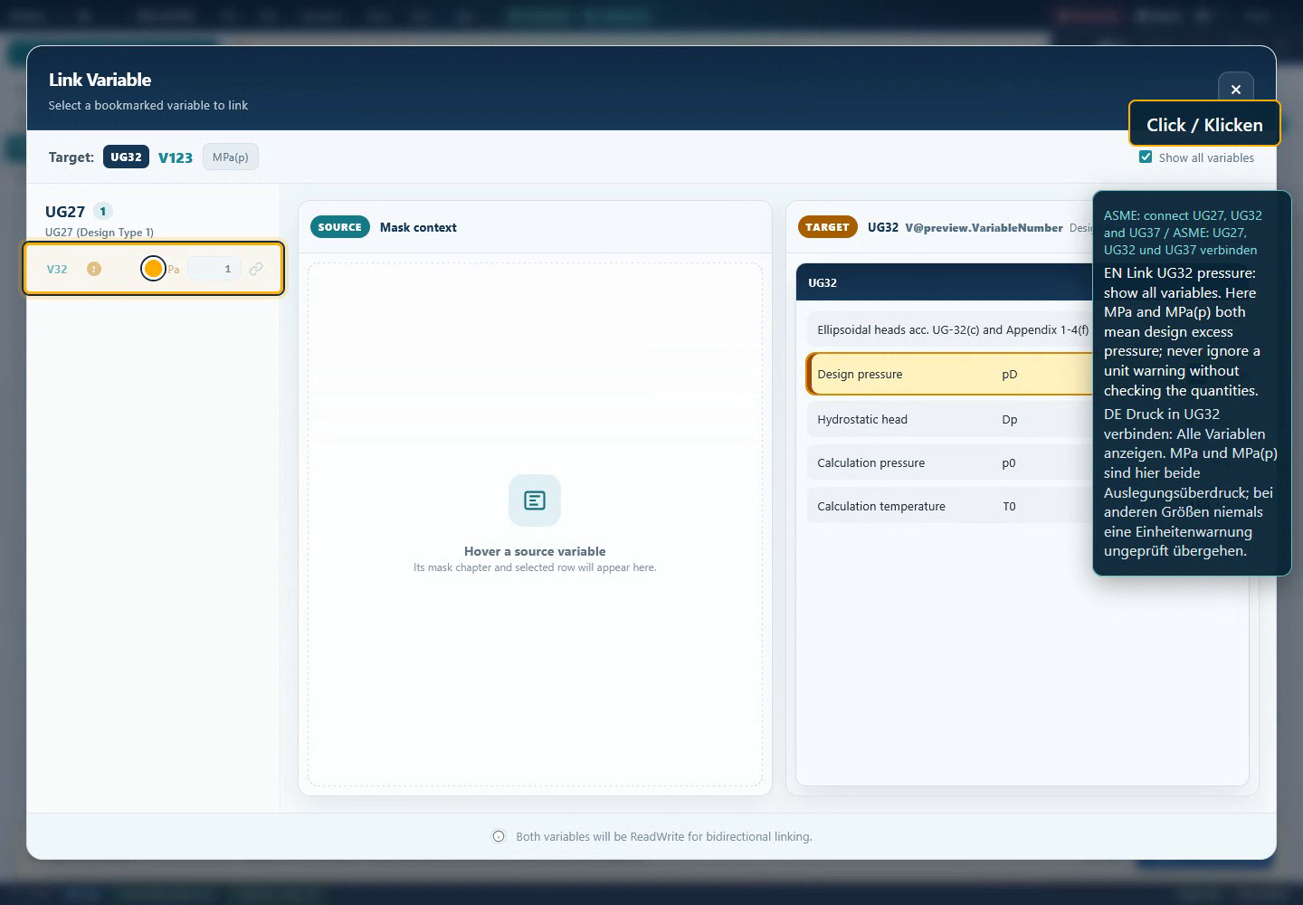
Checking source, target and units in the common dialog
This approved historical capture comes from the ASME tutorial and shows UG27/UG32. It explains the common software operation. Visible module identifiers, figures and units belong to the ASME case; they are not relabelled as Eurocode inputs. Use the mapping above for your shell project.
 123
123- 1. The bookmarked source belongs to a specific chapter. Check which geometric surface or action it actually describes.
- 2. The target shows identifier and unit. Metres and millimetres, radius and diameter, or characteristic and factored loads must not be equated because numbers look similar.
- 3. The dialog describes a bidirectional ReadWrite relationship. The preferred editing location in the data plan therefore does not enforce one-way propagation. Check observed updates in your own copy.
Chapter 17Calculation completion, individual resistance and overall assessment
Assess results in three steps. First: are inputs, units, construction and states complete and consistent? Second: which individual engineering conditions are satisfied? Third: do those conditions collectively cover the required structure and load-case task? Successful calculation completion does not automatically answer the second or third question.
The roof specification illustrates this separation: its pressure comparison is favourable, its equivalent-stress condition is not. In the ring specification, elementary flat-bar properties agree while imperfection conditions are unsatisfied. In the authored cylinder case, 10 mm wall satisfies the isolated axial comparison and 8 mm does not. Preserve these distinct statements explicitly.
Maintain a result row for every course or component, recording load case, applied quantity, resistance, utilisation and applicability/geometry conditions. Also identify any required interaction between stress components. A favourable axial state can have a different governing condition under simultaneous circumferential compression or shear.
Variant comparisons should also check quantities expected to remain unchanged. Another wall value can change midsurface radius, area, buckling parameters and self-weight; changing only a resistance factor should not redefine characteristic material strength. These dependencies help distinguish operating discrepancies from expected engineering effects.
A traceable report contains code/source edition, material and fabrication assumptions, loading concept, result conditions, connected components and remaining tasks. The EC3A deployment gap, unexecuted software links and missing project-specific seismic parameters remain visible. A complete package handbook explains these relationships without representing open project assessments as finished.
Back to top ↑Chapter 18Saving traceable projects and variants
Name chapters by component and case, such as “C1 – cylinder – axial compression”, “R1 – ring – external pressure” or “E1 – seismic – site assumptions”. Also record actual module identifier and construction. This preserves the relationship between display names such as EC3Cyl and identifiers such as EC3C.
Save your own state before a substantial revision. Documentation should include inputs with units, material selection, fixed/free quantities, load-factor status, links and result conditions. This book's learning sheet contains a clearly restricted analytical task; it is not a substitute for a complete saved SOL project.
For checking, open a project you created in a new session of your own. Compare chapter count, constructions, geometry, units, materials, loads and result groups. In a copy, change an actually linked quantity to check that its connection persisted. A successful download alone proves neither restoration of state nor correct subsequent calculation.
No such Eurocode roundtrip was newly executed for this edition. Verified static book functions cover local reading, search, language, printing and learning-data download. Distinguish these documentation checks from the separate project and engine checks still required.
Back to top ↑Chapter 19Resolving errors and discrepancies systematically
Work in your own copy and change one cause at a time. Record expected response, actual input and specific result condition. These situations address the package's main engineering and numerical distinctions.
Does this cover the entire Eurocode family?
The configured software package contains seven entries for shells/silos and seismic actions. It is not a complete collection of every Eurocode part for every structure or material. The package map identifies actual scope.
The module says 2017 but the catalogue says 2026.
EC3C/EC3S metadata identify 2017-07. DIN Media lists 2026-08 as successor. This handbook explains the inspected older source basis. Separately check the required project edition and its implementation in your program version.
Where can I find EC3A?
It appears in package configuration but has no inspected standalone Web registration. All-Dev contains support/junction-ring source constants; its label XML is empty. This does not justify inventing an available menu command.
Are EC3C and EC3Cyl different modules?
EC3C is the configured identifier and EC3Cyl its display name. EC3S/EC3Stiff, EC3T/EC3Cone and EC3D/EC3Roof correspond similarly. This mapping is limited to those inspected metadata.
Why is teaching outside diameter 2010 mm?
With 10 mm wall it gives midsurface radius 1000 mm. The source derives mean diameter from outside dimension minus wall. A 2000 mm outside diameter would therefore be a different case.
Why does radius increase when wall gets thinner?
Outside dimension stays fixed in the study. Reducing wall from 10 to 8 mm moves midsurface radius from 1000 to 1001 mm. Constant midsurface radius would be a different geometric constraint.
Buckling stress 1270.5 MPa exceeds yield strength.
That is ideal elastic buckling stress. Imperfection and buckling reductions plus the resistance factor lead to the design resistance considered here. Do not compare applied stress directly with the ideal value.
Wall decreases by 20%, but utilisation rises more.
Section area decreases, increasing stress. Buckling resistance changes at the same time. Their combined effect gives 0.897→1.185 in the teaching case; this is not simple proportional scaling.
Can I order the derived target wall 9.156315 mm?
It is the theoretical intersection of limited teaching relationships at utilisation one. Fabrication, wall definition, allowances and other checks are not automatically included. An orderable thickness must satisfy the actual overall task.
Can Q simply be increased?
It may be changed in an explicitly identified sensitivity study. A genuinely more favourable imperfection assumption needs an appropriate fabrication/measurement basis. Entry alone does not establish improved fabrication quality.
Does a ring stiffener replace shell buckling checks?
Ring action and shell panels must be assessed together. The ring has its own section, stability and imperfection conditions. A favourable flat-bar section does not establish every surrounding panel.
Ring area agrees, but a condition fails.
Area, effective combined section, lateral stability, out-of-roundness and initial twist are different questions. In the archived ring specification, simple section properties are traceable while V45/V51 are expected unsatisfied. Read the actual condition.
The roof has enough pressure reserve: is it adequate?
Stress comparison and geometry conditions remain separate. In the archived roof case, 0.1 MPa is below the considered resistance but 1500 N/mm² exceeds the stress limit 220 N/mm². One comparison is insufficient.
What does expectSuccess=true mean in a test?
It is a stored expectation concerning test/calculation completion. The same file can contain unsatisfied engineering conditions as expected results. Its content also does not prove a test executed today.
Can I link roof angle and hopper angle?
Definitions differ: EC3D identifies inclination to horizontal, EC3T half-apex angle. Check actual geometry and derive the appropriate relation; similar labels do not guarantee equality.
Transferred radius becomes a thousand times too large.
EC3C V46 and EC3S V13 use metres and millimetres respectively in the inspected source definitions. Also distinguish radius from diameter. Check meaning and scale before connecting.
Does the wind force still need a factor?
EC3C V83/V84 explicitly identify inclusion of a safety factor. The source of an external load must establish whether it is already factored. Unnoticed double factoring changes the comparison.
Why do BEB and 1998 differ?
They are separate procedures with their own model, period and distribution quantities. BEB also distinguishes Eurocode 8 and DIN 4149 variants. Compare assumptions and load conventions before expecting identical results.
Can I enter kilograms directly as weight force?
Mass is not force. The 1998 source identifies V68 onward as weight forces. Check visible unit and the convention required by the spectral calculation, including treatment of gravitational acceleration.
Which runtime evidence does this book provide?
Eurocode figures are independent source arithmetic and selected archived test expectations. There is no new Eurocode overall execution. The genuine ASME context capture explains only common link operation; book QA checks content and static functions.
Chapter 20Terminology in the structural workflow
| Term | Meaning |
|---|---|
| Action | Loading on the structure; identify characteristic or factored status. |
| Design resistance | Resistance used in comparison after associated reductions and factors. |
| Ideal buckling stress | Elastic reference quantity, not directly allowable stress. |
| Imperfection | Geometric deviation or deviation form/amplitude adopted in the model. |
| Shell midsurface | Geometric reference midway through the wall adopted. |
| Meridional force | Force in the meridional direction; distinguish total force from force per circumferential length. |
| Interaction | Combined assessment of simultaneously acting stress components. |
| Procedure applicability | Conditions permitting use of a selected simplified procedure. |
| Test expectation | Stored target value; not equivalent to an observed current execution. |
Chapter 21Mapping fields reliably
These 114 selected fields explain geometry, loading and results. They do not reproduce every internal helper variable. Units are specified where a source relationship or evaluated example establishes the reference. In your actual mask, check visible unit, construction and input/result state. Historical raw labels are explained editorially and provided in both languages.
1998 / EC8
| Field | Working meaning |
|---|---|
1998:V3 | Ground class |
1998:V5 | Subsoil class |
1998:V6 | Importance category |
1998:V14 | Natural period |
1998:V20 | Damping correction |
1998:V21 | Viscous damping ratio |
1998:V24 | Importance factor |
1998:V50 | Horizontal design spectrum |
1998:V56 | Storey count |
1998:V59 | Height of weight 1 above reference plane |
1998:V68 | Weight force 1; not mass in kg |
1998:V86 | Horizontal storey force 1 |
1998:V96 | Horizontal base force |
1998:V97 | Base moment |
EC3C / EC3Cyl
| Field | Working meaning |
|---|---|
EC3C:V5 | Number of courses, top down |
EC3C:V6 | Outside diameter; source m |
EC3C:V7 | Course 1 wall; mm |
EC3C:V8 | Course 1 length; source reference mm |
EC3C:V21 | Total shell length |
EC3C:V31 | Shell material |
EC3C:V32 | Metal temperature |
EC3C:V33 | Elastic modulus E |
EC3C:V34 | Characteristic yield strength fy |
EC3C:V41 | Mean diameter; source m |
EC3C:V46 | Midsurface radius; source m |
EC3C:V47 | Mean shell thickness |
EC3C:V83 | Horizontal wind action including factor |
EC3C:V84 | Wind overturning moment including factor |
EC3C:V94 | Operating excess pressure including factor |
EC3C:V95 | Operating external-pressure differential including factor |
EC3C:V181 | Axial length parameter, course 1 |
EC3C:V185 | Axial buckling coefficient Cx, course 1 |
EC3C:V191 | Fabrication-quality selection |
EC3C:V192 | Fabrication-quality parameter Q |
EC3C:V193 | Characteristic imperfection amplitude |
EC3C:V197 | Elastic imperfection factor before corrections |
EC3C:V207 | Relative shell slenderness |
EC3C:V219 | Governing elastic imperfection factor |
EC3C:V243 | Buckling reduction χ, course 1 |
EC3C:V247 | Ideal meridional buckling stress |
EC3C:V255 | Characteristic buckling stress |
EC3C:V259 | Design buckling stress |
EC3C:V263 | Axial buckling condition, course 1 |
EC3C:V313 | Value of axial buckling comparison, course 1 |
EC3S / EC3Stiff
| Field | Working meaning |
|---|---|
EC3S:V4 | Ring stiffener function |
EC3S:V6 | Shell outside diameter; source m |
EC3S:V7 | Shell wall; mm |
EC3S:V8 | Length of ring-stiffened cylinder |
EC3S:V9 | Spacing of light rings |
EC3S:V11 | Number of light rings |
EC3S:V13 | Shell midsurface radius; source mm |
EC3S:V18 | Buckling reduction of panel between rings |
EC3S:V20 | Section shape |
EC3S:V25 | Flat-ring placement |
EC3S:V31 | Flat-bar width; mm |
EC3S:V32 | Flat-bar thickness; mm |
EC3S:V45 | Radial out-of-roundness condition |
EC3S:V49 | Actual initial twist |
EC3S:V51 | Initial-twist condition |
EC3S:V55 | Ring area; mm² in flat-bar example |
EC3S:V56 | Second moment of area y |
EC3S:V57 | Second moment of area z |
EC3S:V60 | Effective shell width for normal force |
EC3S:V66 | Effective ring-section area |
EC3S:V167 | Shell metal temperature |
EC3S:V168 | Axial load including safety factor |
EC3S:V169 | Constant external pressure including factor |
EC3S:V171 | Ring metal temperature |
EC3S:V180 | Ring flexural-buckling resistance factor |
EC3T / EC3Cone
| Field | Working meaning |
|---|---|
EC3T:V7 | Local design meridional force per length |
EC3T:V8 | Asymmetry factor |
EC3T:V11 | Local wall thickness |
EC3T:V13 | Tensile strength |
EC3T:V15 | Design meridional membrane resistance |
EC3T:V17 | Half-apex angle |
EC3T:V18 | Radius at considered mechanism |
EC3T:V19 | Wall-friction coefficient |
EC3T:V20 | Yield strength |
EC3T:V25 | Effective radial force at junction |
EC3T:V26 | Effective junction moment |
EC3T:V32 | Hopper wall at junction |
EC3T:V33 | Cylinder wall at junction |
EC3D / EC3Roof
| Field | Working meaning |
|---|---|
EC3D:V4 | Surface equivalent-stress condition |
EC3D:V5 | Calculated surface equivalent stress |
EC3D:V6 | Yield strength |
EC3D:V7 | Resistance factor γM0 |
EC3D:V8 | Ideal buckling external pressure |
EC3D:V10 | Elastic modulus |
EC3D:V11 | Roof outside radius; mm in test |
EC3D:V12 | Minimum wall thickness |
EC3D:V13 | Inclination to horizontal |
EC3D:V14 | Design buckling resistance |
EC3D:V15 | Resistance factor γM1 |
EC3D:V16 | Reduction coefficient αp |
EC3D:V17 | Maximum local design external pressure |
EC3D:V18 | Pressure comparison |
EC3D:V21 | Roof outside diameter |
BEB / Beben
| Field | Working meaning |
|---|---|
BEB:V4 | Equivalent-cantilever outside diameter |
BEB:V5 | Equivalent-cantilever wall |
BEB:V11 | Equivalent-cantilever elastic modulus |
BEB:V27 | Selected period |
BEB:V28 | Period method |
BEB:V29 | Simplified-procedure applicability |
BEB:V32 | Design spectrum |
BEB:V33 | Correction factor |
BEB:V34 | Total force |
EC3A / EC3A
Meanings from commented source constants only; no available Web mask claimed.
| Field | Working meaning |
|---|---|
EC3A:V4 | Support type; source constant only |
EC3A:V5 | Ring shape; source constant only |
EC3A:V6 | Shell outside diameter |
EC3A:V7 | Shell wall |
EC3A:V10 | Hopper wall |
EC3A:V11 | Support-skirt wall |
EC3A:V12 | Plate-ring thickness |
EC3A:V13 | Radial plate-ring width |
Chapter 22Sources and limits of the evidence
This edition of 7 September 2026 uses Web sources (main13.0, 1cd12e8b173ba72aa5c95c98a14772b7ee537997) and All-Dev (fix-iteration/v10, 40606b705b2df95e550ffef5e98ab733ccc66229). The source snapshot contains all seven package members, nine available masks including four BEB variants, labels and file hashes. Commented constants were frozen for EC3A because its label XML is empty and no Web registration exists. The overall modified Web tree belongs to the handbook campaign; specifically inspected source paths had no reported local changes.
Review particularly covered EC3C midsurface geometry, length range, axial buckling stress, imperfection factor, slenderness, buckling reduction and resistance branches. The core case deliberately excludes additional stresses and internal-pressure corrections. EC3S sources confirm differing radius scales and flat-bar geometry; EC3D sources support roof arithmetic and separate result conditions. This does not comprehensively review full code texts or every remaining calculation branch.
The evidence list records four specifications for 1998, EC3S, EC3T and EC3D with hashes and fixture dates. Their expected values are not newly observed runtime outputs. Ring and roof cases explicitly include unsatisfied engineering conditions. The existing editorial EC3C worked solution is used only for independently checked selected steps.
Six original symbols and an approved ASME context capture are available locally with provenance and SHA-256. The frame comes from the ASME video of 6 September 2026 at 80 s and explains only the common link dialog. Its exact loaded binary revision is not independently identified. Markings are separate HTML elements; original names, warnings and pixels remain intact.
The Eurocode book's runtime level remains source-only. Not newly executed: complete Eurocode starts, a connected overall case, actual inverse solver operation, valid project-specific seismic/ring/hopper/roof/support assessments, save/reopen and Desktop/Web parity. Separate book verification checks content, source identities and static usability. A later owned execution can follow the data plan and address those gaps directly.
Back to top ↑