FEA Toolbox – Finite element calculations
Select models, prepare loads and geometry, and review FE results traceably.
No chapter found. Try another search term.
Chapter 01What the FEA Toolbox helps you solve
The finite element method describes how a component deforms under loading and what stresses develop. It is especially useful when the actual geometry, a nozzle, a support or a load combination is not adequately represented by a simple design formula. A coloured stress plot alone does not establish that pressure equipment is adequate for its intended service. That conclusion also requires a suitable model, the correct load cases and an assessment consistent with the governing code.
This handbook takes you through selecting a calculation route, preparing a nozzle model, independent checks and reviewing a result report. The configured package contains exactly one legacy module: FEM, with registered masks for cylindrical shells and torispherical heads. The current “FEA Toolbox” product page and the FELV/COMSOL workflow are additional, separately explained entry points. They are not further package members automatically equivalent to FEM.
The program captures in this edition show the genuinely built product selection. Calculation examples are expressly analytical checks and prepared modelling procedures. No new FEM or COMSOL calculation was performed for this handbook. You can reproduce the working method and review steps without confusing values from another calculation route with an observed FE result.
Back to top ↑Chapter 02Distinguishing FEM, Toolbox Design, Toolbox Pro and FELV
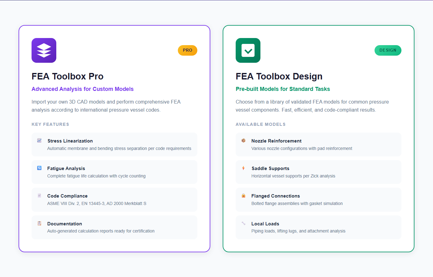
Start by identifying the model you intend to work on. For a predefined standard geometry, the product page offers a model selection under “FEA Toolbox Design”. For your own CAD geometry, it describes “FEA Toolbox Pro”. The page states their intended uses; the installed product version, available functions and its accompanying instructions determine the actual operation. A description such as “Code Compliance” does not replace selection and review of an appropriate assessment route.
The legacy FEM module has its own geometry, material, load and control fields. Its sources contain a COM connection and older ANSYS branches. The program text itself refers users of the former ANSYS calculations to FELV with its COMSOL interface. An old mask therefore does not establish that every branch can run in your Web session. Check the offered design variant and documented calculation route of your installation.
FELV is a separate module in the EN 13445 environment. Its Web interface offers “Run as COMSOL Job”, “Connect COMSOL-App” and a job inbox. A background job and an interactive coupling follow different state sequences. Use the appropriate procedure in the COMSOL chapter. Do not transfer FEM field identifiers to FELV without checking their meaning.
 12
12- Pro describes the route for custom CAD models. Actual functionality belongs to the particular product version.
- Design describes predefined model families. The description is not calculation acceptance.
Real client, 7 September 2026; isolated preview, no FE solver run. Original English UI text is unchanged. Open original
Chapter 03Opening the Toolbox and selecting a model
- Open the FEA Toolbox from “Apps”. Its separate page is available at FEA Toolbox.
- Read the Pro and Design descriptions. For a predefined model, choose “Select Model” in the “Download & Install” section.
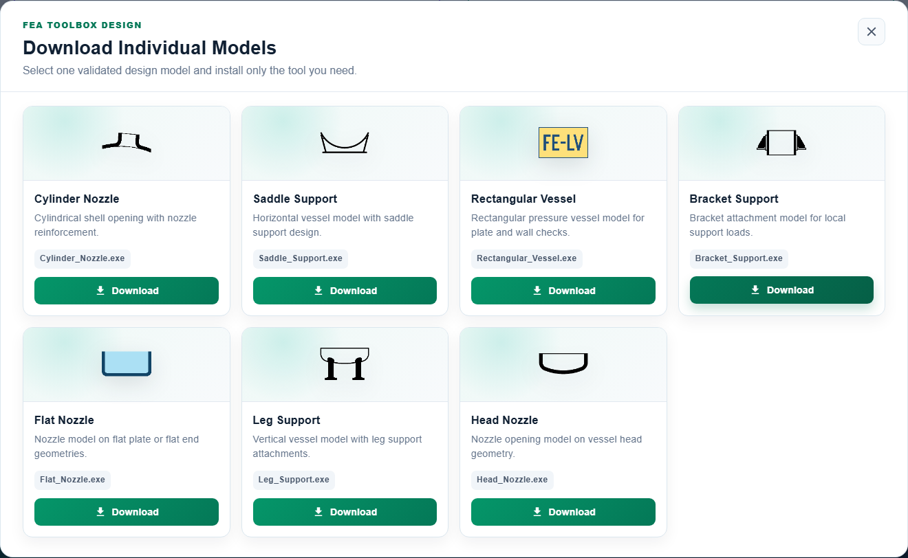
- Compare the model name with your task. “Cylinder Nozzle” represents a nozzle in a cylindrical shell; “Head Nozzle” represents a nozzle in a vessel head. The pictures help select models and are not result plots.
- Record the offered product, version and filename. Follow that product’s instructions for download and startup. Opening the selection does not start an FE calculation.
- For cloud use, “Launch Cloud Service” opens the portal. A maintenance message or missing access is an access issue; changing geometry values will not resolve it.
The following original capture was made on 7 September 2026 in an isolated preview of the real client. With the download catalogue unavailable, the application displays its seven built-in fallback model cards. In operation, the managed catalogue may supply other versions or models. The capture verifies the selection interface, not installation or successful calculation of every displayed product.
 12
12- Cylinder Nozzle: model family for a nozzle in a cylindrical shell.
- Head Nozzle: separate selection for a nozzle in a vessel head. Filenames and model families remain distinct.
Real client, 7 September 2026; isolated preview, no FE solver run. Original English UI text is unchanged. Open original
Chapter 04Using the seven model families deliberately
Let geometry and load path determine your selection. A nozzle model does not become suitable for a bracket merely because both produce local stresses. Nozzles depend on the opening, connected wall and possible reinforcement; supports additionally depend on contact areas, load introduction and vessel deformation. Flat walls and their connections in a rectangular vessel behave differently from a cylindrical shell.
| Model | Filename | Selection guidance |
|---|---|---|
| Cylinder Nozzle | Cylinder_Nozzle.exe | Nozzle in a cylindrical shell; pressure and local connection loads. |
| Saddle Support | Saddle_Support.exe | Horizontal vessel on saddles; support and load distribution. |
| Rectangular Vessel | Rectangular_Vessel.exe | Rectangular vessel; flat walls and their connections. |
| Bracket Support | Bracket_Support.exe | Bracket attachment; local load introduction into the vessel. |
| Flat Nozzle | Flat_Nozzle.exe | Nozzle on a flat plate or flat end. |
| Leg Support | Leg_Support.exe | Vertical vessel on legs; attachment and support loads. |
| Head Nozzle | Head_Nozzle.exe | Nozzle in a dished head; curved connection geometry. |
This table represents the seven built-in selection cards. It is not a complete list of every product function or a new licensing entitlement. A standard model still requires comparison of its geometric limits, boundary conditions and available load cases with your construction. If a weld, support or asymmetry lies outside that model description, determine the appropriate extension or a move to a custom model before using a numerically convenient field.
Back to top ↑Chapter 05Preparing geometry and effective wall thicknesses
Prepare a dimensioned sketch with explicit inside or outside references before entering values. In legacy FEM, V6 denotes the body outside diameter and V5 the nozzle outside diameter. V8 and V7 are their wall thicknesses. A nominal pipe size is not a substitute for either diameter. For a cylindrical body with Do = 1020 mm and actual thickness 12 mm, the initial inside diameter is 996 mm.
The inspected transfer to the older FE object uses effective body thickness V8 − V41 − V42 and nozzle thickness V7 − V45 − V46. Thus 12 − 1 − 1 mm leaves 10 mm. V41 and V42 are allowances, not load-application switches. At this point the old variable comments no longer agree with naming and actual transfer. Check how the selected model route treats the corresponding inside/outside reference of reduced geometry; effective thickness alone does not establish a displacement of the model surfaces.
V10 depends on the design variant: cylinder length in FEM-1, straight-flange height for a head. V13 is an additional crown diameter in applicable variants, not a universal replacement for V6. Set inclination and offset from the sketch as well. After every geometry change, inspect the newly generated model before assessing an existing stress plot.
Back to top ↑Chapter 06Assigning materials, temperature and stiffness
Body, nozzle and reinforcement have separate material assignments: V2, V3 and V4 in legacy FEM. Matching material names do not guarantee identical temperature-dependent properties if delivery condition, product form or source differs. Record calculation temperature V1 and the material basis alongside the model variant.
Allowable stresses V21–V23 and elastic moduli V24–V26 perform different roles. The elastic modulus governs elastic stiffness; allowable stress belongs to subsequent assessment. Changing a limit does not make the model stiffer. Poisson ratios V27–V29 are dimensionless. The unit N/mm² in an old variable comment is incorrect for these three fields and is deliberately not repeated here.
For a first linear check, use an explicitly documented educational elastic material, for example E = 200000 N/mm² and ν = 0.3. These are teaching inputs, not an approved material dataset. A real assessment requires suitable temperature-dependent properties and a defined design basis. Contact, plasticity and temperature-dependent expansion introduce additional model properties that E and ν alone do not describe.
Back to top ↑Chapter 07Applying pressure, forces and moments unambiguously
Before calculating, establish whether pressure means internal gauge pressure, external pressure or a difference between two operating states. Legacy FEM field V30 is described as internal gauge pressure in N/mm². 20 bar = 2 N/mm² = 2 MPa. Entering 20 in a field based on N/mm² would apply ten times the intended pressure. Adjacent thermodynamic modules may require absolute pressure instead; do not connect those values merely because both are named “pressure”.
Nozzle forces V31–V33 are described in N and moments V34–V36 in Nmm. One kNm equals 1000000 Nmm. Record a right-handed coordinate system, positive directions and the application point. Transferring a force from the nozzle end to the axis intersection introduces an additional moment from its lever arm. Sign convention and reference point must therefore be transferred together.
Investigate pressure alone first, then individual force or moment components, and finally a justified combination. Stress tensors can be superposed for an unchanged linear model. The largest von Mises values from different individual plots cannot simply be added. When contact changes, plasticity or large deformations matter, linear superposition is generally not the appropriate calculation route.
Back to top ↑Chapter 08Checking boundary conditions and load path
A component needs enough constraints to remove indeterminate rigid-body motion. More constraints are not automatically better: fully fixing a cut edge can suppress natural radial expansion or axial extension and introduce extra stresses. For each condition, describe the real component or symmetry it represents.
In legacy FEM, V37 and V38 concern longitudinal stress in the shell and nozzle, V39 concerns a rigid nozzle end, and V40 specifies load application. Check the available selection text. The transfer distinguishes nozzle end, cut plane and axis intersection, among other options. Switches and load components must describe the same mechanical situation; a flange boundary is not rigid merely because a flange is present.
For a closed pressure vessel, the axial force caused by pressure on the end belongs in equilibrium. When modelling an isolated shell segment, replace that effect appropriately. Compare applied loads with resulting reactions, including their lever arms. An attractively symmetric deformation with an incorrect total force is not a plausible check. In symmetry models, also establish whether each force describes the complete vessel or only the modelled fraction.
Back to top ↑Chapter 09Teaching case: preparing a nozzle on a cylindrical shell
The following case fully describes the model-preparation task, but is not an already calculated FEM project. It separates measured geometry from effective calculation geometry. Use it in your available model route and document that route’s additional required fields, mesh definition and constraints. No SOL file is supplied that would falsely suggest an executed solver run.
| Quantity | Teaching input | Mapping / meaning |
|---|---|---|
| Body outside | 1020 mm | FEM V6 |
| Body thickness | 12 mm | FEM V8 |
| Body allowances | 1 mm + 1 mm | FEM V41 + V42 |
| Cylinder length | 2000 mm | FEM-1 V10 |
| Nozzle outside | 114.3 mm | FEM V5 |
| Nozzle thickness | 8 mm | FEM V7 |
| Nozzle allowances | 0.5 mm + 0.5 mm | FEM V45 + V46 |
| Nozzle length | 150 mm | FEM V9 |
| Offset / inclination | 0 mm / 0° | Central radial nozzle |
| Internal gauge pressure | 2 N/mm² | FEM V30 |
| Nozzle forces / moments | 0 N / 0 Nmm | FEM V31–V36 |
| E / ν | 200000 N/mm² / 0.3 | Elastic teaching material; no material approval |
- Select the cylinder-nozzle variant and enter outside dimensions and wall thicknesses with units.
- Set allowances separately: effective body thickness is 12 − 1 − 1 = 10 mm; nozzle thickness is 8 − 0.5 − 0.5 = 7 mm. Inspect the actually generated surfaces and remaining material.
- Assign the teaching material to all bodies considered. Activate reinforcement only when its specific geometry forms part of the chosen model.
- Apply internal gauge pressure alone first. External nozzle forces and moments are zero in the base case.
- Define axial pressure closure, suitable cut conditions and a traceable mesh sequence. Generate the model and inspect its geometry.
- Execute the available solver. Save messages, reactions, deformation, stress distributions and the exact model state.
- Compare the undisturbed shell region with the analytical check below. Assess the local nozzle region separately.
Chapter 10Calculating an independent cylinder check
The check expressly uses an undisturbed closed elastic cylinder with inside radius a = 500 mm, outside radius b = 510 mm and zero external pressure. These radii define the check geometry themselves; they do not claim how a particular FEM variant removes allowances geometrically. The solution applies away from ends, nozzles and other local disturbances.
With A = p a²/(b² − a²) and B = p a²b²/(b² − a²), shell stresses are σr(r) = A − B/r² and σθ(r) = A + B/r². Force equilibrium at the closed end gives σz = A. Check boundary conditions first: σr = −p inside and σr = 0 outside. Axial stress multiplied by the metal cross-sectional area equals pressure force on the internal end area.
| Pressure [MPa] | σθ inside [MPa] | σθ outside [MPa] | σz [MPa] | σr inside / outside [MPa] |
|---|---|---|---|---|
| 2 | 101.0099 | 99.0099 | 49.5050 | -2.0 / 0.0 |
| 3 | 151.5149 | 148.5149 | 74.2574 | -3.0 / 0.0 |
The table was calculated directly from these equations and checked for boundary conditions and equilibrium. It contains no observed FEM results. At 2 MPa, inside hoop stress is approximately 101.01 MPa and axial stress approximately 49.50 MPa. A thin-wall estimate using mean radius 505 mm gives 101 MPa hoop and 50.5 MPa axial stress; the approximation explains the small difference. Compare matching stress components at matching locations before interpreting a discrepancy as a software error.
Back to top ↑Chapter 11Investigating a load change and inverse calculation
Copy the base case and increase internal pressure alone from 2 to 3 MPa. Stresses in the unchanged linear-elastic cylinder increase by a factor of 1.5. The analytical table includes this variant. An FE model with the same geometry and linear constraints should show the same scaling. If contact state or stiffness changes simultaneously, simple scaling is no longer the appropriate expectation.
For a targeted inverse calculation, prescribe an analytical comparison quantity. To obtain 80 MPa inside hoop stress in the undisturbed check cylinder, p = 80 × (b² − a²)/(a² + b²), approximately 1.584 MPa. This is a mathematical target calculation, not allowable operating pressure according to ASME, AD 2000 or EN. It excludes local nozzle stress, further loads and the required assessment criteria.
Transfer such a target only as a new input pressure in a model copy. Then inspect the newly calculated result and remaining assessments. Do not change a displayed maximum-stress output into an input unless the actual application offers a suitable inverse route. The inverse study is complete when its defined target and the remaining requirements have been assessed using a consistent new state.
Back to top ↑Chapter 12Checking mesh refinement against a fixed evaluation target
Before refinement, define the quantity that should stabilize: displacement at a fixed point, a reaction force, membrane stress on a named section, or a stress quantity at a defined distance from a notch. Record element type, order, local sizes, elements through the thickness and evaluation position. Total element count alone does not sufficiently describe the quality of a local nozzle mesh.
Calculate a traceable sequence of coarser and finer meshes while retaining geometry, load and evaluation. Record mesh identifier, degrees of freedom, target quantity, relative change and calculation messages. Relative change can be expressed as |new − old|/|new| when the new value is nonzero. Establish the tolerance required for your task through engineering judgement; this handbook does not assert a universal percentage threshold.
Legacy FEM fields V17–V19 control calculation circles and support points in that particular model generator. They are not a general equivalent of every COMSOL mesh setting. Document the generated mesh itself. The COMSOL explanation of meshing linear models helps distinguish element display from element order; it does not establish a particular mesh setting for your Toolbox version.
Back to top ↑Chapter 13Reading stress plots and linearization correctly
Before reading a number, read the plotted quantity, its unit, load case and selected region. Hoop stress, principal stress, von Mises equivalent stress and Tresca stress intensity are different quantities. Unaveraged element values and averaged nodal values can differ as well. A comparison is meaningful only when these details match.
Stress linearization separates the through-wall distribution of stress components into membrane and bending parts; the remaining local deviation forms the peak part. Linearization preserves the corresponding force and moment effects. The COMSOL introduction explains this method, while the result documentation describes output names. This methodological information does not replace classification of stresses under the selected code.
A simple check distribution across a 10 mm wall is σ(z) = 100 + 4z MPa for −5 ≤ z ≤ 5 mm. Membrane stress is 100 MPa, and surface bending contributions are −20 and +20 MPa. This is an analytical teaching profile, not a nozzle result. In a real model, define the section, orientation and endpoints traceably. An automatic line in an unsuitable location can give mathematically correct but physically inappropriate values.
Back to top ↑Chapter 14Interpreting local peaks, contact and stability
If a local stress peak continues increasing with every mesh refinement, investigate the model at that location. A sharp re-entrant corner, point load or abrupt change in constraints can produce a singularity. An ever-higher peak is then not a meaningfully converged component result. A real notch effect must not simply be hidden either. Determine whether geometric resolution, load distribution or the assessment-specific evaluation method needs adjustment. The COMSOL explanation of singularities describes this distinction.
In contact models, open and closed contact areas form part of the result. Review contact state together with force equilibrium and deformation. Higher friction or an artificially rigid connection is not a general remedy for a difficult calculation. First establish the real connection being represented and whether its conditions are fully specified.
External pressure and compressive forces may require a stability assessment. A linear-elastic stress plot does not automatically answer the buckling question. Likewise, an individual eigenvalue without appropriate interpretation is not a generally permissible load factor. Required imperfections, nonlinearities and criteria depend on the actual assessment. Reference that separate calculation route in the report instead of inferring adequacy from an unremarkable stress colour.
Back to top ↑Chapter 15Using COMSOL jobs and interactive coupling
This sequence belongs to the existing FELV Web integration. It does not state that legacy FEM has the same buttons. Open the actual FELV instance and inspect its inputs, material assignment and variant. “Connect COMSOL-App” pairs an interactive application with a session; “Run as COMSOL Job” submits a snapshot to a background workflow. Deliberately choose the route intended for your task.
- Save the reviewed input state and start the job from the correct instance.
- Check the offered documentation and language choices in the start dialogue. Record the job identifier.
- Open “COMSOL Jobs” to find status and subsequently available results. “Queued” does not mean “calculated”.
- After completion, first read status, messages and the report. A completed technical process does not establish a passed engineering assessment.
- Use “Load results” only for the corresponding project state. If current inputs differ, the implementation presents a conflict decision; compare states before forcing a result application.
The inspected implementation archives an input snapshot and collects results and diagnostics in an inbox. Availability and retention depend on the environment. Demo access in particular has its own restrictions. This handbook checked the workflow against the current implementation but did not execute a newly started COMSOL job. An older architecture proposal is therefore not the basis for any claimed new runtime results.
Back to top ↑Chapter 16Working with vessel and piping calculations
Use the AD 2000, EN 13445 and ASME handbooks to understand preliminary component design. A calculated required thickness is not automatically the actual thickness in the FE model. Transfer the selected construction, allowance state, temperature case and material basis as one coherent dataset.
For every transfer, prepare a small mapping table: source module and field, physical meaning, unit, destination model and geometric reference. For example, an outside diameter belongs only in a destination field using the same outside reference. Pressure needs a check for absolute or gauge basis. Nozzle loads additionally need coordinates and an application point. A technical connection between numerical fields does not replace this meaning check.
In a connected project, record which module owns each prescribed quantity. Change the common input at that source and then check every dependent calculation. No newly verified automatic chapter connection is claimed for the FEM/Toolbox combination described here. If your actual model route offers no such transfer, perform the documented mapping manually and retain both states.
Back to top ↑Chapter 17Saving models, reopening them and reviewing results
Retain geometry, application version, load-case table, material basis, constraints, mesh definition and the complete result report alongside the project. For custom CAD models, retain the imported source file as well. A screenshot showing maximum stress is insufficient to reconstruct a model later. Use distinct names for base, pressure and geometry variants.
Reopen a copy and compare central inputs before recalculating. Check dimensions, units, allowances, load application, design variant and material properties. Then establish that model, mesh and results actually belong to that state. For a background job, also compare the input snapshot with the current session. Successful file opening and a successfully repeated solver calculation are separate checks.
For engineering release, the report must identify the criteria assessed and those outside the model. Record at least equilibrium, an independent check, mesh sensitivity, evaluated stress quantities and governing load cases. Explicitly identify fatigue, stability or contact questions not calculated within the associated assessment scope. The reopening sequence here is a reproducible review instruction; this edition did not execute a fresh FEM save/reload run.
Back to top ↑Chapter 18Resolving typical situations
Begin diagnosis with the most recently changed quantity. Distinguish access, model generation, solver execution and engineering evaluation. Record the first meaningful message, model state and affected load case. The following answers lead to a checkable next step.
Product selection shows different models.
The managed download catalogue can replace built-in cards. Record the actual offered application and version.
FEM is listed but does not start calculating.
Check mask, variant and available runtime. The legacy COM/ANSYS connection is not automatically a Web solver.
Cloud access reports maintenance.
Check access later or use the supplied local application. The message says nothing about geometry.
Effective thickness is smaller than expected.
Check V8−V41−V42 or V7−V45−V46. Do not reduce an already reduced value by the same allowances again.
Length is wrong after switching variant.
V10 means cylinder length or straight-flange height depending on variant. Recheck every geometric reference.
Pressure is wrong by a factor of ten.
Compare bar with N/mm²: 10 bar = 1 N/mm². Check source unit together with stored numerical value.
Moment is far too small.
Distinguish kNm, Nm and Nmm. One kNm equals 1000000 Nmm.
The load acts in the wrong direction.
Check coordinates, positive axis, nozzle inclination and application point together.
Axial stress is missing in the pressure case.
Check pressure closure and longitudinal-stress options. An open tube differs from the closed check cylinder.
The solver reports a singular system.
Check rigid-body motion, missing connections and unconstrained contact bodies. Do not constrain extra surfaces without mechanical justification.
Maximum stress grows with every finer mesh.
Inspect the peak location for corners, point loads or constraints. Define an assessable quantity and the appropriate assessment route.
Deformation looks exaggerated.
Read the display factor and actual displacement values. Graphic scaling is not an actual geometry change.
A stiffer material does not change every stress.
In force-controlled linear problems, equilibrium stresses can stay constant while displacements decrease. Check loading and constraint types.
Older documentation gives V27 a stress unit.
Poisson ratio is dimensionless. Use the current field meaning and material data.
Linearization differs from the colour scale.
Check components, section, endpoints and equivalent-stress definition. Membrane/bending values and local maxima are different evaluations.
The job completed but the assessment failed.
Distinguish technical job status from engineering utilization. Read the report and governing criteria.
Load results reports changed inputs.
Compare job snapshot and current session. A forced application can associate results with a different input state.
The CAD model is missing after reopening.
Check the project’s source file and import state. Archive project and geometry together.
The analytical pressure target is being used as operating approval.
The target limits only the defined teaching quantity. Assess all real loads, local checks and code criteria separately.
Stress values exist but no stability conclusion.
Set up the stability assessment as a separate task where required. Low stress alone does not establish buckling resistance.
Chapter 19Key FEM fields with meaning and units
The following reference describes selected working fields from the older FEM masks. It is not a field list for Toolbox Pro, Design or FELV. Meanings were cross-checked against masks, names and actual data transfer. Variant-dependent fields are not always visible together. Use the offered text in your application for selections rather than memorized internal numerical codes.
| Field | Meaning | Unit / role | Operating note |
|---|---|---|---|
| V1 | Calculation temperature | °C | Common temperature case. |
| V2 | Body material | – | Check product form and data basis. |
| V3 | Nozzle material | – | Assign separately from the body. |
| V4 | Reinforcement material | – | For reinforcement actually modelled. |
| V5 | Nozzle outside diameter | mm | Neither nominal size nor inside diameter. |
| V6 | Body outside diameter | mm | Observe the variant’s geometric reference. |
| V7 | Nozzle wall thickness | mm | Keep allowances V45/V46 separate. |
| V8 | Body wall thickness | mm | Keep allowances V41/V42 separate. |
| V9 | Nozzle length | mm | Check load application and length reference together. |
| V10 | Cylinder length / straight-flange height | mm | Variant-dependent, not one universal dimension. |
| V11 | Reinforcement outside diameter | mm | For the chosen reinforcement geometry. |
| V12 | Reinforcement thickness | mm | Match the actual attachment design. |
| V13 | Crown diameter | mm | Variant-dependent; not always visible. |
| V14 | Nozzle offset | mm | Check reference to the body axis. |
| V15 | Nozzle inclination | ° | Observe sketch and sign. |
| V16 | Inclination direction | ° | Match orientation to load axes. |
| V17 | Calculation-circle spacing | mm | Parameter of this particular generator. |
| V18 | Number of calculation circles | – | Not a general COMSOL element count. |
| V19 | Points around the circle | – | Inspect the generated mesh afterwards. |
| V20 | Set-in nozzle | Auswahl / selection | Select attachment type for the variant. |
| V21 | Allowable body stress | N/mm² | Assessment quantity, not stiffness. |
| V22 | Allowable nozzle stress | N/mm² | Assessment quantity, not stiffness. |
| V23 | Allowable reinforcement stress | N/mm² | Assessment quantity, not stiffness. |
| V24 | Body elastic modulus | N/mm² | Temperature-dependent elastic stiffness. |
| V25 | Nozzle elastic modulus | N/mm² | Temperature-dependent elastic stiffness. |
| V26 | Reinforcement elastic modulus | N/mm² | Temperature-dependent elastic stiffness. |
| V27 | Body Poisson ratio | – | Dimensionless; old unit comment is incorrect. |
| V28 | Nozzle Poisson ratio | – | Dimensionless; old unit comment is incorrect. |
| V29 | Reinforcement Poisson ratio | – | Dimensionless; old unit comment is incorrect. |
| V30 | Internal gauge pressure | N/mm² | 20 bar equals 2 N/mm². |
| V31 | Nozzle force x | N | Record axis, sign and application point. |
| V32 | Nozzle force y | N | Record axis, sign and application point. |
| V33 | Nozzle force z | N | Record axis, sign and application point. |
| V34 | Nozzle moment about x | Nmm | 1 kNm = 1000000 Nmm. |
| V35 | Nozzle moment about y | Nmm | 1 kNm = 1000000 Nmm. |
| V36 | Nozzle moment about z | Nmm | 1 kNm = 1000000 Nmm. |
| V37 | Longitudinal shell stress | Auswahl / selection | Observe pressure closure and variant. |
| V38 | Longitudinal nozzle stress | Auswahl / selection | Match the load model. |
| V39 | Rigid nozzle end | Auswahl / selection | Justify actual attachment stiffness. |
| V40 | Load application | Auswahl / selection | Nozzle end, cut plane or axis intersection as offered. |
| V41 | Body thickness allowance | mm | Subtracted from V8 in the inspected transfer. |
| V42 | Body corrosion allowance | mm | Also subtracted from V8. |
| V45 | Nozzle thickness allowance | mm | Subtracted from V7 in the inspected transfer. |
| V46 | Nozzle corrosion allowance | mm | Also subtracted from V7. |
| V67 | Model generation | Steuerung / control | Use automatic mode only in a supported runtime. |
| V68 | Calculation | Steuerung / control | Check model state before a new run. |
| V254 | Pause calculation | Steuerung / control | Label in the existing mask. |
| V255 | Create model | Steuerung / control | Model generation is not result assessment. |
| V256 | Calculate | Steuerung / control | Observe messages and actual completion. |
Pay particular attention to the different length references of V10, dimensionless V27–V29, and allowances V41/V42 and V45/V46. Generation and calculation control fields are not geometric results. The full mask inventory is retained in the source record; a long list of internal state fields would not replace an operating procedure.
Back to top ↑Chapter 20Sources, verification evidence and next learning steps
Package membership and both FEM masks were checked on 7 September 2026 against LV-Atlas-Web and All-Dev sources. Current product and job workflows were reviewed against the existing Web implementation. The source state and hashes, analytical examples and image provenance are available for traceable review.
The two original captures show the real built client in an isolated preview using the project’s unit catalogue; all other API calls were refused. Product selection was therefore observed, but execution of a model application was not. No cloud session or calculation job was started. Analytical checks are reproducible through their equations and boundary conditions. They do not replace a project-specific code assessment.
A useful next learning step is an identified run of your actual cylinder-nozzle application: base case, pressure variant, mesh sequence and reopening the same model state. Add observed values to the report and distinguish them from the analytical relationships supplied here. This creates a reliable local reference without mixing legacy masks, product descriptions and actual runtime evidence.
Back to top ↑