General Stress – Component stress calculations
Understand bolts, nozzles and structures: 24 modules, a detailed KRVE/ZIEH bolt case and reviewed WRC/WRCK transfers.
No chapter found. Try another search term.
Chapter 01Define the strength task and assessment objective
The General Stress package groups 24 configured modules for bolts, nozzles, expansion joints, wind loads, supports and other components. Sharing a package does not mean every method is independent of standards: several modules explicitly name DIN, AD, TEMA, EJMA, WRC or company-standard references. Start with the specific task and its documented assessment objective.
This handbook combines three levels: the complete package map, a detailed bolt case using KRVE and ZIEH, and careful interpretation of WRC/WRCK and connected loads. It explains how forces, compliances, deformations and moments relate, and where a partial result needs additional assessments.
For a quick introduction, first reproduce the KRVE assembly case at 20 kN. Then follow the same force into ZIEH tightening torque and change only force, friction or bolt count. Separating those changes exposes common confusions before building a complex overall case.
Back to top ↑Chapter 02Distinguish method, reference and applicability
A package name is not a standards reference. ZIEH names VDI 2230 without an edition; KRVE registration names no specific reference. The inspected implementation must therefore not be presented as a complete current VDI 2230 calculation. The official VDI page identifies Part 1 with joints using one cylindrical bolt and describes the interaction of forces, moments and deformations. VDI 2230 Part 1.
Edition matters for bellows too: EJMA registration names the 10th edition, 2015/2016, and EJMR for rectangular bellows names the 8th edition, 2003. EJMA now offers an 11th edition. This does not automatically update an existing module or saved project. Record the basis actually specified and check its implementation in the runtime used. EJMA publications.
WRC is registered for cylindrical shells under WRC 107; WRCK for spherical shells under WRC 107/WRC 537. These identify a method family. They establish neither the complete edition of the loaded plugin nor applicability to a particular nozzle geometry. The official WRC purchase page identifies authorised access to bulletin texts; bibliographic information does not replace their applicability limits.
MECK and WND are configured package members but have no confirmed web registration in the inspected catalog. Although their metadata describe tasks similar to ECKA and WIND respectively, they are not silently renamed here. Matching headings do not establish identical forms, equations or availability.
Back to top ↑Chapter 03All 24 modules and their roles
Every configured member appears exactly once. Tasks and references were read from registration and distinguished by engineering role. Missing editions or sources remain visible. The detailed KRVE/ZIEH chapters do not replace individual handbooks for the other modules.
| Module | Task and handoff | Registered basis |
|---|---|---|
| AD | Worksheet for pressure-vessel calculations. Use as shared documentation; registration names no independent assessment method. | No specific source stated |
| ANBA | Live loads on cylindrical bodies with attachments. Attachment geometry and load application belong to the handoff into the global structural model. | DIN 4133: 1991-11 |
| BS55 | Additional forces for horizontal vessels on saddles. Establish saddle spacing, load condition and force application before local shell assessment. | BS 5500: 1985-01 |
| E912 | Transform nozzle loads for horizontal vessels on two saddles. Transfer each load vector with its reference point and axes. | BASF E-S-MC 912: 2016-04 |
| ECKA | Diagonal stays under a named boiler agreement. Not a general substitute for every tie rod or flange bolt. | Vereinbaung Dampfkessel 003 2011-01 |
| EJMA | Bellows design under the registered 10th edition. Treat geometry, movements, pressure and cycles as one coherent case. | EJMA Standards, 10th Edition 2015\2016 |
| EJMR | Rectangular bellows under the registered 8th edition. Do not treat them as an identical form of a round EJMA bellows. | EJMA Standards, 8th Edition 2003 |
| ELKR | Elasticity criterion for spatial piping. Distinguish a simplified criterion from a complete piping analysis. | AD 2000 HP 100 R |
| LOBO | Flat perforated heads with and without stays. Match perforation pattern, restraints and stays to the actual construction. | AD Merkblatt B5 |
| MECK | Metadata name diagonal stays like ECKA; no confirmed web registration in the catalog. Neither launchability nor alias equivalence is established. | Vereinbaung Dampfkessel 003 2011-01 |
| SPAR | Clamping rings as a distinct joint design. Document load path and ring geometry; bolt force alone does not describe the ring. | No specific source stated |
| STUT | Nozzle loading from piping. Check load origin and coordinates before assigning a local assessment. | No specific source stated |
| TEM | Longitudinal stresses under registered TEMA 1999. Distinguish temperature condition and mechanical coupling of the components considered. | TEMA: 1999 |
| VERK | Live loads under DIN 4133: 1991-11. Do not silently present this registered basis as a current general loading standard. | DIN 4133: 1991-11 |
| WARZ | Jacket knuckles under a Bayer works standard; registered forms with and without bulge. Record pressure and temperature states of both shells. | Bayer works standard 10: 1969-08 |
| WIND | Wind loads without a specific registered source. Establish the load model and its parameters in the actual case. | No specific source stated |
| WND | Metadata name DIN 1055-4: 2005-03; no confirmed web registration. Do not redirect to WIND without evidence. | DIN 1055-4: 2005-03 |
| WRC | Cylindrical shell under external nozzle loads. Local axes, signs, evaluation points and extrapolation mode belong to the result. | WRC 107 |
| WRCK | Spherical shell under external nozzle loads. Has its own geometry and X/Y definitions; do not transfer cylinder parameters unchanged. | WRC 107 / WRC 537 |
| WTOR | Shaft sizing. Establish torque, bending, geometry and material condition appropriate to the shaft. | No specific source stated |
| ZIEH | Tightening torque and further bolt stresses. Distinguish total forces, bolt count, assembly/operation/test and friction. | VDI 2230 |
| K10A | Unstayed flat plates for shell boilers under EN 12953-3. A specific standards-based task within this mixed package. | DIN EN 12953-3 |
| KRVE | Forces and elastic deformation of a preloaded joint. Assess bolt and clamped-part compliance separately. | No specific source stated |
| KSTA | Moment, shear and stress distributions in guided columns under wind. Supports and guides are essential model inputs. | No specific source stated |
Chapter 04From load case to reviewable project
- Describe component and load state. Assign the calculation to assembly, service, testing or a specified load combination. State whether a force applies per bolt, to the entire joint, or at a component connection.
- Select module and design type. Start in your own example project. Check the actual task displayed after selection. WRC and WRCK differ by shell shape; WARZ provides forms with and without bulge. Similar-looking masks do not establish interchangeability.
- Separate given and sought quantities. Specify independent constraints with units. Leave a sought result free. Material, table or thread selection may populate additional values; review them before comparison.
- Cross-check individual modules. Start with a manageable relationship: force times compliance in KRVE, or separate thread/bearing contributions in ZIEH. This helps assign a discrepancy to a particular data group.
- Define connections explicitly. Record module instance, source field, target field, unit and meaning. Forces may share a unit yet describe different conditions or bolt counts.
- Check a change and reopening. Change only one source, compare the expected response, and save your own state. After reopening, inputs and connections must still describe the same case.
The example specification defines every number needed by the equation blocks evaluated. An actual run additionally requires the loaded program version, material definitions and other inputs required by the current mask. This handbook does not claim a complete runtime dump.
Back to top ↑Chapter 05Force, compliance, friction and units
KRVE treats V1 as preload of one bolt. The inspected basic relation sets clamping force V2 equal to V1; an additional external service force with load sharing is absent from the 16 reviewed equations. The result therefore initially describes elastic assembly preload. Do not automatically equate the reported clamping force with residual clamping under every operating load.
Compliance δ in mm/N is the reciprocal of spring stiffness in N/mm. Larger δ means more deformation at the same force. KRVE calculates bolt extension as V20=V1×V18 and the magnitude of clamped-part compression as V21=V1×V19. Positive displayed magnitudes do not mean these are displacements in the same direction that can simply be added.
In the torque relations evaluated here, ZIEH uses a total force and divides it by bolt count V18. V14, V15 and V16 are torques per bolt in N mm; V19 expresses tightening torque per bolt in N m. The factor 1000 is a unit conversion, neither a safety factor nor a bolt count.
Thread friction V6 and bearing friction V5 are separate inputs. Coating, lubrication and bearing condition must match their provenance. The example values of 0.12 are specified teaching values, not assembly recommendations for a particular surface. Elastic moduli of 210000 N/mm² likewise serve the controlled calculation only; they do not approve a particular material at a particular temperature.
Back to top ↑Chapter 06KRVE: calculate the complete basic assembly case
The case considers one bolt with 16 mm outside thread diameter and 40 mm grip. Plain shank and free thread each contribute 20 mm; the reduced-shank segment has zero length. Head bearing outside diameter is 24 mm, clearance hole 18 mm, and idealised clamped sleeve outside diameter 40 mm. These dimensions describe a calculation model, not an approved manufacturing drawing.
| Field | Input | Unit / explanation |
|---|---|---|
| V1 | 20000 | N, preload per bolt |
| V3 / V4 | 16 / 24 | mm, outside thread / outside head bearing |
| V5 / V6 / V7 | 20 / 0 / 20 | mm, plain / reduced / threaded segment |
| V9 / V10 | 201.06192983 / 201.06192983 | mm²; positive areas even with V6=0 |
| V11 | 144.12147404 | mm², root area from d3=13.54626 mm |
| V12 / V13 / V14 | 40 / 18 / 40 | mm, outside sleeve / hole / grip |
| V15 / V16 | 210000 / 210000 | N/mm²; fixed elastic moduli |
| V2,V8,V17,V18,V19,V20,V21 | sought | Do not additionally constrain as inputs |
For this source calculation, root area comes from d3=16−1.22687×2 mm and A3=πd3²/4. This is the metric relationship used in the inspected ZIEH source at a pitch of 2 mm. Root area is not automatically the tensile-stress area given in a table. Use the specific area definition required by each field.
KRVE sums segment compliances and additional effective head/thread contributions. For the quantities used here, δs=[0.8d/AN+l1/A1+l2/A2+l3/A3+0.5d/A3]/Es. Clamped parts use a case-dependent equivalent area Aeq: δt=lk/(Et×Aeq). These relations do not assess embedding, slip or plastic deformation.
| Result | Analytical reference |
|---|---|
| V17 equivalent area | 559.56701103 mm² |
| V18 bolt compliance | 1.70197320×10⁻⁶ mm/N |
| V19 parts compliance | 3.40399249×10⁻⁷ mm/N |
| V2 clamping force | 20000 N |
| V20 extension | 0.0340394640 mm |
| V21 compression magnitude | 0.0068079850 mm |
Complete inputs, unrounded references and tolerances are in analytical-cases.json. This is a source-calculation specification, not a saved SOL project.
Back to top ↑Chapter 07KRVE: three sleeve cases and their boundaries
The inspected source selects three cases from sleeve outside diameter DA, head-bearing diameter dw and grip lk. They are calculation branches within the KRVE mask, not three separately registered web design types. On a branch change, the program deletes helper values belonging to other cases. A disappearing intermediate result may therefore be a consequence of the selected calculation branch.
| Condition | Source case | Geometry used |
|---|---|---|
| dw≤DA≤dw+lk | 1 | Actual DA in equivalent-area relation |
| DA>dw+lk | 2 | DA limited to dw+lk for the relation |
DA| 3 | Annular area π(DA²−dh²)/4 | |
With dw=24 mm and lk=40 mm, the upper boundary is 64 mm. DA=64 mm still belongs to case 1; larger values select case 2. Consequently, DA=64, 80 and 100 mm give the same equivalent area, 806.09886957 mm², in the relation evaluated. This reflects a model limit; it does not mean every enlargement of a real component is mechanically irrelevant.
At DA=20 mm with an 18 mm hole, case 3 uses an area of 59.69026042 mm². Under 20 kN, calculated compression magnitude increases to 0.0638215311 mm. This demonstrates geometry dependence; it does not assess allowable bearing pressure. A sleeve diameter less than or equal to hole diameter would produce no positive annular area and is invalid for this reference.
Do not force the three relations through a geometry change by constraining an old equivalent-area result. Leave case-dependent helpers and outputs to be calculated. After a geometry change, check the selected branch, equivalent area and parts compliance together.
Back to top ↑Chapter 08Change preload and compare deformations
Increase only KRVE:V1 from 20000 to 30000 N. Geometry and elastic moduli remain unchanged. Both compliances therefore stay constant, while extension and compression magnitude increase by a factor of 1.5. Expected values are V20=0.0510591960 mm and V21=0.0102119775 mm. Clamping force in the assembly case considered also becomes 30000 N.
This provides a useful check for your own run. If equivalent area changes too, investigate an additional geometry change or connection. If elastic modulus changes, review material and temperature inputs. Conversely, if deformation remains unchanged despite the force change, check whether that result is constrained and whether calculation has completed. The observation alone does not determine whether the cause is the model, a connection or the calculation engine.
Higher preload is not automatically an acceptable improvement. Increasing assembly force may alter bolt-stress, bearing-pressure and assembly-process requirements. The KRVE basic case does not assess those limits. Use the change as a controlled sensitivity calculation and perform required strength and assembly checks as separate tasks.
For an inverse check with unchanged bolt compliance, calculate force from extension: F=f/δs. At f=0.025 mm the reference gives 14688.83294 N. Substitution into F×δs returns 0.025 mm. This algebra does not establish that measured elongation under arbitrary service conditions directly determines current residual clamping force.
Back to top ↑Chapter 09ZIEH: calculate tightening torque from force
The torque case initially uses one bolt and a force of 20000 N. Head bearing and hole match the KRVE example. Thread inputs are pitch 2 mm, flank angle 60° and pitch diameter 14.70096 mm. The last value follows the inspected metric source relation d2=16−0.64952×2 mm.
| Field | Input | Meaning |
|---|---|---|
| V1 / V18 | 20000 N / 1 | Total force / bolt count |
| V2 / V3 / V4 | 14.70096 / 18 / 24 mm | Pitch diameter / hole / outside bearing |
| V5 / V6 | 0.12 / 0.12 | Bearing / thread friction |
| V7 / V8 | 60° / 2 mm | Flank angle / pitch |
| V54 | 1 | Specified teaching value without additional torque scaling |
| V10,V11,V14,V15,V16,V19 | sought | Leave helpers and torques free |
The source block forms tanβ=P/(πd2) and tanρ′=μG/cos(α/2). Thread contribution is MG=(F/n)d2(tanβ+tanρ′)/2; bearing contribution is MK=(F/n)μK(Db+Da)/4. Their sum is multiplied by V54 and converted from N mm to N m for V19. This describes the inspected implementation; it does not claim a complete reproduction of a current VDI publication.
| Result | Reference |
|---|---|
| V10 tanβ | 0.04330463945 |
| V11 tanρ′ | 0.13856406461 |
| V14 thread contribution | 26736.44544 N mm |
| V15 bearing contribution | 25200.00000 N mm |
| V16 total torque | 51936.44544 N mm |
| V19 torque per bolt | 51.93644544 N m |
ZIEH also contains operating, test and assembly stress calculations and a separate relation for allowable assembly force and allowable tightening torque. The calculated 51.936 N m is therefore not automatically an allowable assembly torque. That conclusion requires the corresponding strength and process data to be assessed too.
Back to top ↑Chapter 10Change friction, bolt count and tightening factor
With geometry and friction unchanged, torque in the relation considered is proportional to force per bolt. Changing 20000 to 30000 N at n=1 raises V19 from 51.93644544 to 77.90466815 N m. This agrees with the factor 1.5 increase in KRVE elastic deformation. Compliances remain unchanged.
As a separate experiment, keep 20000 N and change both friction values from 0.12 to 0.20. Thread torque becomes 40316.61058 N mm, bearing torque 42000 N mm and total torque 82.31661058 N m. Force is specified in this experiment and therefore does not rise with torque; the higher torque corresponds to the same assigned force at different friction.
For the bolt-count test, raise total force to 80000 N and count to 4. Force per bolt stays 20000 N, and torque per bolt remains 51.93644544 N m. If only count were changed to 4 while total force stayed 20000 N, each bolt would instead receive a calculated 5000 N. This explains why force fields must not be linked between single- and multiple-bolt models without checking.
V54 multiplies the torque sum in the source branch evaluated. Using 1.6 instead of 1 would give 83.09831270 N m in the basic case. This comparison specifies no assembly procedure. VDI distinguishes assembly demand from allowable capacity and explains that tightening factor addresses assembly scatter. Treat a chosen factor as a documented process assumption. VDI: assembly-preload explanation.
Back to top ↑Chapter 11Connect KRVE to ZIEH and reopen the project
The following connection is an acceptance specification derived from source fields. It was not executed as a General Stress run. It transfers only assembly force for one bolt: KRVE:V1 → ZIEH:V34, in N on both sides. ZIEH:V18 remains 1. Force must describe the same assigned assembly condition in both modules.
In the target, V1 is treated as the result of the maximum of V33, V34 and V38. For this controlled test specify V33=10000 N and V38=15000 N. Both remain below the linked assembly force, initially 20000 N. V34 should therefore determine the maximum in the source branch evaluated. The older V1 label names assembly and operation only; source additionally considers testing when calculating this target.
- Prepare both modules separately with their respective dimensions and friction values. Torque helpers and outputs remain sought. Check force per bolt explicitly.
- Open linking at target V34 and select the specific KRVE instance and V1. Check source, target and unit. Remove a conflicting independent constraint from the linked quantity.
- Check the initial state against analytical references: KRVE extension 0.0340394640 mm, ZIEH maximum 20000 N and torque 51.93644544 N m.
- Change only KRVE:V1 to 30000 N. Expected values are 0.0510591960 mm extension, ZIEH-V34=30000 N and 77.90466815 N m. Friction and geometry remain separate inputs.
- Save your own example project, reopen it, and check both module instances, the connection endpoint and force state. Repeat the change and record actual observations and calculation status.
For multiple bolts, KRVE individual force cannot be used unchanged as ZIEH total force. A separate summation must account for count and load distribution. This handbook establishes neither automatic force summation nor a complete multiple-bolt assessment.
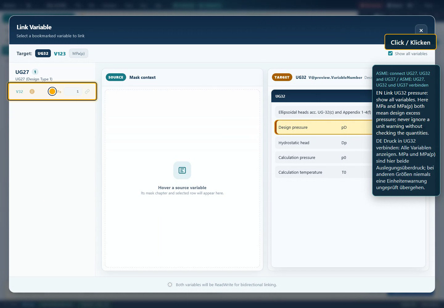
- Check target module, field and unit. The image shows UG32:V123; the proposed bolt case would use ZIEH:V34 in N.
- Check source instance and meaning. The visible ASME source UG27:V32 is not part of the bolt case.
Unaltered original pixels from the approved ASME learning video recorded 6 September 2026 at 80 s. This image explains general controls only and does not establish an executed General Stress case. Original notices remain visible; numbers are separate HTML highlights. Original · Origin and hash.
Chapter 12Inverse check: which force corresponds to the torque?
Hold geometry, friction, bolt count and tightening factor at the torque-case values. Since the relation evaluated is linear in F, force at 50 N m can be recovered proportionally: F=20000×50/51.93644544=19254.30190 N. Substitution into both torque contributions returns 50 N m. This establishes arithmetic, not accuracy of a real torque-to-preload measurement.
Consider repeating that inverse relation at the higher friction values 0.20. The same specified torque then corresponds to a smaller force. Without the actual friction and assembly conditions, a torque-wrench setting therefore does not uniquely determine a complete operating state.
For an actual inverse program calculation, the target quantity must be free and the selected result becomes a given value. Table and thread sizes, however, are discrete choices and cannot be continuously “optimised backwards” without restriction. Source also has different cases for metric, custom and UNC threads and for full and reduced shanks. An inverse force comparison must not change those selections unnoticed.
The reference file includes both algebraic inversions: force from 0.025 mm KRVE extension and force from 50 N m ZIEH torque. Neither is presented as an executed inverse UI run or an allowable limit.
Back to top ↑Chapter 13WRC and WRCK: interpret local loads correctly
WRC treats a cylindrical shell and WRCK a spherical shell under external nozzle loads. Field definitions distinguish radial force, two shear forces and three moments. In WRC, V1 is positive toward the shell, V2 is circumferential and V3 longitudinal. WRCK uses separate Y/X labels for V2/V3. Do not transfer a six-component load vector without checking axes and signs.
Also document the moment reference point. A moment at a piping-model node and one at the nozzle-shell junction can differ by the lever-arm contribution of a force. Program input must describe the condition required by the local model. E912 is explicitly registered as load transformation for horizontal vessels on two saddles; that step also needs matching geometry and its own review.
WRC/WRCK outputs are organised by points A to D, components and upper/lower or inner/outer sides. A stress number without that identification is incomplete. Read membrane and bending components together with the selected evaluation and associated load state. German source labels identify wall fields V8/V10 as including allowances; shorter English labels must not erase that information.
Internal pressure V147 is a separate input in addition to six external loads. Shell and nozzle material and safety data are also separate. An external-load case without full pressure and material definition is therefore not a complete strength assessment. This handbook provides no invented WRC/WRCK curve values or numerical stress outputs; it explains the checked fields, options and transfers.
Back to top ↑Chapter 14Review WRC options and FEM transfer
In the inspected WRC source menu, V150 controls extrapolation: 1 permits it, 2 prohibits it, and 3 uses the last curve value at the boundary. Initialisation sets 1 if V150 is unset. That source default does not establish that extrapolation is appropriate for the particular case. Record the mode and relevant geometry ratios; obtaining a number outside an established range does not automatically extend applicability.
The menu also includes local/global stress evaluation through V158, a material option and FEM invocation. Presentation and availability of these desktop routes in a current web run were not executed here. A source menu entry does not establish an operational external FEM environment.
The inspected WRC FEM route uses a managed child instance with identifier 1001. Before transfer, source requires known V1 through V10 and V147. It invokes automatic linking for matching data but then explicitly writes the six load components as values. WRCK instead retains older instance handling with a shape prompt. Force axes are ordered differently:
| FEM target | WRC source | WRCK source |
|---|---|---|
| V31 | −V1 | −V2 |
| V32 | −V2 | −V3 |
| V33 | −V3 | −V1 |
| V34 | −1000×V6 | −1000×V6 |
| V35 | −1000×V5 | −1000×V5 |
| V36 | −1000×V4 | −1000×V4 |
As a pure transformation check, source loads [1000, −200, 300 N; 10, −20, 30 N m] become [−1000, 200, −300 N; −30000, 20000, −10000 N mm] in the WRC route. In the WRCK route the first three values are [200, −300, −1000 N]. This is a reproduced source transfer, not an FEM run. After changing loads, recheck the actual transferred values; these six written loads are not established continuously updated connections.
Back to top ↑Chapter 15Expansion joints, wind loads and special components
An expansion-joint case starts with geometry and movement. EJMA and EJMR represent different bellows geometries and registered editions. Define axial, lateral or angular movement with load state and cycles before transferring a spring reaction into piping. A small reaction moment alone establishes neither pressure capacity nor life. ELKR separately addresses an elasticity criterion for spatial piping; distinguish that role from a complete piping model.
For wind and live loads, first derive loading appropriate to the structural model. WIND, VERK and ANBA describe different tasks or references; KSTA addresses moment, shear and stress distributions in guided columns. Site assumptions, height segments, projected areas, attachments, supports and guides therefore belong in the same project description. A single wind-force value does not replace a documented distribution over height.
For a horizontal vessel on saddles, assign additional forces to the BS55 case and, where appropriate, a matching load transformation. WRC evaluates local attachment loading in a shell; a saddle or overall structural model represents a different spatial scope. Required global and local assessments should use the same load states while retaining their distinct result meanings.
WARZ, LOBO, K10A, ECKA, SPAR, TEM and WTOR address distinct components or mechanisms. References range from company standards through AD/EN/TEMA bases to unspecified methods. Use the package map to choose the task, and verify conditions and geometry before entering values. This edition does not validate those families through fully executed numerical examples.
Back to top ↑Chapter 16Field reference and translation guidance
The 71 selected fields connect visible tasks to stable variable numbers. Units describe the quantities used here; account for differing display units before transfer. Some incomplete English source labels were clarified editorially; original texts remain in the source snapshot. WRCK uses the distinct axis mapping explained in the WRC chapter for its first load fields.
KRVE
| Field | Label | Unit | Meaning in workflow |
|---|---|---|---|
| V1 | Pre-stressing force bolt | N | Force per bolt considered |
| V2 | Clamping force of the components | N | Equal to V1 in basic assembly case |
| V3 | Outside thread diameter | mm | Nominal outside diameter |
| V4 | Outside diameter of head support area | mm | Head bearing; determines sleeve case |
| V5 | Length of the smooth shank | mm | Plain shank segment |
| V6 | Length of reduced shank | mm | Reduced shank segment; zero here |
| V7 | Length of thread (not been bolted in) | mm | Free thread length |
| V8 | Nominal cross section of the bolt shank | mm² | Nominal area calculated from V3 |
| V9 | Smooth shank cross-sectional area | mm² | Area associated with V5 |
| V10 | Cross-sectional area of reduced shank | mm² | Area associated with V6; retain a positive value even at zero length |
| V11 | Cross section of the bottom of the thread | mm² | Root area; not an arbitrary tensile-stress area |
| V12 | Outside diameter of the sleeve | mm | Outside dimension of clamped sleeve |
| V13 | Diameter of hole which passes | mm | Clearance hole |
| V14 | Grip of bolt-loaded parts | mm | Grip length |
| V15 | Modulus of elasticity bolt material | N/mm² | Bolt elastic modulus |
| V16 | Modulus of elasticity of clamped parts | N/mm² | Clamped-parts elastic modulus |
| V17 | Equivalent cross section | mm² | Case-dependent equivalent area |
| V18 | Compliance of the bolt | mm/N | Bolt compliance |
| V19 | Compliance of stressed parts | mm/N | Clamped-parts compliance |
| V20 | Elastic long. deformation of the bolt | mm | V1×V18; extension |
| V21 | Elastic long. deform. of stressed parts | mm | V1×V19; compression magnitude |
| V24 | Flange bolt-sleeve - limiting case | mm | Limiting dimension V4+V14 |
| V29 | Value for D_A in Case 1 and 2 | mm | Limited dimension used for equivalent area |
ZIEH
| Field | Label | Unit | Meaning in workflow |
|---|---|---|---|
| V1 | Maximum bolt load (bolting-up + operat.) | N | In inspected branch maximum of V33, V34, V38; total force |
| V2 | Pitch diameter of the thread d2 | mm | Thread pitch diameter |
| V3 | Diameter of drill hole Db | mm | Hole diameter under bearing |
| V4 | OD of the contact face of the bolt head | mm | Outside bearing diameter |
| V5 | Friction coefficient u'' (head/support) | — | Head/nut bearing friction |
| V6 | Friction factor (thread) | — | Thread friction |
| V7 | Thread flank angle | ° | Thread flank angle, not helix angle |
| V8 | thread pitch P | mm | Thread pitch |
| V9 | Thread type | — | Thread type; verify metric/custom/UNC |
| V10 | tan(beta) | — | Tangent of helix angle |
| V11 | tan(rho') | — | Friction-angle helper |
| V14 | Frictional moment of the thread | N mm | Thread contribution per bolt |
| V15 | Frictional moment of the head | N mm | Bearing contribution per bolt |
| V16 | Bolting torque | N mm | Sum after multiplication by V54 |
| V18 | Number of bolts | — | Number of bolts with equal load allocation |
| V19 | Bolting torque | N m | V16/1000, per bolt |
| V25 | Root diameter bolth thread | mm | Thread root; distinct from V2 |
| V26 | Existing stress operation | N/mm² | Operating stress; separate load state |
| V33 | Min req bolt load (operating) FSB | N | Minimum total operating force |
| V34 | Min req bolt load (bolting-up) FDV | N | Minimum total assembly force; connection target |
| V38 | Minimum total bolt load during test | N | Minimum total test force |
| V39 | Actual test stress | N/mm² | Test stress |
| V40 | Existing stress bolting up | N/mm² | Assembly stress |
| V41 | Utilization mounting | % | Assembly utilisation |
| V42 | Utilization operation | % | Operating utilisation |
| V43 | Utilization test | % | Test utilisation |
| V49 | allowable stress at mounting acc. VDI 2230 | N/mm² | Allowable assembly stress; separate relation |
| V50 | Allow. Bolting torque acc. VDI 2230 | N mm | Separate allowable VDI torque; not V19 |
| V51 | Appropriate minimum cross-sectional area of the bolt | mm² | Area appropriate to bolt type |
| V52 | Allowable assembly force per bolt | N | Allowable assembly force per bolt |
| V54 | Tightening factor per table 8 | — | Tightening factor; explicitly 1 in reference |
| V61 | Effektive diameter bolt head or nut face | mm | Mean bearing diameter |
WRC
| Field | Label | Unit | Meaning in workflow |
|---|---|---|---|
| V1 | Radial force (+ direction shell) | N | Positive toward shell according to field definition |
| V2 | Shear force in circumferential direction | N | Circumferential component |
| V3 | Shear force in longitudinal direction | N | Longitudinal component |
| V4 | Circumferential moment | N m | Circumferential moment |
| V5 | Longitudinal moment | N m | Longitudinal moment |
| V6 | Torsional moment | N m | Torsion |
| V7 | Outside diameter of cylinder | mm | Cylinder outside dimension |
| V8 | Vessel thickness | mm | Shell wall including allowances in German source |
| V9 | Nozzle outside diameter | mm | Nozzle outside dimension |
| V10 | Nozzle wall thickness | mm | Nozzle wall including allowances in German source |
| V11 | Internal corner radius (welding seam) | mm | Transition radius |
| V14 | Stress intensity factor Kn (membrane) | — | Membrane stress amplification |
| V15 | Stress intensity factor Kb (bending) | — | Bending stress amplification |
| V150 | Type of extrapolation | — | 1 extrapolate /2 prohibit /3 last value |
| V158 | Stress evaluation local/global | — | Local/global evaluation in source menu |
| V180 | My FEM Modul | — | Historical FEM reference; current source manages child instance |
Chapter 17Troubleshooting and common questions
Is the entire package independent of standards?
No. It includes general helper models and explicitly named DIN, AD, EJMA, WRC, TEMA and company-standard methods. The package map gives the actual reference; missing years are not invented.
Are MECK/ECKA or WND/WIND identical?
Similar metadata do not establish aliases. MECK and WND have no confirmed web registration in the inspected catalog. This handbook preserves that gap and proposes no unsupported redirection.
Why is compliance such a small number?
Its unit is mm/N. Under 20000 N, a compliance of 1.7×10⁻⁶ mm/N produces about 0.034 mm extension. Never compare it directly with stiffness in N/mm.
Why does KRVE clamping force equal preload?
The inspected basic relation describes assembly preload and sets V2=V1. It does not completely assess an additional service force and its effect on residual clamping.
May an area be zero when its associated length is zero?
All denominator areas remain positive in the documented calculation. Otherwise l2/A2 becomes 0/0 even though no reduced segment is present. Here l2=0 and A2=201.06192983 mm².
Why do larger sleeve diameters eventually stop changing the result?
KRVE case 2 limits the diameter used for equivalent area to head-bearing diameter plus grip. That is a specific model rule, not a general statement about real component stiffness.
Is ZIEH:V1 force per bolt?
The torque relation considered divides V1 by V18. V1 is total force there; V18 is bolt count. At n=1 total and individual force are numerically equal; that equality must not be carried over to n>1.
Which conditions enter the maximum?
When calculating V1, the inspected source branch takes the maximum of V33 operation, V34 assembly and V38 test. The older short label names only assembly and operation and is insufficient on its own.
Why do V16 and V19 differ by a factor of 1000?
V16 uses N mm and V19 N m. In the torque case they represent the same physical quantity per bolt in different units.
Is the thread/bearing torque split always the same?
No. Geometry and the two separate friction values determine the contributions. The diagram shows only the calculated split for the teaching case.
Is a tightening factor of 1 recommended?
No. It removes additional scaling in the analytical basic case. A real assembly method and its scatter must be established separately. Source uses V54 as a multiplier in this torque branch.
Why does calculated force decrease at fixed torque when friction increases?
In the documented relation, more torque is required by friction. A fixed torque therefore corresponds to a smaller force. This is not an instruction to change surfaces without reassessing assembly.
Does a low tightening torque establish strength?
No. Required and allowable torque are different results. ZIEH has separate assembly, operating and test quantities; the isolated torque case does not assess all of them.
Can WRC interpret positive force differently from the piping calculation?
Yes. WRC:V1 is positive toward the shell according to its field definition. Check source axes, moment reference point and signs before transfer.
Does permitted extrapolation establish applicability?
No. V150 controls behaviour outside tabulated curves. It does not approve the model used. Document mode, geometry and affected curve group.
Do FEM forces automatically remain current after a source change?
The inspected transfer routines explicitly write the six load components as values. These force rows are therefore not established persistent links. Recheck transfer after changes.
Are WRC and WRCK FEM calls the same route?
No. WRC uses a managed child instance in the inspected source; WRCK retains an older route with a separate shape prompt. Force axes are also mapped differently.
What do the images and downloads establish?
Diagrams show analytical models. The original image comes from an approved ASME demo and explains general controls only. JSON and script reproduce source calculations; they are not real General Stress project archives or executed runtime evidence.
Chapter 18Document results and retrieve them
A result report should combine component, assembly/operation/test state, reference basis, geometry, materials and load origin. For bolts, individual and total force, count, friction and tightening factor belong in the same report. Present required quantities and allowable limits separately; calculated torque alone is not a complete approval result.
For WRC/WRCK, load axes, reference point, signs, evaluation points and extrapolation are part of the result. If an FEM case is added, document its own geometry, materials, restraints and actually transferred loads. An existing child-module reference does not establish a successfully calculated FEM assessment.
Save initial and changed states under separate names. After reopening, verify module instances, design types, given/sought states and connections. For reproducible runtime evidence also record loaded application/plugin versions and calculation status. This edition claims no observation of such a complete General Stress run.
Search filters chapters using multiple words; direct chapter anchors reveal their targets again. Printing includes chapters hidden by search. DE and EN share the same anchors, and the entry page follows the application's global language. Locally opened language files remain readable and searchable. JSON cases and the recalculation script work without a SOL ALPHA service.
Back to top ↑Chapter 19Sources and limits of this edition
The source snapshot records 24 configured members, inspected repository revisions and hashes of reviewed files. KRVE, ZIEH, WRC and WRCK received closer review through field definitions, web masks and selected equation/routing blocks. Other members were classified using their actual registered tasks and references.
The complete example specification explicitly declares source-only evidence. The standalone recalculation script can run with Node.js and prints the same references. It launches no calculation engine. Checks establish arithmetic and documented relationships, not complete standards compliance, material suitability or parity with a loaded plugin.
Primary sources support interpretation: VDI 2230 Part 1 for scope and assembly terminology, EJMA publications for the edition currently offered, and WRC for authorised bulletin access. Checked 7 September 2026; complete paid standards or curve tables are not reproduced.
The connection-dialog image is an unaltered approved ASME video frame, explicitly general operating context only. Provenance and image hash remain traceable. The two engineering diagrams are original conceptual depictions of the stated reference calculation. No customer archives or invented SOL projects were used.
A future extension needs an executed normal/change/connection/reopening run with a known build, checked real material and assembly selections, and complete numerical examples of further forms. These chapters already explain the specifically established tasks and limits. A completed package overview does not automatically complete separate detailed handbooks for all members.
Back to top ↑