WTS Package – Heat exchanger calculations
Understand, configure, recalculate and assess shell-and-tube heat exchangers.
A complete learning and reference path: engineering principles, operation, child modules, inverse calculation and result review. Screenshots show the English interface; prose and figure legends are fully available in English.
No matching chapter. Try another term.
Chapter 01Understanding WTS: purpose, scope and limits
WTS is SOL ALPHA's thermal and hydraulic calculation system for shell-and-tube heat exchangers. One fluid flows inside the tubes and the other through the shell space. Heat passes through the tube wall while the two fluids remain separate in intended operation. WTS connects the process duty to an actual geometry: How much heat must be transferred? Which temperatures can be reached? What area and bundle length are required? What pressure losses result?
This handbook is for new users unfamiliar with the interface and experienced users who want to understand the connected child chapters. It explains both the operating procedure and the engineering meaning of the quantities. It does not replace the underlying technical literature or a complete safety and mechanical design assessment.
Tasks supported by WTS
- Single-phase liquid and gas duties, including water/water, oil/water and gas/glycol cases.
- Applicable pure-fluid condensation cases; fluid, side, phase and installation orientation determine the calculation path.
- Tube layouts, tube pitch, passes, shell and tube dimensions, and baffles.
- Required and available heat-transfer area, heat-transfer coefficients, pressure losses and selected actual outlet temperatures.
- Variations of existing equipment, changed operating cases and supported inverse calculations.
- Extensions for special tubes, double-pipe arrangements, vibration assessment and documentation, subject to installation and entitlement.
Three different engineering tasks
- Design
- The process duty is known and a suitable geometry is sought. A calculated minimum area is only an intermediate result.
- Rating an existing exchanger
- The installed geometry is fixed. You check whether it meets an operating case or determine the outlet temperatures it can actually achieve.
- Comparing an older project
- You compare saved constraints, geometry, calculation edition and newly calculated results. A historical number is not proof that the original calculation was fully converged.
Version and reading order
The technical reference is the reviewed WTS fix state of 7 September 2026. The handbook is delivered separately on main13.0. Publishing this handbook does not imply that the calculation fix branch has already been integrated into every deployed application. Check the version of the installation you actually use.
Start with the principles and worked example. Then use the child-module chapters and field index for reference. Capabilities established from source are not presented as independently accepted live operating cases.
Back to top ↑Chapter 02The operating principle: constraints, results and solver
SOL ALPHA does not impose a rigid distinction between permanently designated input and output fields. Its internal equation solver uses known quantities to determine unknowns supported by the selected module path. The same physical quantity can therefore be an input constraint in one task and a calculated result in another.
This flexibility does not mean every mathematical rearrangement is available in every module. Selection fields, discrete tube counts, tables, validity limits and iterative solution paths impose restrictions. Several geometries may satisfy the same thermal duty. An inverse calculation consequently needs an unambiguous question.
Four questions for each important field
- Is the value known? An empty or unknown result is not zero.
- Is it a constraint or a result? A calculated value may change after another input.
- Is it fixed? A fixed constraint should not be replaced by another equation.
- Is it connected? Another module instance or child chapter may be its authoritative source.
Entering values safely
Click the correct numerical field, enter the value and confirm it, for example using Tab. Wait for processing to finish before changing more dependent fields. Afterwards, check the value actually accepted and its displayed unit.
The general SOL ALPHA input system also supports expressions and units. 100 + 200 is arithmetic, not a list. 1 bar is a physical input that can be converted into the field's compatible unit. For WTS, pay particular attention to whether a pressure field requires absolute pressure. Unit conversion does not by itself convert gauge pressure into absolute pressure.
Reading field colours
In the standard mask, calculated numbers commonly use a teal colour or corresponding field style, while ordinary constraints look different. Connected variables and highlighted dependencies can receive additional colours or markings. Colour is a navigation aid, not sufficient evidence on its own: inspect Variable info, fixed status and connection source when uncertain. Themes, focus and active highlights can alter appearance.
Releasing a variable
To prescribe a previously calculated result, a suitable other constraint must become free. Open the field's context menu and use the available release or inverse-calculation action. Check which quantity the solver determines afterwards. Do not release several boundary conditions indiscriminately: this may leave the problem underdetermined or move it towards a different geometry.
In WTS the consequences often span several chapters. Changing tube count may affect SPIE, velocities, heat-transfer coefficients and pressure losses. Changing fluid or temperature propagates through fluid properties to required area. Wait for the complete calculation to finish and inspect its messages.

- Shell mass flow: the prescribed 3 kg/s in this case.
- Tube mass flow: a calculated result in this case.
- WTS and its children in the project tree.
Unaltered frame from the 6 September 2026 demo; English UI with the original bilingual video captions. Full-size original
Chapter 03Engineering foundations of heat transfer
The tube side is not necessarily the hot side
Inside/tube side and outside/shell side identify the flow space. Either can release or absorb heat, depending on the duty. Assign process data to the actual connections and flow arrangement rather than relying on the colours in a sketch.
Energy balance and signs
For a single-phase fluid with a suitable mean heat capacity, this is the most useful preliminary check. In the WTS example shown here, cooling produces a negative duty and heating a positive duty. With no heat loss, Q̇ᵢ + Q̇ₐ ≈ 0 for that case. Compare magnitudes when assessing transferred duty, but retain signs when checking the balance. For phase changes or strongly varying properties, an enthalpy balance Q̇ = ṁ · Δh is more appropriate; the simple cp relation is insufficient on its own.
Driving temperature difference
Finite area transfers heat only with a driving temperature difference. For ideal countercurrent flow the terminal differences are ΔT₁ = Th,in − Tc,out and ΔT₂ = Th,out − Tc,in. For positive terminal differences:
If the two differences are equal, the limiting value is that common difference; the expression 0/0 is not a physical failure. Negative or vanishing temperature approaches, however, require engineering review. A temperature cross is not inherently impossible in countercurrent flow: the local driving difference matters, not simply the comparison between the two outlet temperatures.
Area, film coefficients and overall coefficient
This is an overview of the usual thermal relationship, not a complete substitute equation for every WTS special case. FN accounts for the actual flow arrangement relative to an idealized temperature profile. Additional corrections, such as those associated with longitudinal baffles, may apply.
The film coefficients αᵢ and αₐ each describe heat transfer between a fluid and the wall. The overall coefficient k combines both film resistances, tube-wall conduction and fouling. For a plain cylindrical tube, on an outside-area basis, the schematic relationship is:
All quantities must use a consistent area basis. Finned tubes and other special geometries require additional area ratios and efficiencies. Never import an external k value without knowing its reference area.
Why higher velocity is not always better
Higher velocity can improve heat transfer, but often increases pressure loss, pumping requirements, erosion or vibration loading. Reducing baffle spacing changes crossflow, window flow, end zones and the number of turns simultaneously. These effects are coupled: a seemingly optimal α value does not establish an optimal exchanger.
Understanding dimensionless quantities
The Reynolds number Re = ρ·v·d/μ compares inertial and viscous effects; the Prandtl number Pr = cₚ·μ/λ relates momentum and thermal transport. Characteristic length and validity range depend on the child module. A familiar pipe-flow threshold must not be transferred uncritically to complex shell-side flow.
Chapter 04Preparation: which information do you need?
Start by separating process requirements, existing construction and adjustable design variables, not by entering as many numbers as possible. Record source, unit and status for each quantity. A quotation value, an operating measurement and a freely chosen assumption do not have the same authority.
Process information for each side
- Fluid, phase and, where applicable, composition, concentration, salinity or humidity.
- Inlet and target outlet temperatures; for a rating case, possibly only inlet temperatures as fixed constraints.
- Mass flow or a clearly defined volume flow. For gases distinguish actual and reference-condition volume flow, and document the reference state.
- Absolute inlet pressure and allowable pressure loss. Inlet and outlet densities can differ for gases or phase-changing fluids.
- Fouling assumptions, heat losses and special requirements such as freeze protection or maximum film temperature.
Construction information
For existing equipment, obtain at least the applicable configuration, tube dimensions, thermally active length, tube count and passes, shell geometry and internals. For a tube layout, pass lanes, plugged or support tubes, window zones and saved individual tube positions matter. Identical total tube counts do not by themselves describe identical layouts.
Leave the right quantities open
If WTS is to determine tube-side mass flow from duty and temperatures, do not also impose a contradictory fixed mass flow. If you seek the actual outlets of existing equipment, all target outlet temperatures must not simultaneously constrain the answer. State the task explicitly: “For this exchanger, with these inlets and flow rates, I want to determine …”.
Unit check before calculating
Common mistakes are kg/h instead of kg/s, mm instead of m, kW instead of W, dynamic instead of kinematic viscosity, and percent instead of mass fraction. For example, 3 kg/s equals 10,800 kg/h, and 323.9 mm equals 0.3239 m. These conversions do not change the physical task. Accidentally entering 323.9 into a metre field does.
Pressure reference must be correct as well as the unit. Use the appropriate absolute pressure rather than applying a generic offset without knowing ambient conditions. Temperature differences and absolute temperatures also obey different conversion rules.
Back to top ↑Chapter 05First start: from module browser to calculation mask
- Open a separate demonstration or practice project. Do not use an unsaved production design as an exercise workspace.
- Search the module browser for WTS. Select the heat-exchanger module and read its description. A special version offered alongside it is not automatically the standard configuration.
- Open the module. Where the launch path requires it, the basic-data selection dialog appears. A loaded project may instead show its saved mask immediately.
- Select both fluids and phases in basic-data selection. Then check tube and shell geometry, bundle type, installation orientation, baffles and any special tubes.
- Review the summary and confirm the configuration using the offered action. A check mark in the dialog navigation indicates completeness of dialog entries, not engineering suitability.
- Complete operating data in the calculation mask from top to bottom. After each useful input group, check accepted values, units and messages.
- Inspect WTS child chapters in the module tree to understand the origin and state of important intermediate results. Return to the parent WTS afterwards.
- Review evaluation and results. Save a clearly named practice variant only once you understand which values are fixed constraints and which have been calculated.
Finding your way around
Project modules and indented child chapters appear on the left, the active calculation mask in the centre, and information and warnings on the right. Their exact position depends on the layout. WTS has several thematic mask sections; deliberately scroll to evaluation and results instead of treating the upper operating-data area as the whole calculation.
The basic-data button or module-specific special menu returns to configuration. Confirming again is not a view-only operation: selections and defaults may be applied. Save a variant before a major reconfiguration and compare the governing constraints afterwards.
When a dialog is waiting
An open selection, tube-layout or fluid-property dialog is part of the active calculation workflow. Close it deliberately with Apply or Cancel. Repeated background recalculation does not replace the pending decision. If a dialog remains open despite an appropriate selection, capture the message and last action instead of opening several more WTS instances.
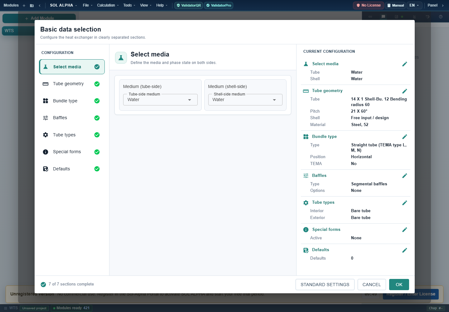
- The seven areas guide configuration.
- Select tube and shell fluids separately.
- Review the summary before applying.
- OK applies settings; checkmarks do not approve the engineering design.
Existing program screenshot; capture time not independently documented. Full-size original
Chapter 06Selecting fluids, phases and properties
Fluid selection is part of the calculation, not merely a label. It determines which property module WTS creates and which temperatures, pressures and compositions it uses to evaluate properties. Open the basic-data dialog and configure tube and shell sides separately. Then check the transferred settings in the main mask.
Procedure for each side
- Assign the actual fluid to the tube or shell side. The hot fluid does not have to be inside the tubes.
- Select the fluid and an available phase. Liquid, gas and condensation do not use the same model.
- Supply the requested additional information: glycol product and concentration, frost protection, salinity, oil grade, acid concentration or gas composition.
- Apply the selection. Enter operating pressure and temperatures in the main mask, using the correct pressure reference.
- Open the corresponding property chapter and inspect density, heat capacity, thermal conductivity and viscosity. Phase change also requires saturation state, enthalpy, vapour quality and latent heat.
Water, steam, gases and mixtures
H2O provides water/steam states; a liquid-water calculation and steam condensation are nevertheless different duties. Air, nitrogen, oxygen, helium, CO₂ and ammonia have their own routes. Natural gas distinguishes predefined L/H cases from free composition input. Humid gas uses HX; condensate and latent heat cannot be treated as though the gas were dry.
Glycol does not automatically mean an arbitrary water/glycol mixture. Choose the offered product and supply its concentration or frost-protection parameter as requested. Oils require a product type and, where applicable, ISO grade and density. For acids, sodium hydroxide, sucrose, seawater and beer/wort, composition is part of the duty. A fluid name alone is insufficient.
Free property input and external property sources
Free input / SDAT is useful when reliable properties are available outside the built-in selection. Record their source, temperature and pressure range, composition and units. A single room-temperature value is not an adequate basis for a wide temperature change or strongly temperature-dependent viscosity. PROP/Proper and STAB are separate property routes; the available selections depend on installation and datasets.
The fluid reference maps all 32 historical fluid identifiers to property modules. Historical glycol identifier 10 is not a replacement for current selection 15.
Back to top ↑Chapter 07Defining tubes, shell and passes
The basic-data dialog groups fluids, geometry, bundle, baffles, tube forms, special forms and defaults. Visible and editable fields depend on the selection. Start with a simple geometry corresponding to the real equipment, then add any special features.
Tubes and shell
Distinguish tube outside diameter V24, inside diameter V25 and wall thickness V305. For an ordinary round tube the geometric relationship is di = da − 2s. V19 is a heat-transfer wall-thickness quantity and cannot automatically replace every construction wall dimension. Shell outside diameter V41, shell wall thickness V42 and shell inside diameter V54 form a separate dimensional chain. Select material and conductivity appropriate to operating temperature.
Use the offered tube and shell selections where appropriate. Library values simplify recurring dimensions but must still agree with drawings and supplied equipment. Save or delete personal table entries deliberately; a teaching example does not require changes to shared master data.
Pitch and passes
Transverse and longitudinal pitches V43/V44 and pitch angle V93 define the tube arrangement. Tube-side passes V55 distribute the tube cross-section across successive flow paths. Shell-side passes V97 describe a different arrangement. Doubling the number of passes therefore neither doubles the duty in general nor automatically doubles effective area. It changes velocity, heat transfer, pressure loss and temperature arrangement.
Three lengths that must not be confused
- Required bundle length V46
- The calculated length for the current thermal duty and selected geometry.
- Actual active tube length V60
- The length available for effective heat transfer. Together with tube count and reference diameter, it determines available area.
- Total tube length V196
- A construction dimension including other length contributions. Do not use it as active length without checking its definition.
Fixed dimensions or design targets?
For existing equipment, its fixed dimensions must remain intact. In a new design, desired velocities V61/V62, minimum clearances or length/diameter limits can serve as design settings. These target values are not the calculated operating velocities V53/V94. After any layout change, recheck tube count, areas and both pressure losses.
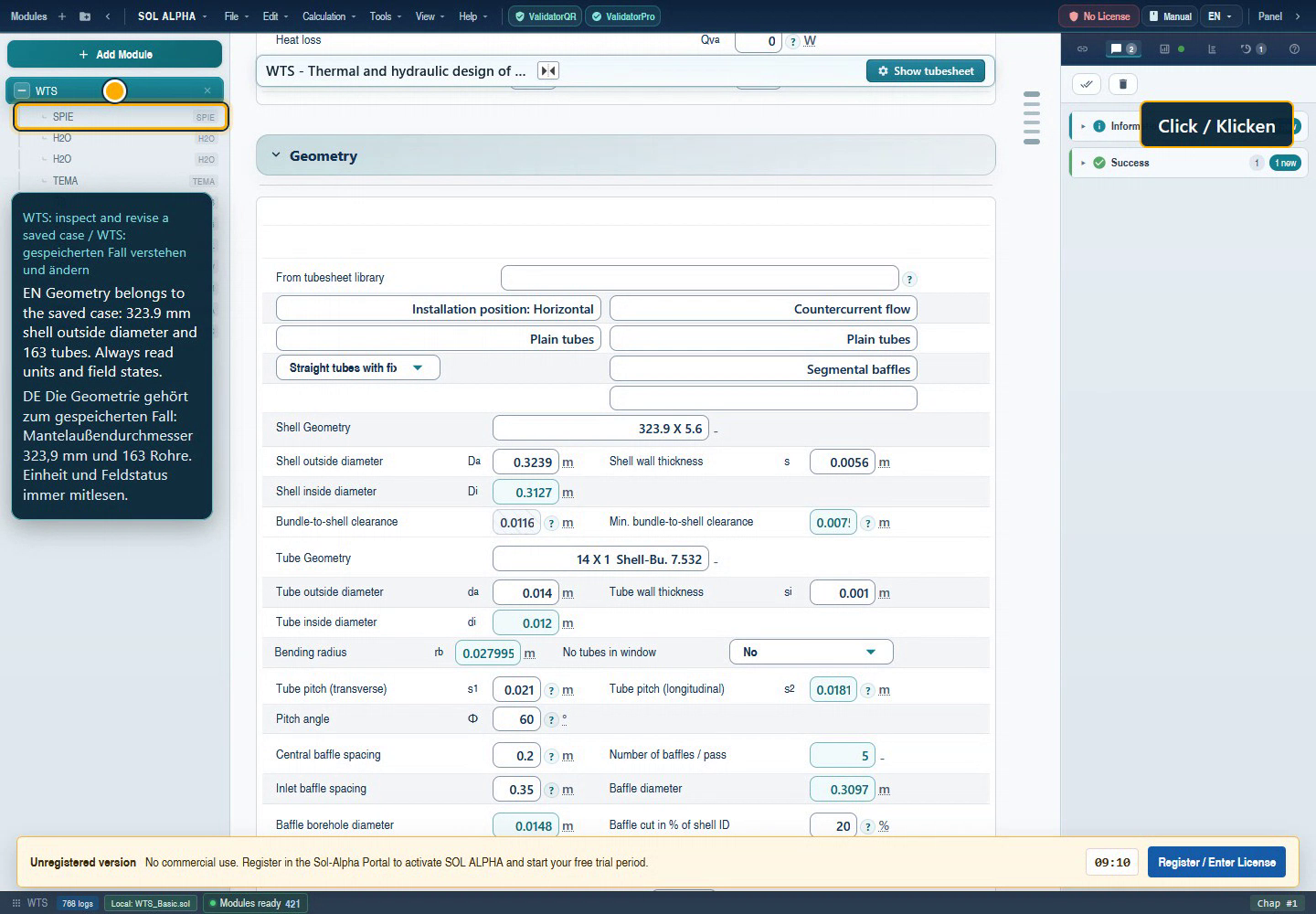
- Shell dimensions: outside, wall and inside form one chain.
- Tube dimensions: 14 × 1 mm gives 12 mm inside.
- Regular spacing and first spacing are separate fields.
Unaltered frame from the 6 September 2026 demo; English UI with the original bilingual video captions. Full-size original
Chapter 08Baffles, windows, clearances and nozzles
Baffles guide shell-side flow and support tubes. Their geometry affects cross-flow, window flow, leakage and bypass streams, pressure loss and vibration. A thermally favourable change can be hydraulically or mechanically disadvantageous.
A practical input sequence
- Select the actual baffle arrangement. Standard segmental baffles, no internals, disk-and-doughnut and spiral variants follow different paths.
- Check window height V56 and any target cut V105. Percentage values follow the field definition; they are not millimetres.
- Distinguish regular baffle spacing V58 from tubesheet-to-first-baffle distance V59, especially for existing equipment.
- Check count V115, baffle diameter V117, tube-hole diameter V109, thickness V314, bundle-to-shell gap V57 and sealing strips V118.
- Enter actual nozzle inside diameters V70–V73. Nominal size and outside diameter are separate quantities, not substitutes for the open flow area.
- Recalculate and assess heat transfer, shell pressure loss, window velocities and nozzle velocities together.
Explicitly prescribing the first baffle distance
The special function for prescribing tubesheet-to-first-baffle distance changes a design rule: it permits an entered first distance below the shell-based spacing rule otherwise used. It is not a general override of geometry or mechanical limits. Use it only for a documented construction, enter V59, and verify that the value survives recalculation and reopening. Regular spacing V58 remains a different variable.
Why closer spacing is not always better
Closer baffles can increase cross-flow but often increase pressure loss. Clearances and tube holes allow part of the flow to bypass ideal cross-flow. An apparently favourable external heat-transfer coefficient is therefore questionable if clearance inputs are missing or unrealistic. Never optimise V17 alone: also inspect V65 and the vibration assessment.
U-tubes and special baffles introduce further clearances and supports. Spiral baffles have additional angles, cycle counts and central diameters. Use the field reference for identification and the relevant child module to assess the applicability of a variant.
Back to top ↑Chapter 09SPIE: understanding, checking and freezing a tube layout
SPIE represents the tube layout: tube positions and count, pass lanes, pass arrangement, window regions and construction boundaries. This is more than a drawing. Tube count and open flow areas affect heat transfer, surface area and pressure loss. A different layout can therefore change results even when temperatures and mass flows remain unchanged.
Viewing is not redesigning
- Select the correct WTS chapter, particularly in a project containing several exchangers.
- Use “Show tubesheet” when a layout is available, or open the SPIE child belonging to that WTS.
- Check total tube count, passes, lanes, edge clearances and windows. Compare them with V47 and the parent WTS geometry.
- Close the view without changes when inspecting only. Redesigning or choosing a different library entry is an intentional geometry change.
When should a layout be frozen?
Freeze a layout when rating existing equipment or when an approved tube arrangement must remain unchanged. “Freeze/edit tube layout” changes the layout state and associated SPIE fixed state; the editing route can open the editor. “Frozen” does not mean all thermal variables are fixed. Mass flow, properties and duty can still be recalculated.
In the reviewed source, unfreezing deliberately releases selected geometry settings and clears library associations. Save a copy first. Default rules may select a different shell/tube arrangement after unfreezing. Check the returned values as well as the drawing.
Libraries and reuse
A saved layout is useful for recurring construction sizes. Before applying it, compare tube diameter, pitch, lanes, passes, shell and internals. A familiar name is insufficient. Viewing a project layout is not the same operation as saving or deleting a library entry.
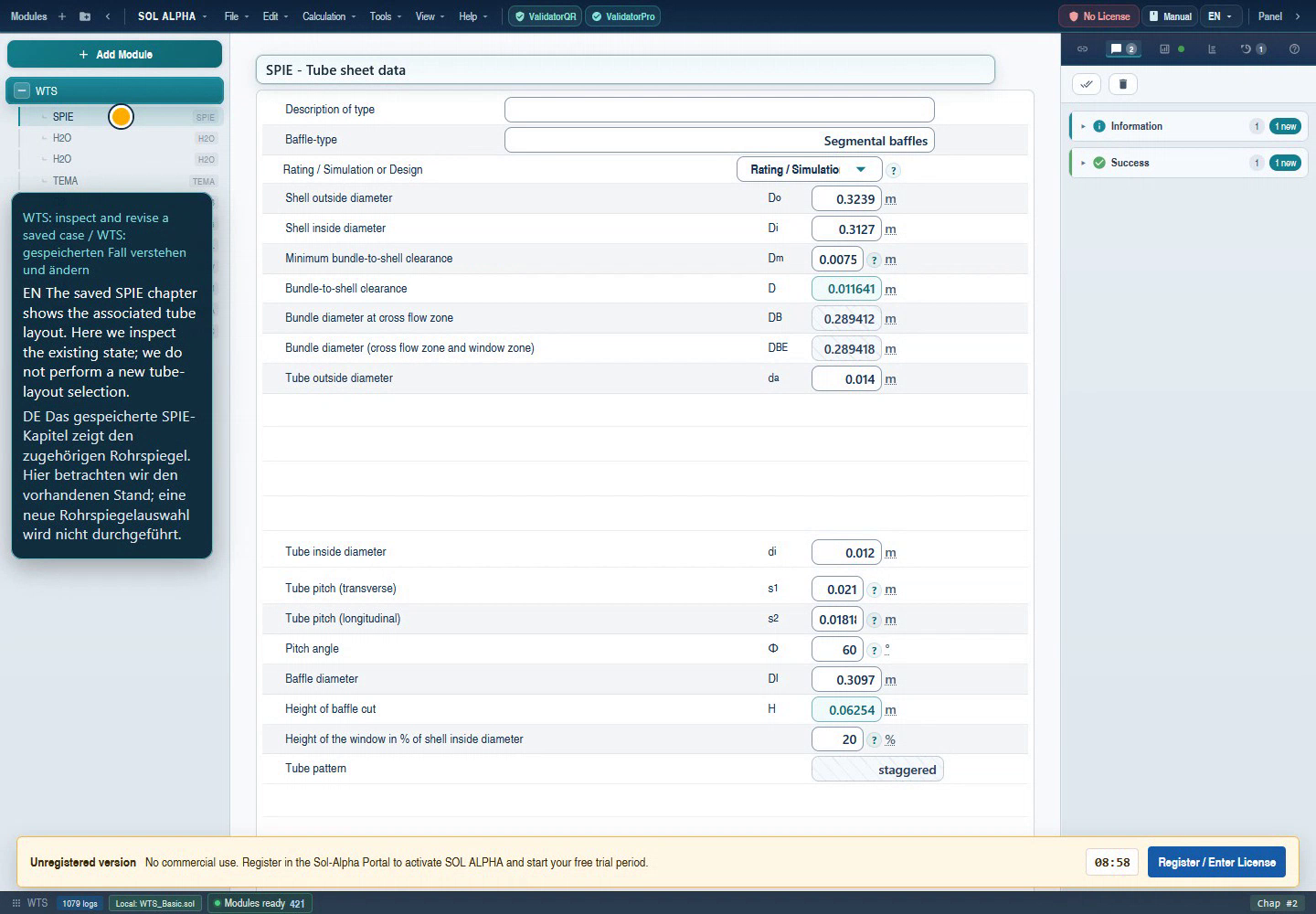
- The associated SPIE chapter is selected.
- Check rating/design mode and shell dimensions.
- Compare inside diameter and pitch with WTS.
Unaltered frame from the 6 September 2026 demo; English UI with the original bilingual video captions. Full-size original
Chapter 10How WTS uses its child modules
WTS is the coordinating parent. It assembles the duty and geometry, delegates subtasks to specialised modules and receives their results. Not every child occurs in every calculation. Two H2O chapters may represent the two fluid sides; identical names do not mean they are the same chapter.
The typical interaction
- Operating data determine the heat balance and mean states.
- Property modules supply temperature- and pressure-dependent properties.
- SPIE supplies the actual tube arrangement and geometric quantities.
- GB/GG or selected alternatives calculate heat-transfer coefficients. RDV/LM or alternatives calculate pressure losses.
- WTS combines resistances into overall heat transfer and determines area or length. FN/ZELL handle temperature arrangement where that route applies.
- Changed wall temperatures, properties or geometry may require further passes.
This is a coupled calculation, not a one-time list of independent formula evaluations. Wait for calculation completion and inspect messages. A value already present in a child does not establish that the parent has fully incorporated the new state.
Inspecting a child usefully
- Identify the parent WTS and the fluid side under investigation.
- Open its child in the chapter tree, not an arbitrary same-named module elsewhere in the project.
- Compare transferred temperature, pressure, mass flow and geometry with the parent.
- Inspect assumptions, applicability messages and outputs in the child.
- Return to WTS and check the result transferred back.
The following chapters explain the module groups and their checks. The technical directory distinguishes ordinary children, dynamically selected property modules and conditional special/legacy paths. It does not promise that every named module is available under every licence.
Requirements feed the applicable children; results return to WTS and affect other subtasks. Further passes may be needed.
Chapter 11Tube-side heat transfer: GB and alternatives
GB: the usual smooth-tube route
For single-phase flow in a smooth tube without special internal features, WTS normally uses GB. It receives dimensions, flow and properties; its heat-transfer coefficient returns to WTS as internal coefficient αᵢ, V16. Inspect GB when the tube side dominates resistance or V16 responds unexpectedly.
Check inside diameter, active length, tube count per flow path, mass flow, viscosity and the states used for wall corrections. Higher viscosity can significantly change heat transfer. Changes in passes must consistently change effective flow area and velocity. Reynolds and Prandtl numbers help interpretation; consult the module and its technical reference for the applicability of the correlation actually used.
TWIS, INLR and DRLL
- TWIS – tube inserts
- The WTS insert route uses TWIS. An additional geometry parameter can require input. Use actual insert data; guessing a value simply to dismiss a dialog is not a design procedure.
- INLR – internal longitudinal fins
- Internal fins change area and flow cross-section. Smooth-tube diameter and tube count alone no longer describe heat transfer.
- DRLL – corrugated tube
- This route is used for the corresponding tube form. Actual corrugation geometry and associated resistance must be considered.
- MD – a special subcooling route
- Within a parent KOND duty, WTS can use MD for a vertical falling-film subcooling section. This is not a general alternative to enable in every water calculation.
Prescribing internal heat transfer manually
“Prescribe internal alpha” enables deliberate manual input of V16. It can be used to investigate an externally justified coefficient. Switching the mode clears the previous alpha and Reynolds values; switching back restores automatic calculation. Record the coefficient's source, area basis and operating state. Overriding a child is not evidence that its model is incorrect.
Back to top ↑Chapter 12Shell-side heat transfer: GG and construction variants
The shell side depends particularly strongly on actual tube-layout and baffle geometry. V17 is therefore not a function of mass flow alone. Window flow, cross-flow, lanes, clearances and internals affect the flow distribution.
Which child corresponds to which geometry?
- GG – bundle with internals
- The standard route for smooth tubes with segmental baffles. Other selected baffle forms also feed GG in the current WTS route. Check transferred tube arrangement, spacings and properties.
- GGO – no internals
- WTS uses this route when “no internals” is selected. Simply setting the number of segmental baffles to zero is not equivalent to selecting the correct construction.
- GGRI – external fins
- The low-fin route. Fin diameter, pitch and thickness are additional inputs; note the area basis of the result.
- GGLR – external longitudinal fins
- The longitudinal-fin route, with modified heat transfer and flow channel geometry.
- MB – fin block
- Used for the corresponding fin-block construction. This geometry is not interchangeable with an ordinary smooth-tube bundle.
- GD – double pipe
- Handles the corresponding double-pipe/annular-space route. Annulus dimensions must match the selected tube geometry.
- CIRC – disk-and-doughnut in legacy projects
- The code can retain an existing CIRC chapter. New disk-and-doughnut cases use GG in the inspected branch. A different chapter tree is therefore not automatically a defect.
Prescribing external alpha
As on the tube side, V17 can be deliberately prescribed through a special function. Record its area basis and origin, then check k and required area. With alpha prescribed, a flow change must not be expected to automatically recalculate that same coefficient.
Investigating shell-side discrepancies
Compare geometry between WTS and SPIE first, properties second and the coefficient third. A changed tube count or newly generated layout can change velocity and heat transfer. A plausible number in WTS combined with inconsistent child data is not a dependable state.
Back to top ↑Chapter 13Pressure loss, TEMA clearances and cold start
A thermally adequate design can be hydraulically unusable. WTS distinguishes tube-side pressure loss V64 and shell-side loss V65. Compare each with the agreed limit for this exchanger. Available pump or compressor head must also accommodate the rest of the plant.
RDV and LM
RDV is a tube-side pressure-loss route; special tubes and inserts can use their specific routes instead. LM is a shell-side route. Depending on construction, GGO, GGLR, CIRC or DRRB may also be involved. Inspect the actual child to establish which friction, turning and connection contributions it includes. Do not automatically add a contribution twice.
Nozzle velocities V74–V77 help identify small connection areas. Do not confuse operating gas volume flow with standard volume flow. Density changes and, where applicable, Joule–Thomson effects require separate consideration for gases; JTHO is a conditional WTS route, not a universal temperature correction for every pressure drop.
What TEMA does here
In the inspected WTS route, TEMA supplies geometric settings including minimum bundle-to-shell clearance and minimum baffle spacing. The code halves a diametral bundle-to-shell clearance to obtain a radial gap. Pay attention to that definition. A TEMA child in the tree does not constitute a complete mechanical TEMA assessment of the exchanger.
Cold start
The mask includes separate cold-start temperatures, associated properties and pressure losses V218/V219. This matters particularly for viscous fluids: steady warm operation may show a modest loss while cold startup is much less favourable. Check cold-start conditions independently of the normal heat balance and document which values are known and calculated. This does not replace a time-dependent simulation of the complete startup process.
Back to top ↑Chapter 14Condensation, humid gases and enthalpy
Condensation releases latent heat. A single-phase approximation using constant cₚ and a temperature difference is therefore insufficient. Pressure and saturation state, inlet and outlet vapour quality and any superheating or subcooling must match the duty.
JA routes used by WTS
- JA5
- A route for internal condensation in a horizontal flow arrangement. WTS can assemble the progression through several sections in an EQU child.
- JA3
- A vertical condensation route used according to side and installation. Flow direction and gravity effects must not simply be copied from a horizontal example.
- JA4
- The route used here for external condensation on horizontally arranged tubes. Tube rows and film conditions matter when interpreting the model.
- EQU
- An accompanying results table, with ten evaluated sections in the inspected condensation route. It can display vapour quality, heat-transfer coefficient, overall coefficient, length and pressure loss. Such a table is not automatically an independent second verification.
Humid gas is a separate duty
HX accounts for the humid-gas state. Condensation of water changes enthalpy and gas-phase composition. Check relative humidity, condensate mass flow V251/V252 and the corresponding states. A pure-steam model and a humid gas mixture are not interchangeable.
Before calculating
- Is the fluid a pure condensable substance or a mixture containing non-condensables?
- Does absolute pressure agree with the specified saturation state?
- Is vapour quality a mass fraction as defined by the field, rather than relative humidity?
- Are installation orientation and flow direction correct?
- Is a separate subcooling/superheating zone needed that requires a parent KOND workflow?
Chapter 15FN, ZELL and actual outlet temperatures
A specified outlet temperature initially describes the required process duty. It does not prove that a specified small area can achieve it. In applicable configurations WTS therefore distinguishes target temperatures from calculated actual temperatures.
FN and ZELL
Temperature correction depends on tube/shell passes, arrangement, internals and exchangers in series. WTS selects FN or ZELL in the corresponding route. They are not two arbitrary safety factors to apply in parallel. A route change can remove the child that no longer applies. In certain condensation cases FN is set to 1 and the corresponding actual-temperature calculation is specifically not handled like a single-phase case.
FN factor V80 corrects the idealised temperature arrangement. V324 denotes a corrected logarithmic mean temperature difference. A low factor can indicate an unfavourable pass combination or a difficult temperature duty. Do not manually set it to 1 to remove a warning. An internal lower bound used in a calculation step is not an engineering acceptance criterion either.
Rating existing equipment
- Keep the tube layout and constructed active length fixed.
- Enter inlet temperatures and available mass flows as operating conditions.
- Check which target quantities remain fixed and which actual temperatures the selected route calculates.
- Compare actual outlet values V223/V224 with required values V10/V12 where these fields are offered and known.
- Assess heat balance, area, pressure loss and applicability messages together.
A missing actual-temperature field may reflect a construction limitation or an incomplete state. Manually copying a target value is not a substitute for a calculated actual temperature.
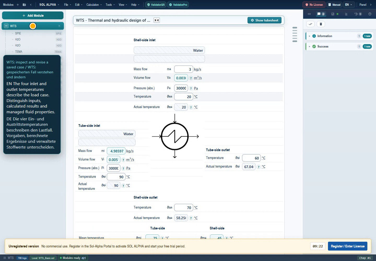
- Tube outlet: target 60 °C; actual approximately 67 °C in the recorded case.
- Shell outlet: target 70 °C; actual approximately 58 °C here.
Unaltered frame from the 6 September 2026 demo; English UI with the original bilingual video captions. Full-size original
Chapter 16Vibration, special constructions and parent packages
RBSA and GV/GVLV
WTS includes an RBSA call for simplified vibration assessment and a separate GV interaction using GVLV. Transferred data include shell/tube dimensions, active length, baffles, fluid states, elastic modulus and thermal expansion. This illustrates why thermal adequacy alone is insufficient: flow and unsupported spans also affect mechanical loading.
Before opening the assessment, check material, temperatures, support spans, baffle thickness and tube arrangement. Inspect transferred values and the assessment criteria in the dialog. Completing GV is not a universal proof against every damage mechanism, including corrosion, fatigue from other loads or manufacturing deviations.
Special tubes and constructions
The basic-data selection includes routes for U-tubes, double pipes, fins, inserts, spiral baffles and other constructions. Safety heat exchangers can have double-wall and contact/barrier-layer quantities. Heated special constructions can require film/wall temperature and heat-flux limits. Use data from the actual construction only.
The WTS source also contains manufacturer- or project-specific identifiers such as BEHR/B_WP, DIET, HSCO, NEWC and Striko/OhmEx routes. These branches are not a universally available toolkit. This handbook does not replace their complete proprietary design rules. The technical directory makes them discoverable while explicitly marking them as conditional or installation-dependent.
When WTS is itself a child
Within parent KOND/UVERD workflows, WTS can represent an individual zone. Several WTS special functions are then intentionally disabled, including independent basic-data or tube-layout changes. Change the configuration through the owning parent workflow instead. A disabled command is not automatically an operating error.
KB/GA and further special routes appear in the technical call inventory. A source reference alone proves neither a visible standard function nor a live-verified special design. Consult the corresponding module help, entitlement and model limits for these cases.
Back to top ↑Chapter 17Worked example: revising a water/water duty
This example uses only the existing demonstration file WTS_Basic.atl, not a customer design. It demonstrates loading, understanding and revising an existing WTS project. It is explicitly neither a fully accepted fresh design nor approved equipment.
1. Load the project and read the duty
- Save the demo locally and open it through the application's file-open function in a separate project. Saving an older ATL file can convert it to the current project format.
- Select WTS in the chapter tree. Wait until the mask has loaded and calculation has completed.
- Check water on both sides, tube-side target temperatures 90 → 60 °C and shell-side targets 20 → 70 °C.
- Read the prescribed shell mass flow of 3 kg/s. Tube mass flow is calculated in this duty, approximately 4.985974 kg/s.
The recording also shows actual-temperature fields. They differ from the prescribed outlets. Do not copy them over the target duty. The displayed pressures belong to the old demonstration data; inspect the complete pressure value and reference in the opened file, not in a narrow clipped screenshot field.
2. Cross-check geometry
The recording shows shell outside diameter 323.9 mm, shell wall 5.6 mm, 14 × 1 mm tubes and 163 tubes. A transverse pitch of 21 mm and angle of 60° belong to the saved arrangement. Actual active length is 1.5 m. Open the associated SPIE child and compare the values without selecting a new layout.
3. Change exactly one requirement
- Return to WTS.
- Change only shell mass flow V2 from 3 to 3.3 kg/s. In English input,
3.3is unambiguous; check language and unit. - Confirm and wait for recalculation to finish. Do not leave required interactions unanswered.
- Check that V2 remains prescribed and V1 remains calculated.
4. Understand the result
| Quantity | Historical demo value after revision | Meaning |
|---|---|---|
| V2 | 3.3 kg/s | New shell-side requirement |
| V1 | 5.4845715 kg/s | Calculated tube-side mass flow |
| V13 / V14 | −689.41856 / +689.41856 kW | Heat released / received |
| V21 | 19.146616 m² | Required area |
| V46 | 2.6707008 m | Required active length |
The opposite signs express the balance without heat loss. The demonstration check also compared tube duty against mass flow, cₚ and temperature change. A higher shell throughput with unchanged target temperatures demands more duty and a higher tube-side mass flow.
5. Do not stop at a coloured result
The screenshot shows only about 10.753 m² available. Against 19.147 m² required, this is clearly insufficient: approximately −43.8% area margin. Actual length 1.5 m is also below the required 2.671 m. The calculation therefore illustrates that target temperatures are not automatically achieved by the existing size. A real design would require changed geometry or duty, followed by renewed hydraulic and other checks.
6. Finish safely
Save a new copy, for example WTS-training-flow-3p3.sol. Reopen it and compare requirements, tube count, dimensions, edition, area and margin. The old video text notes a reload limitation present at that time; later fixes address geometry transfer. Neither that historical warning nor the newer fix report replaces checking the version actually in use.
Watch the existing WTS workflow video (Internet required)
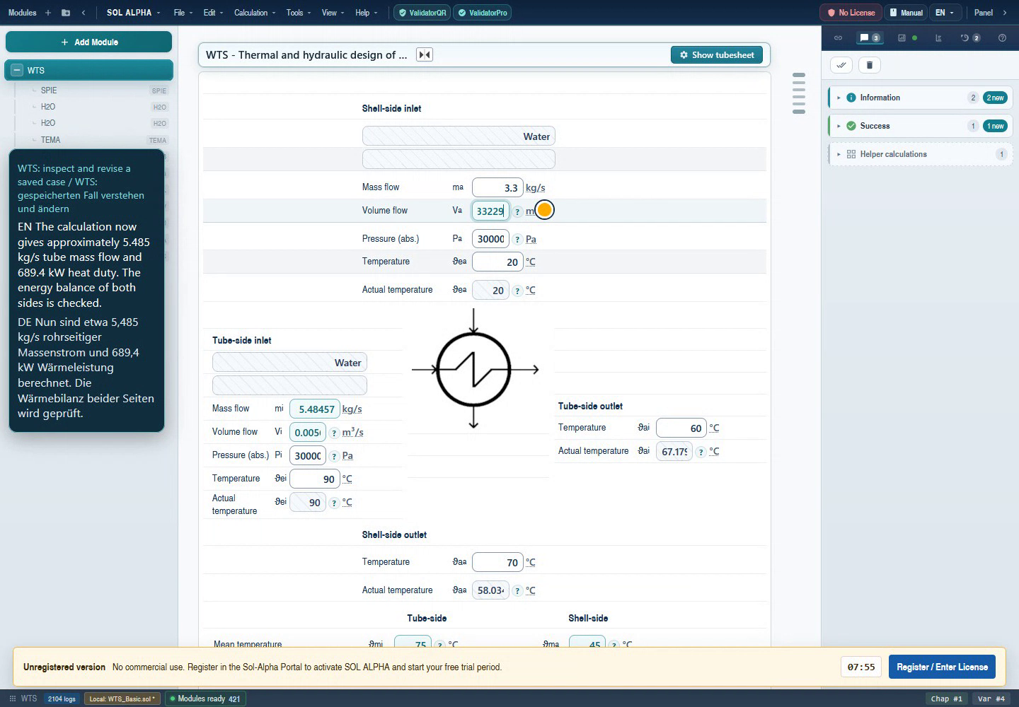
- V2 was the only input changed, to 3.3 kg/s.
- V1 follows from the duty at approximately 5.48457 kg/s.
- The actual outlet temperature still requires separate assessment.
Unaltered frame from the 6 September 2026 demo; English UI with the original bilingual video captions. Full-size original
Chapter 18Inverse calculation: deliberately releasing a constraint
Inverse calculation makes a previously calculated quantity a target and permits a suitable former input to become unknown. It can express a new geometry or process question. It does not guarantee a unique solution for every arbitrary combination.
Example: changing tube inside diameter
A smooth tube with 14 mm outside diameter and 1 mm wall has 12 mm inside diameter. If 11 mm inside is required, decide what remains fixed: keeping 14 mm outside requires 1.5 mm wall geometrically; keeping 1 mm wall requires 13 mm outside. Holding both original constraints while additionally requiring 11 mm inside is inconsistent.
- Save a copy and record tube selection, fixed state and connection of the affected field.
- If a standard-tube selection owns the geometry, change that selection preferentially. An explicit tube selection is more meaningful than forcing a contradiction into its derived fields.
- If free geometry input is supported, open the context menu of the quantity allowed to vary and use the offered release function.
- Enter the new target with a unit and confirm.
- Check the released result and the tube layout, count, area, velocity and pressure loss. A new outside diameter may not fit the old layout.
Example: a duty target instead of fixed throughput
When both temperature changes and one mass flow are specified, duty follows from the balance. To prescribe duty instead, a suitable quantity such as a mass flow must become free. Availability and convergence of this route depend on the actual equations and fluid configuration. Do not prescribe target duty, all temperatures and all mass flows as independent requirements simultaneously.
Back to top ↑Chapter 19Variants, parameter studies and connected calculations
A useful study answers one question
For example: “How do area and pressure loss change with higher shell throughput?” Keep geometry, composition, calculation edition and other duty requirements fixed. Vary only shell mass flow and record V1, V13/V14, V16/V17, V21, V23, V46, V64/V65 and V205. Allowing automatic layout changes defines a different study; also record tube count and shell dimensions in that case.
The general SOL ALPHA interface supports parameter variations. Input notation 1,2...3 belongs to the intended sequence/study function and must not be mistaken for a decimal number. In the offered study dialog, verify start, increment, end, unit and generated case count before calculating. Three individually saved variants are often easier for beginners to verify than a large series.
- Create a fully understood baseline.
- Select a genuine free input, not a child value managed by the parent.
- Define an engineering-valid range with a few steps.
- Run the study and inspect warnings and cancellations for individual points.
- Compare only completed, comparable cases. A blank value is neither zero nor automatically “same as previous”.
- Deliberately transfer a selected variant into its own project and review it completely.
Connections to other modules
A variable connection transfers an engineering relationship; it is not merely a convenient copy. Check source chapter, target chapter, quantity type, unit and intended direction. Bookmarks help locate a source variable and connect it to another module. Drag-and-drop and AutoConnect can simplify setup, but proposed mappings still need engineering review.
A documented WTS dimension can, for example, feed a separate mechanical assessment. Operating pressure is not automatically design pressure, and operating temperature is not automatically design temperature. Connecting similarly named fields must not conceal these distinctions. Do not overlay internal WTS children with contradictory parallel connections.
Making dependencies visible
The context action for highlighting dependent variables helps explain the consequences of a change. A connection colour indicates a relationship, not its engineering validity. If a target is immediately overwritten again, first inspect its connection and owning source. Disconnect only deliberately and after preserving the original state.
Back to top ↑Chapter 20Assessing results: area margin and calculation edition
The key result groups
- Heat balance
- V13/V14 together with V15 must match the duty. Read signs and units.
- Film and overall heat transfer
- V16/V17 describe each side; V23 combines the resistances. A high coefficient on one side can still be limited by the other side, the wall or fouling.
- Requirement and availability
- V21 and V46 are required quantities; V96 and V60 describe available area and active length. Their comparison is more useful than an isolated positive area value.
- Hydraulics and temperature achievement
- V64/V65, velocities and actual temperatures must also be acceptable.
Reading area margin correctly
For the ordinary area comparison, margin expresses available area in excess of required area:
110 m² available against 100 m² required gives +10%; 90 m² available gives −10%. Special routes can use a different area basis; the heated OhmEx route, for example, assigns heated area. Check the actual variable definition.
A margin change from 0.5% to 0.6% is 0.1 percentage points, but 20% relative to the small starting value. Automated comparison can flag this despite a small absolute margin change. Conversely, several percentage points can matter in a tight design. Record absolute and relative differences and do not apply one blanket tolerance to all quantities.
Selecting edition 11 or 12
The results section contains “Calculation according to 11th edition VDI Heat Atlas”. This is WTS variable V356: selected/1 means edition 11; cleared/0 means the newer edition-12 calculation in the inspected route. When the flag is unknown, the reviewed WTS source defaults it to 0. WTS passes this choice to GB. It is therefore not a display preference or a global switch for every equation in every module.
- Record the existing setting and save a comparison case.
- Change the visible edition option in WTS results.
- Wait for recalculation.
- Compare V16, V23, V21, V46 and V205 with otherwise identical requirements and layout.
- Record the edition in the result report.
An old archive value based on a different calculation approach is not a universal target for the new edition. Legitimate correlation changes must be distinguished from errors in geometry transfer, fluid state, fixed constraints or recalculation.
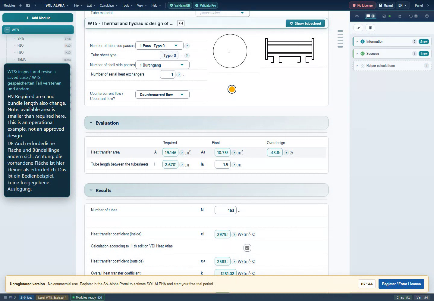
- Read required area, available area and negative margin together.
- Required length approximately 2.67 m; actual only 1.5 m.
- The edition-11 option is selected here. It affects the calculation route.
Unaltered frame from the 6 September 2026 demo; English UI with the original bilingual video captions. Full-size original
Chapter 22Saving, archive comparison and documentation
A dependable saved state
Save after all intended inputs are confirmed and required dialogs are completed. Name the variant after its duty, not simply “new”. Record fluids, operating case, geometry, edition and date in the project comment or accompanying report. Do not overwrite a historical original for a test.
The reopen check
- Record key values with units and states before saving.
- Save a new file and open it in a separate project state.
- Compare inputs, fluid parameters and layout first; results second.
- Check at least tube count, shell/tube dimensions, first/regular baffle spacings, active length, edition, duty, area and margin.
- If a discrepancy appears, preserve both states and the exact action. Do not obscure the original finding with further random edits.
Comparing old archives fairly
A saved result may originate from an earlier property basis, edition or incomplete historical calculation. Compare assumptions first. For margin, percentage points are often more informative than relative percentages. A new result with a plausible balance and consistent geometry may legitimately differ, but that alone does not explain the discrepancy. Document the specific cause.
Outputs and follow-on tasks
The WTS specification-sheet route contains Excel templates and language-dependent output paths. KUDO is separate customer documentation. WTSC is an additional WTS drawing/interface route. Output availability in Web and Desktop depends on integration, templates and entitlement. This handbook does not claim a successfully exercised export of every variant.
A result report should contain duty, data sources, software/module version, edition, geometry, heat balance, pressure losses, margin, relevant warnings and outstanding checks. Mechanical design to the required code is a separate task. This HTML can be printed through the browser; the maintained HTML remains the authoritative documentation version.
Back to top ↑Chapter 2320 common situations and what to check
1. After an input, results are missing.
You have started a case or changed a requirement. Check incomplete basic data, fluid states, required dialogs and contradictory fixed values. A blank value is unknown, not zero. Start with messages and the first missing intermediate result.
Read the relevant chapter →2. Why are there two water chapters?
Both sides can contain water at different states. Identify the parent and fluid side of each property child before comparing temperatures or properties.
Read the relevant chapter →3. An input immediately changes back.
The quantity may be managed by a connection, standard selection or parent module. Inspect its origin. Change the owning source or explicit input mode instead of repeatedly editing the dependent field.
Read the relevant chapter →4. What does a teal number mean?
The standard display distinguishes calculated values by colour. Also inspect state, unit and any connection. Colour is not engineering approval and can vary with theme or state.
Read the relevant chapter →5. Area is positive, but margin is negative.
A positive required area is normal. Negative margin in the ordinary area comparison means less is available than required. Compare V21 with V96 and V46 with V60.
Read the relevant chapter →6. Target and actual temperatures differ.
You may be comparing a process requirement with the capacity of specified geometry. Insufficient area cannot achieve the target. Check the available FN/ZELL route and balance.
Read the relevant chapter →7. Why do values change when the edition changes?
WTS option V356 is passed to the internal heat-transfer route. A changed coefficient changes k, requirement and margin. Compare with identical layout and inputs.
Read the relevant chapter →8. Can I fix both mass flows and all temperatures?
Only if the requirements are mutually consistent and the selected route allows it. Otherwise the balance is over-constrained. Decide which quantity should be a result.
Read the relevant chapter →9. Tube count changes after editing a tube dimension.
A new outside diameter or pitch can require a different layout. Check whether redesign was intended or an existing geometry should have remained frozen.
Read the relevant chapter →10. The first baffle distance does not stay as expected.
Distinguish V59 from V58 and inspect the special option, fixed state and geometry source. Preserve a reproducible before/after case if a confirmed requirement is overwritten despite the appropriate mode.
Read the relevant chapter →11. Why is a special command disabled?
The function may not apply to the construction or may be owned by a parent KOND/UVERD workflow. Check the owning parent and entitlement. Internal flags are not a substitute for the UI.
Read the relevant chapter →12. Must I create every child manually?
No. The normal WTS workflow requests the appropriate children itself. Manually added modules with the same name are not automatically the children managed by WTS.
Read the relevant chapter →13. May I enter alpha from a supplier document?
The explicit manual-input mode supports this. Check side, area basis, unit and operating state, and document the value as an external assumption.
Read the relevant chapter →14. Cold-start pressure loss is much higher.
Oils in particular can be much more viscous when cold. Check cold-start temperature and properties; do not compare blindly with warm steady operation.
Read the relevant chapter →15. Is vapour quality the same as relative humidity?
No. They are different state quantities. Read the field definition and select the appropriate pure-condensation or humid-gas route.
Read the relevant chapter →16. Why does a different heat-transfer child appear?
Tube form, phase, orientation or baffle construction may have changed. GG, GGO, GD and JA modules are not merely alternative names. Check the selected physical duty.
Read the relevant chapter →17. An archive differs strongly only in relative margin.
Relative differences are unstable for margin near zero. Compare percentage points and available/required area. Conversely, large percentage-point differences must not be dismissed as rounding.
Read the relevant chapter →18. The layout looks different after reopening.
Preserve the original and reopened state. Compare count, dimensions, lanes and library/frozen state before judging the drawing. Record format, version and exact save action.
Read the relevant chapter →19. A study contains individual blank points.
Individual states may be invalid, incomplete or cancelled. Inspect each affected case. Do not fill blank results with the previous valid result.
Read the relevant chapter →20. Is the design finished when margin is positive?
No. Check pressure losses, achieved temperatures, property/model limits, vibration and the separate mechanical design. Project-specific approval follows those checks.
Read the relevant chapter →Chapter 24Checklists for a traceable result review
A. Before calculating
- Duty and responsible data sources recorded.
- Tube/shell side, fluid, phase, concentration and pressure reference unambiguous.
- Design or rating selected; variable and fixed quantities identified.
- Materials, geometry, internals and relevant operating limits documented.
B. After calculating
- No required interaction pending; no unassessed errors or cancellations.
- Plausible heat balance, verified units and no unknown key results.
- WTS and its children use the same intended geometry and fluid states.
- Requirement, available area, margin and actual temperatures understood.
- Pressure-loss limits and velocities checked separately, including cold start.
- Model applicability and relevant vibration/material limits assessed.
C. Before issuing results
- Version, edition and external assumptions stated.
- Saved copy reopened and key quantities compared.
- Outstanding points explicitly recorded in the report, not just in a session.
- Required mechanical and project approvals distinguished from thermal calculation.
A useful issue report
Provide an anonymised demo file or authorised project data, exact module instance, variable, input with unit, previous fixed/connection state, expected effect, observed value, messages and software version. For recalculation defects, the exact action is often more useful than an end-result screenshot. Access keys and confidential customer data do not belong in public issue reports.
Back to top ↑Chapter 25Terms and symbols
- Film heat-transfer coefficient α
- Heat transfer between one fluid and the wall.
- Overall heat-transfer coefficient k
- Combined effect of both sides, the wall and included additional resistances; note the area basis.
- Fouling
- Additional thermal resistance from deposits. Record the assumed value and source.
- LMTD / ΔTlog
- Logarithmic mean temperature difference for the assumed flow arrangement.
- FN
- Temperature-arrangement correction in the corresponding WTS route.
- NTU
- Dimensionless transfer quantity; under the corresponding definition, kA divided by the smaller heat-capacity rate.
- Reynolds number Re
- Ratio of inertial to viscous effects; characteristic length depends on the model.
- Prandtl number Pr
- Ratio of momentum diffusivity to thermal diffusivity.
- Tube layout / tubesheet arrangement
- Tube arrangement including pass lanes and construction boundaries.
- Baffle
- Internal element guiding flow and supporting tubes.
- BEK / known state
- Internal known/origin state, not a physical value. Unknown is not zero.
- Konst / fixed state
- Identifies a fixed requirement in calculation state; distinct from known and connected.
- Child module
- Specialist module assigned to a parent chapter.
- Fixed point / recalculation
- Coupled updates until no further pending change remains or a failure is reported.
- Rating
- Performance assessment of specified geometry at defined operating conditions.
- Percentage point
- Absolute difference between two percentage values, not their relative change.
Chapter 26Directory of all fluid identifiers
Technical identifiers help with mapping and diagnostics. Select fluids through basic data, not by entering these numbers directly. Additional parameters and model limits still apply.
| ID | Fluid | Property module |
|---|---|---|
| 0 | Free input | SDAT |
| 1 | Water | H2O |
| 2 | Steam condensation | H2O |
| 3 | Natural gas L | EGAS |
| 4 | Natural gas H | EGAS |
| 5 | Air | LUFT |
| 6 | Ammonia | NH3 |
| 7 | Ammonia condensation | NH3 |
| 8 | Humid gas | HX |
| 9 | Proper | PROP |
| 10 | Legacy glycol | Legacy identifier; no active registry route |
| 11 | Thermal oil | TOIL |
| 12 | Flue gas | RGAS |
| 13 | Oil | OEL |
| 14 | Refrigerant | FRIG |
| 15 | Glycol / Antifrogen | GLYC |
| 16 | Nitrogen | N2 |
| 17 | STAB property selection | STAB |
| 18 | Sulfuric acid | H2SO |
| 19 | Nitric acid | HNO3 |
| 20 | Hydrochloric acid | HCL |
| 21 | Helium | HE |
| 22 | Sucrose | SAC |
| 23 | Carbon dioxide | CO2 |
| 24 | CO₂ condensation | CO2 |
| 25 | Gas mixture | N2H2 |
| 26 | Seawater | SAWA |
| 27 | Natural gas, free input | EGAS |
| 28 | Beer/wort | BIER |
| 29 | Sodium hydroxide | NAOH |
| 30 | Heavy fuel oil | HFO |
| 31 | Oxygen | O2 |
Chapter 27Complete WTS module inventory
The inventory contains 61 unique module identifiers: 50 literal references in the captured WTS files plus additional dynamic property routes. A match can be a conditional call, lookup of an existing chapter or special route. It does not establish live availability under your licence.
Back to top ↑Chapter 28WTS field reference V1–V360
This directory covers 349 named variables, including internal state identifiers. The remaining 11 identifiers are placeholders/reserved. Not every variable is visible or editable in every construction. A mask association only means an occurrence exists in the captured WTS mask; visibility, unit and input permissions are also determined at runtime.
Use search with, for example, “V205”, “vapour” or “tube”. Chapter links explain the corresponding group; they are not separate validity evidence for every internal helper quantity.
| ID | Name | In mask source | Explanation |
|---|---|---|---|
| V1 | Mass flow (inside) m_i | Yes; conditional | Chapter → |
| V2 | Mass flow outside m_a | Yes; conditional | Chapter → |
| V3 | Volume flow inside | Yes; conditional | Chapter → |
| V4 | Volume flow outside | Yes; conditional | Chapter → |
| V5 | Density tube side | Yes; conditional | Chapter → |
| V6 | Density shell side | Yes; conditional | Chapter → |
| V7 | Specific heat capacity tube side | Yes; conditional | Chapter → |
| V8 | Specific heat capacity shell side | Yes; conditional | Chapter → |
| V9 | Inlet temperature (inside) te_i | Yes; conditional | Chapter → |
| V10 | Outlet temperature (inside) ta_i | Yes; conditional | Chapter → |
| V11 | Inlet temperature (outside) te_a | Yes; conditional | Chapter → |
| V12 | Outlet temperature (outside) ta_a | Yes; conditional | Chapter → |
| V13 | Heat duty inside Q_i | Yes; conditional | Chapter → |
| V14 | Heat duty outside Q_o | Yes; conditional | Chapter → |
| V15 | Heat loss flux Q_v | Yes; conditional | Chapter → |
| V16 | Internal heat-transfer coefficient αᵢ | Yes; conditional | Chapter → |
| V17 | External heat-transfer coefficient αₐ | Yes; conditional | Chapter → |
| V18 | Thermal conductivity tube | Yes; conditional | Chapter → |
| V19 | Thickness of heat exchange area s | No occurrence | Chapter → |
| V20 | Fouling resistance Rf | Yes; conditional | Chapter → |
| V21 | Required heat transfer area A | Yes; conditional | Chapter → |
| V22 | Log. mean temperature difference (LMTD) | Yes; conditional | Chapter → |
| V23 | Overall heat transfer coefficient k | Yes; conditional | Chapter → |
| V24 | Outside tube diameter | Yes; conditional | Chapter → |
| V25 | Inside tube diameter | Yes; conditional | Chapter → |
| V26 | Countercurrent flow = 0, Cocurrent flow = 1 | Yes; conditional | Chapter → |
| V27 | Auxiliary variable for co-current flow | No occurrence | Chapter → |
| V29 | Mean calculation temperature inside | Yes; conditional | Chapter → |
| V30 | Mean calculation temperature outside | Yes; conditional | Chapter → |
| V31 | mean wall temperature inside | Yes; conditional | Chapter → |
| V32 | mean wall temperature outside | Yes; conditional | Chapter → |
| V33 | Enthalpy of evaporation (inside) | Yes; conditional | Chapter → |
| V34 | Latent heat of vaporisation, shell side | Yes; conditional | Chapter → |
| V35 | Vapour fraction inlet inside | Yes; conditional | Chapter → |
| V36 | Vapour fraction inlet outside | Yes; conditional | Chapter → |
| V37 | Property inside | No occurrence | Chapter → |
| V38 | Property outside | No occurrence | Chapter → |
| V39 | Inlet pressure inside | Yes; conditional | Chapter → |
| V40 | Inlet pressure outside | Yes; conditional | Chapter → |
| V41 | Shell outside diameter | Yes; conditional | Chapter → |
| V42 | Shell wall thickness | Yes; conditional | Chapter → |
| V43 | Tube pitch crosswise to direction of flow | Yes; conditional | Chapter → |
| V44 | Tube pitch in direction of flow | Yes; conditional | Chapter → |
| V45 | Tube lane width b | Yes; conditional | Chapter → |
| V46 | Required bundle length l | Yes; conditional | Chapter → |
| V47 | Total number of tubes R | Yes; conditional | Chapter → |
| V48 | Property inside | No occurrence | Chapter → |
| V49 | Property outside | No occurrence | Chapter → |
| V50 | Alpha inside | No occurrence | Chapter → |
| V51 | New design of tubesheet | No occurrence | Chapter → |
| V52 | Tubesheet | No occurrence | Chapter → |
| V53 | Fluid velocity in the tubes | Yes; conditional | Chapter → |
| V54 | shell diameter (inside) | Yes; conditional | Chapter → |
| V55 | Number of tube-side passes | Yes; conditional | Chapter → |
| V56 | Baffle cut | Yes; conditional | Chapter → |
| V57 | Bundle-shell distance | Yes; conditional | Chapter → |
| V58 | Baffle spacing | Yes; conditional | Chapter → |
| V59 | Distance between tubesheet and 1st baffle | Yes; conditional | Chapter → |
| V60 | Actual length of bundle | Yes; conditional | Chapter → |
| V61 | Desired tube-side velocity | No occurrence | Chapter → |
| V62 | Desired shell-side velocity | No occurrence | Chapter → |
| V63 | Minimum baffle pitch | No occurrence | Chapter → |
| V64 | Pressure drop tube side | Yes; conditional | Chapter → |
| V65 | Pressure drop shell side | Yes; conditional | Chapter → |
| V66 | Vapour velocity tube side | No occurrence | Chapter → |
| V67 | Density of vapour (inside) | Yes; conditional | Chapter → |
| V68 | Vapour velocity | No occurrence | Chapter → |
| V69 | Density of vapour outside | Yes; conditional | Chapter → |
| V70 | Inside diameter of inlet nozzle tube side | Yes; conditional | Chapter → |
| V71 | Inside diameter of outlet nozzle tube side | Yes; conditional | Chapter → |
| V72 | Inside diameter inlet nozzle shell side | Yes; conditional | Chapter → |
| V73 | Inside diameter of outlet nozzle shell side | Yes; conditional | Chapter → |
| V74 | Velocity inlet tube side | Yes; conditional | Chapter → |
| V75 | Velocity outlet tube side | Yes; conditional | Chapter → |
| V76 | Velocity inlet shell side | Yes; conditional | Chapter → |
| V77 | Velocity outlet shell side | Yes; conditional | Chapter → |
| V78 | TEMA Flag | No occurrence | Chapter → |
| V79 | Proper Flag | No occurrence | Chapter → |
| V80 | FN Factor | Yes; conditional | Chapter → |
| V81 | Allowable steam superheat at condensation | Yes; conditional | Chapter → |
| V82 | Flag tubesheet designed | No occurrence | Chapter → |
| V83 | Flow direction | No occurrence | Chapter → |
| V84 | Thermal conductivity medium inside | Yes; conditional | Chapter → |
| V85 | Dynamic viscosity, tube side | Yes; conditional | Chapter → |
| V86 | Thermal conductivity shell side | Yes; conditional | Chapter → |
| V87 | Dynamic viscosity (outside) | Yes; conditional | Chapter → |
| V89 | Number of heat exchangers in series | Yes; conditional | Chapter → |
| V90 | Calculation according to TEMA | No occurrence | Chapter → |
| V91 | Fouling resistance f tube side | Yes; conditional | Chapter → |
| V92 | Fouling resistance f shell side | Yes; conditional | Chapter → |
| V93 | Pitch angle | Yes; conditional | Chapter → |
| V94 | Fluid velocity shell side | Yes; conditional | Chapter → |
| V95 | Temperature differential of transf. Coefficient | No occurrence | Chapter → |
| V96 | Actual exchanger area A | Yes; conditional | Chapter → |
| V97 | Number of shell-side passes | Yes; conditional | Chapter → |
| V98 | Number of tubes old | No occurrence | Chapter → |
| V99 | Frost resistance (Glycol tube-side) | No occurrence | Chapter → |
| V100 | Prandtl wall inside | No occurrence | Chapter → |
| V101 | Prandtl wall outside | No occurrence | Chapter → |
| V102 | Eta wall inside | No occurrence | Chapter → |
| V103 | Eta wall outside | No occurrence | Chapter → |
| V104 | Minimum bundle-shell distance | Yes; conditional | Chapter → |
| V105 | Desired cut | No occurrence | Chapter → |
| V107 | Kind of medium inside | Yes; conditional | Chapter → |
| V108 | Kind of medium outside | Yes; conditional | Chapter → |
| V109 | Bore diameter in baffle | Yes; conditional | Chapter → |
| V110 | Adaption borehole in the baffle to TEMA | No occurrence | Chapter → |
| V111 | Maximum tube length | No occurrence | Chapter → |
| V112 | Maximum ratio l/Di | No occurrence | Chapter → |
| V113 | Minimum ratio l/Di | No occurrence | Chapter → |
| V114 | Adaption geometry (Design criteria) | No occurrence | Chapter → |
| V115 | Number of baffles per pass | Yes; conditional | Chapter → |
| V116 | Flag Joule-Thomson in the tubes | No occurrence | Chapter → |
| V117 | Baffle diameter | Yes; conditional | Chapter → |
| V118 | Number of sealing strip pairs | Yes; conditional | Chapter → |
| V119 | Fin diameter | Yes; conditional | Chapter → |
| V120 | Fin pitch | Yes; conditional | Chapter → |
| V121 | Fin thickness | Yes; conditional | Chapter → |
| V122 | Flag low finned tubes | No occurrence | Chapter → |
| V123 | Exchanger area inside | No occurrence | Chapter → |
| V124 | Baffle arrangement (internal selection identifier) | No occurrence | Chapter → |
| V125 | Product of (area x heat transfer) | No occurrence | Chapter → |
| V126 | Property module 1 (inside) | No occurrence | Chapter → |
| V127 | Property module 2 (inside) | No occurrence | Chapter → |
| V128 | Property module 3 (inside) | No occurrence | Chapter → |
| V129 | Property module 1 (outside) | No occurrence | Chapter → |
| V130 | Property module 2 (outside) | No occurrence | Chapter → |
| V131 | Property module 3 (outside) | No occurrence | Chapter → |
| V132 | Frost resistance (Glycol shell-side) | No occurrence | Chapter → |
| V133 | First-baffle-spacing prescription rule | No occurrence | Chapter → |
| V134 | Call RBSA Module | No occurrence | Chapter → |
| V135 | Bundle type | Yes; conditional | Chapter → |
| V136 | Diameter of bundle (KWU-exchanger) | No occurrence | Chapter → |
| V137 | Fluid velocity in first tube row | No occurrence | Chapter → |
| V138 | Flag for fittings in the tubes | No occurrence | Chapter → |
| V139 | Flag for fins in the tubes | No occurrence | Chapter → |
| V140 | Number of fins/tube (internal fin) | Yes; conditional | Chapter → |
| V141 | Fin height (internal fin) | Yes; conditional | Chapter → |
| V142 | Fin thickness at fin tip (internal fin) | Yes; conditional | Chapter → |
| V143 | Fin thickness at fin root (internal fin) | Yes; conditional | Chapter → |
| V144 | Flag for standard value | No occurrence | Chapter → |
| V145 | Internal helper identifier for equation 28 | No occurrence | Chapter → |
| V146 | Flag for ´WTSELECT´ | No occurrence | Chapter → |
| V147 | Flag for locked tubesheet | No occurrence | Chapter → |
| V148 | Property module 4 (inside) | No occurrence | Chapter → |
| V149 | Property module 4 (outside) | No occurrence | Chapter → |
| V151 | Name of medium inside for PROPER | No occurrence | Chapter → |
| V152 | Name of medium outside for PROPER | No occurrence | Chapter → |
| V153 | Flag for lengthwise-finned tubes | No occurrence | Chapter → |
| V154 | Number of fins per tube | No occurrence | Chapter → |
| V155 | Fin height | No occurrence | Chapter → |
| V156 | Fin thickness at fin root | No occurrence | Chapter → |
| V157 | Thermal conductivity of the fins | Yes; conditional | Chapter → |
| V158 | Density of tube-side fluid at wall temperature | No occurrence | Chapter → |
| V159 | Tube outside area for one tube with a length of 1 m | No occurrence | Chapter → |
| V160 | Tube inside area for one tube with a length of 1 m | No occurrence | Chapter → |
| V161 | Density of shell-side fluid at wall temperature | No occurrence | Chapter → |
| V162 | Pointer liquid/vapour (for GGLR) | No occurrence | Chapter → |
| V163 | Flag for double pipe | No occurrence | Chapter → |
| V165 | Disk diameter | No occurrence | Chapter → |
| V166 | Diameter doughnut | No occurrence | Chapter → |
| V167 | Helix angle | Yes; conditional | Chapter → |
| V168 | Fin diameter | No occurrence | Chapter → |
| V169 | Set alpha inside? <Yes = 1 or No = 0> | No occurrence | Chapter → |
| V170 | Set alpha outside? <Yes = 1 or No = 0> | No occurrence | Chapter → |
| V171 | Flag for lamellar block 1 = lamellas | No occurrence | Chapter → |
| V172 | Adapt distance tubesheet - 1st baffle | No occurrence | Chapter → |
| V173 | Phase inside: ,liquid = 0, gas = 1, cond = 2 | No occurrence | Chapter → |
| V174 | Phase outside: liquid = 0, gas = 1, cond = 2 | No occurrence | Chapter → |
| V175 | Corrugated-tube flag | No occurrence | Chapter → |
| V176 | Medium inside; detailed name | Yes; conditional | Chapter → |
| V177 | Medium outside; detailed name | Yes; conditional | Chapter → |
| V178 | Geometry description tube-side | Yes; conditional | Chapter → |
| V179 | Geometry description shell-side | Yes; conditional | Chapter → |
| V180 | Real temperature inlet medium inside | Yes; conditional | Chapter → |
| V181 | Real temperature inlet medium outside | Yes; conditional | Chapter → |
| V182 | Flag simulate outlet temperature | No occurrence | Chapter → |
| V183 | Window velocity | Yes; conditional | Chapter → |
| V184 | Shell-material identifier for ETS special route | No occurrence | Chapter → |
| V185 | Standard density gas shell side | Yes; conditional | Chapter → |
| V186 | Standard density gas tube side | Yes; conditional | Chapter → |
| V187 | Standard volume flow shell sideV_N_a | Yes; conditional | Chapter → |
| V188 | Standard volume flow tube side V_N_i | Yes; conditional | Chapter → |
| V189 | Calling KOND/UVERD parent chapter index | No occurrence | Chapter → |
| V190 | Shell-selected flag | No occurrence | Chapter → |
| V191 | Installation position | Yes; conditional | Chapter → |
| V192 | Extra flag for tubesheet | No occurrence | Chapter → |
| V193 | Correction factor for alpha tubeside | No occurrence | Chapter → |
| V194 | Silage type for FUOSO special route | No occurrence | Chapter → |
| V195 | BEHR woven-bundle flag | No occurrence | Chapter → |
| V196 | Total tube length (incl. tubesheet) | No occurrence | Chapter → |
| V197 | Tube-side property-module variant identifier | No occurrence | Chapter → |
| V198 | Shell-side property-module variant identifier | No occurrence | Chapter → |
| V199 | Name of type in library | Yes; conditional | Chapter → |
| V200 | Flag: No tubes in window | Yes; conditional | Chapter → |
| V201 | Fw correction factor thermal conductivity longitudinal baffle | No occurrence | Chapter → |
| V202 | Universal Hydraulik special-route flag | No occurrence | Chapter → |
| V203 | Number of tube rows in the cross flow zone | No occurrence | Chapter → |
| V204 | Baffle cut | No occurrence | Chapter → |
| V205 | Area margin / overdesign | Yes; conditional | Chapter → |
| V206 | WTSC call flag | No occurrence | Chapter → |
| V207 | Baffle type | Yes; conditional | Chapter → |
| V208 | Inside temperature at start-up | No occurrence | Chapter → |
| V209 | Outside temperature at start-up | No occurrence | Chapter → |
| V210 | Density medium inside at start-up temperature | No occurrence | Chapter → |
| V211 | Density medium outside at start-up temperature | No occurrence | Chapter → |
| V212 | Spec. heat capacity medium inside at start-up temperature | No occurrence | Chapter → |
| V213 | Spec. heat capacity medium outside at start-up temperature | No occurrence | Chapter → |
| V214 | Dyn. viscosity Medium medium inside at start-up temperature | No occurrence | Chapter → |
| V215 | Dyn. Viscosity medium outside at start-up temperature | No occurrence | Chapter → |
| V216 | Thermal conductivity medium inside at start-up temperature | No occurrence | Chapter → |
| V217 | Thermal conductivity medium outside at start-up temperature | No occurrence | Chapter → |
| V218 | Inside pressure drop at start-up temperature | No occurrence | Chapter → |
| V219 | Outside pressure drop at start-up temperature | No occurrence | Chapter → |
| V220 | NewCool flag | No occurrence | Chapter → |
| V221 | Siemens condenser flag | No occurrence | Chapter → |
| V222 | Number of holes | No occurrence | Chapter → |
| V223 | Actual tube-side outlet temperature | Yes; conditional | Chapter → |
| V224 | Actual shell-side outlet temperature | Yes; conditional | Chapter → |
| V225 | Internal visualisation-completed flag | No occurrence | Chapter → |
| V226 | Salinity tube-side | No occurrence | Chapter → |
| V227 | Salinity shell-side | No occurrence | Chapter → |
| V228 | Vertical pass-lane width | Yes; conditional | Chapter → |
| V229 | Enthalpy inside inlet | No occurrence | Chapter → |
| V230 | Tube-side outlet enthalpy | No occurrence | Chapter → |
| V231 | Enthalpy outside inlet | No occurrence | Chapter → |
| V232 | Enthalpy outside outlet | No occurrence | Chapter → |
| V233 | Enthalpy h' inside | No occurrence | Chapter → |
| V234 | Enthalpy h'' inside | No occurrence | Chapter → |
| V235 | Enthalpy h' outside | No occurrence | Chapter → |
| V236 | Enthalpy h'' outside | No occurrence | Chapter → |
| V237 | Boiling temperature inside | No occurrence | Chapter → |
| V238 | Boiling pressure inside | No occurrence | Chapter → |
| V239 | Boiling temperature outside | No occurrence | Chapter → |
| V240 | Boiling pressure outside | No occurrence | Chapter → |
| V241 | Vapour fraction outlet inside | Yes; conditional | Chapter → |
| V242 | Vapour fraction outlet outside | Yes; conditional | Chapter → |
| V243 | Rho · v² inside inlet | No occurrence | Chapter → |
| V244 | Rho · v² inlet nozzle shell side | Yes; conditional | Chapter → |
| V245 | Thickness longitudinal baffle | No occurrence | Chapter → |
| V246 | Thermal conductivity longitudinal baffle | No occurrence | Chapter → |
| V247 | Longitudinal baffle length | No occurrence | Chapter → |
| V248 | Velocity around the disk | No occurrence | Chapter → |
| V249 | Velocity in opening of doughnut | No occurrence | Chapter → |
| V250 | Tubesheet type | Yes; conditional | Chapter → |
| V251 | Mass flow condensate humid gas inside | Yes; conditional | Chapter → |
| V252 | Mass flow condensate humid gas outside | Yes; conditional | Chapter → |
| V253 | Bundle type | No occurrence | Chapter → |
| V254 | OhmEx flag | No occurrence | Chapter → |
| V255 | Maximum film temperature | No occurrence | Chapter → |
| V256 | Max. wall temperature | No occurrence | Chapter → |
| V257 | Heat flux | No occurrence | Chapter → |
| V258 | Difference max. film temperature - max. wall temperature | No occurrence | Chapter → |
| V259 | Heated tube length | No occurrence | Chapter → |
| V260 | Heated area | No occurrence | Chapter → |
| V261 | Flag: No tubes around disk | No occurrence | Chapter → |
| V262 | Flag: No tubes in doughnut | No occurrence | Chapter → |
| V263 | Modulus of elasticity | No occurrence | Chapter → |
| V264 | Effective density | No occurrence | Chapter → |
| V265 | Redimensioning | No occurrence | Chapter → |
| V266 | Flow type: Cocurrent / Countercurrent | Yes; conditional | Chapter → |
| V267 | No-tubes-in-window | Yes; conditional | Chapter → |
| V268 | Emission ratio tubes | No occurrence | Chapter → |
| V269 | Emission ratio shell | No occurrence | Chapter → |
| V270 | Maximum temperature of shell | No occurrence | Chapter → |
| V271 | Density of shell-side medium at outlet | No occurrence | Chapter → |
| V272 | Specific heat capacity of shell-side medium at outlet | No occurrence | Chapter → |
| V273 | Thermal conductivity of shell-side medium at outlet | No occurrence | Chapter → |
| V274 | Dyn. Viscosity of shell-side medium at outlet | No occurrence | Chapter → |
| V275 | Prandtl number of shell-side medium at outlet | No occurrence | Chapter → |
| V276 | Heat transfer coefficient k shell-side at outlet | No occurrence | Chapter → |
| V277 | Boiling temperature internal pressure | No occurrence | Chapter → |
| V278 | Boiling temperature external pressure | No occurrence | Chapter → |
| V279 | Dietzel flag | No occurrence | Chapter → |
| V280 | HSCooler flag | No occurrence | Chapter → |
| V281 | Minimal distance between tubesheet and 1st baffle | No occurrence | Chapter → |
| V282 | Area margin from HS-Cooler | No occurrence | Chapter → |
| V283 | Re inside | Yes; conditional | Chapter → |
| V284 | Re outside | Yes; conditional | Chapter → |
| V285 | Tube material | Yes; conditional | Chapter → |
| V286 | Nominal diameter inlet nozzle tube side | Yes; conditional | Chapter → |
| V287 | Nominal diameter outlet nozzle tube side | Yes; conditional | Chapter → |
| V288 | Nominal diameter inlet nozzle shell side | Yes; conditional | Chapter → |
| V289 | Nominal diameter outlet nozzle shell side | Yes; conditional | Chapter → |
| V290 | Outside diameter inlet nozzle tube side | Yes; conditional | Chapter → |
| V291 | Outside diameter outlet nozzle tube side | Yes; conditional | Chapter → |
| V292 | Outside diameter inlet nozzle shell side | Yes; conditional | Chapter → |
| V293 | Outside diameter outlet nozzle shell side | Yes; conditional | Chapter → |
| V294 | Beer/wort selection, tube side | No occurrence | Chapter → |
| V295 | Beer/wort selection, shell side | No occurrence | Chapter → |
| V296 | KOND subcooling route: flooded/falling film | No occurrence | Chapter → |
| V297 | Crit. pressure inside | No occurrence | Chapter → |
| V298 | Crit. pressure outside | No occurrence | Chapter → |
| V299 | Critical temperature inside | No occurrence | Chapter → |
| V300 | Critical temperature outside | No occurrence | Chapter → |
| V301 | Dyn. viscosity vapour inside (condensation) | Yes; conditional | Chapter → |
| V302 | Dynamic viscosity steam outside condensation | Yes; conditional | Chapter → |
| V303 | Surface tension inside | No occurrence | Chapter → |
| V304 | Surface tension outside | No occurrence | Chapter → |
| V305 | Tube wall thickness | Yes; conditional | Chapter → |
| V306 | Striko flag | No occurrence | Chapter → |
| V307 | frictional heat Q_R | Yes; conditional | Chapter → |
| V308 | Specific heat capacity steam inside condensation | Yes; conditional | Chapter → |
| V309 | Specific heat capacity steam outside condensation | Yes; conditional | Chapter → |
| V310 | Thermal conductivity steam inside condensation | Yes; conditional | Chapter → |
| V311 | Thermal conductivity vapour outside (condensation) | Yes; conditional | Chapter → |
| V312 | Condensation wall-temperature-below-saturation flag | No occurrence | Chapter → |
| V313 | Desuperheating performance cond | No occurrence | Chapter → |
| V314 | Thickness baffles | Yes; conditional | Chapter → |
| V315 | Call GVLV module | No occurrence | Chapter → |
| V316 | Linear thermal expansion coefficient tube | No occurrence | Chapter → |
| V317 | Linear thermal expansion coefficient shell | No occurrence | Chapter → |
| V318 | Nozzle arrangement: none/same side/opposite | No occurrence | Chapter → |
| V319 | Total power Q_tot | No occurrence | Chapter → |
| V320 | Default outlet-vapour-quality flag | No occurrence | Chapter → |
| V321 | Number of U tubes | Yes; conditional | Chapter → |
| V322 | Volume flow inside out | No occurrence | Chapter → |
| V323 | Volume flow outside out | No occurrence | Chapter → |
| V324 | Log. mean temperature difference (corrected) CLMTD | Yes; conditional | Chapter → |
| V325 | Tube-layout pass-count-changed flag | No occurrence | Chapter → |
| V326 | Flag safety heat exchanger 0=no, 1=safety heat exchanger | No occurrence | Chapter → |
| V327 | Inside diameter outside tube safety heat exchanger | Yes; conditional | Chapter → |
| V328 | Outside diameter inside tube safety heat exchanger | Yes; conditional | Chapter → |
| V329 | Tube wall thickness inside tube safety heat exchanger | Yes; conditional | Chapter → |
| V330 | Thermal conductivity sealing liquid | Yes; conditional | Chapter → |
| V331 | Equivalent thermal conductivity safety heat exchanger | Yes; conditional | Chapter → |
| V332 | Distance from the last baffle to U bend | Yes; conditional | Chapter → |
| V333 | Length of helical baffle L | No occurrence | Chapter → |
| V334 | Thickness helical baffle t | No occurrence | Chapter → |
| V335 | Helical angle phi | No occurrence | Chapter → |
| V336 | Number of spiral cycles | No occurrence | Chapter → |
| V337 | Distance of hellical cycles | No occurrence | Chapter → |
| V338 | Diameter of center tube | No occurrence | Chapter → |
| V339 | Nozzle arrangment | No occurrence | Chapter → |
| V341 | Diameter supporting grids horizontal | No occurrence | Chapter → |
| V342 | Diameter supporting grids vertical | No occurrence | Chapter → |
| V343 | Outside diameter fixation ring | No occurrence | Chapter → |
| V344 | Inside diameter fixation ring | No occurrence | Chapter → |
| V345 | Relative humidity, tube side | Yes; conditional | Chapter → |
| V346 | Relative humidity, shell side | Yes; conditional | Chapter → |
| V350 | Outer-tube thermal conductivity | Yes; conditional | Chapter → |
| V351 | Contact thermal conductivity | Yes; conditional | Chapter → |
| V352 | Inner-tube contact area per metre of tube | Yes; conditional | Chapter → |
| V353 | Tube selection | Yes; conditional | Chapter → |
| V354 | Shell selection | Yes; conditional | Chapter → |
| V355 | Minimum bend radius | Yes; conditional | Chapter → |
| V356 | Calculate using edition 11 (1 = 11; 0 = 12 in the GB route) | Yes; conditional | Chapter → |
| V357 | Excel export flag | No occurrence | Chapter → |
| V358 | File-format identifier | No occurrence | Chapter → |
Chapter 29Sources, evidence limits and handbook maintenance
This handbook combines a review of the available source version, existing demonstration recordings and independently written engineering explanations. It does not replace the complete equations and applicability limits in the underlying technical literature.
Technical version
Web: fix-iteration/main13.0 @ 33e53dbff. All-Dev: fix-iteration/v10 @ 40606b705. Full commit IDs and captured source-file checksums are in the source inventory. Principal sources are WTS.Equations.vb, WTS.Connections.vb, KAPWTS.vb, KAPWTS.Extern.vb, WTS.Properties.Id.vb, WTS.MediaIds.vb, WTS language resources and WTS-1.json. Fluid routing is cross-checked against GetMediumTokenByIndex in KAPWAERME.vb.
What is supported by which evidence?
- Source review: Menu functions, fluid mappings, variable identifiers and conditional child calls. This does not establish live acceptance of every special construction.
- Demonstration evidence: Seven original images or unaltered frames of existing program output. Video recordings date from 6 September 2026. The separate basic-data image has no independently documented capture time.
- No new live calculation: A running local API was not available after the build for this handbook edition. Teaching-example values come from documented earlier checks.
- Fix evidence: The internal completion report describes 28/28 synthetic cases, 169/169 fixture cases and 239/240 completed archive runs. These are identified here as previously documented results, not tests rerun during handbook authoring. They do not establish complete parity for every WTS configuration.
Public manufacturer references
The general product purpose is explained by the LV WTS product description. The SPIE product page explains tube-layout calculation. Distinguish the separate VERD package for evaporators. For actual correlations and validity ranges, consult the edition of VDI Heat Atlas/HEDH or original references specified by the relevant module.
Maintain HTML instead of a separate PDF
Chapters, translations, figure legends and reference processing are separate from generated HTML. The handbook can therefore be redesigned without losing content or image provenance. Changes to equations, masks or module routes require an engineering review of the affected chapters. The technical snapshot is updated deliberately, not silently when opening a page. All necessary text and images are local; only optional manufacturer links and the existing video require Internet access.
Back to top ↑