Engineering task and calculation objective
Every nozzle, every manhole and every other opening weakens the pressure-loaded wall of a vessel: the pressure-loaded area stays the same, the load-bearing cross-section becomes smaller, and stress peaks arise at the edge of the opening. If you want to calculate openings and nozzles to AD 2000 — the German pressure vessel code — you perform the reinforcement verification to AD 2000-Merkblatt B9, for cylindrical, conical and spherical shells including dished ends (torispherical, semi-ellipsoidal and hemispherical ends).
The B9 module implements Merkblatt B9 in full. It handles single openings as well as adjacent openings whose reinforcement zones influence each other. The basis is the pressure-area method: the pressure-loaded areas are compared with the stress-loaded cross-sectional areas of shell, nozzle and, where applicable, reinforcing plate; within the effective lengths, set-on, set-in and set-through nozzles as well as extruded openings and block flanges may be credited.
In practice, this verification decides nozzle wall thicknesses, reinforcing plates and minimum distances between openings — it is part of the design of almost every apparatus with connection nozzles. The module reports the utilization and shows whether and how an opening must be additionally reinforced.
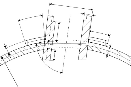
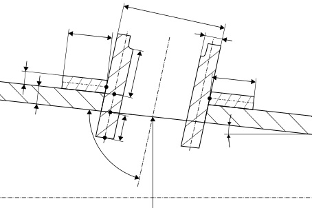
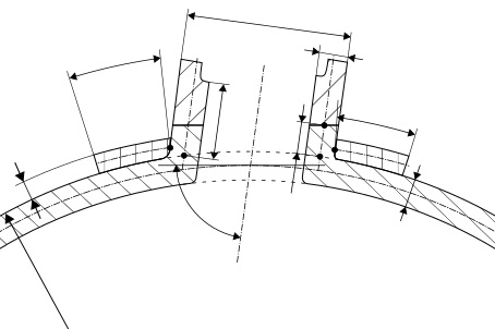
Standard and calculation basis: AD 2000 B9: 2023-03
Calculation scope
- Adjacent openings in cylindrical, conical and spherical shells
- Single openings in cylindrical, conical and spherical shells
Calculation workflow
- Define the base shell and the opening situation: First, the shell form (cylinder, cone, sphere or dished end), diameter, as-built wall thickness and the allowances are defined. Then the opening is described: single opening or adjacent openings, orientation (longitudinal, circumferential, oblique), diameter and nozzle configuration (set-on, set-in, set-through, extruded, block flange).
- Determine the effective lengths: For the base shell and the nozzle, the effective lengths are calculated within which material may be credited as reinforcement; for the nozzle, a creditable internal protrusion also counts. Reinforcing plates are taken into account with their width and thickness within the effective length.
- Compare pressure areas and cross-sectional areas: Following the pressure-area method, the pressure-loaded areas and the stress-loaded cross-sectional areas of shell, nozzle and reinforcement are determined. The strength condition links both area ratios with the allowable stress K/S of the materials involved; nozzle materials of lower strength are credited only proportionally.
- Check adjacent openings: If two openings lie so close together that their effective zones overlap, the ligament between the openings is verified separately; in the circumferential direction, different conditions apply than in the longitudinal direction because the membrane stress is halved. The module covers both directions as well as oblique arrangements.
- Evaluate the utilization and define the reinforcement: The module reports the utilization of the verification. If it is exceeded, reinforcement can be applied iteratively: a thicker nozzle, a reinforcing plate, a locally thicker shell or a larger opening spacing — until the strength condition is satisfied.
Input quantities
| Quantity | Symbol | Unit |
|---|---|---|
| Design pressure | p | bar |
| K | K | N/mm² |
| KS1 | K | N/mm² |
| KS2 | K | N/mm² |
| S | S | - |
| c1 | c1 | mm |
| c2 | c2 | mm |
| Corroded inside diameter | Di | mm |
| Design width | b1 | mm |
| Final thickness of reinforcement | hR1 | mm |
| Final wall thickness | se | mm |
| Ligament (web) between two nozzles | l | mm |
| Inward protruding length | m1 | mm |
| Inward protruding length | m2 | mm |
| Corroded inside diameter | di,1 | mm |
| Corroded inside diameter | di,2 | mm |
| Design temperature | T | °C |
| Schale | Schale | – |
| S1 | S1 | – |
| S2 | S2 | – |
| Outside diameter | Da | mm |
| c1,S1 | c1 | mm |
| c2,S1 | c2 | mm |
| c1,S2 | c1 | mm |
Calculated results
| Quantity | Symbol | Unit |
|---|---|---|
| Wall thickness at opening edge | sA,1 | mm |
| Design width | b1 | mm |
| Wall thickness ratio | sS1/sA | - |
| Wall thickness ratio | sS2/sA | - |
| Wall thickness at opening edge | sA,2 | mm |
| Minimum ligament without mutual influence | lmin,1 | mm |
| Minimum ligament without mutual influence | lmin,2 | mm |
| Design width | b2 | mm |
| Equivalent diameter of cylinder (AD 2000 B2) | Di,cone,1 | mm |
| Equivalent diameter of cylinder (AD 2000 B2) | Di,cone,2 | mm |
| Length of nozzle contributing to the reinforcement, longitudinal | lS1,max | mm |
| Length of nozzle contributing to the reinforcement, longitudinal | lS2,max | mm |
| Length of nozzle contributing to the reinforcement for sphere / circumference | lS1,max,circ | mm |
| Length of nozzle contributing to the reinforcement for sphere / circumference | lS2,max,circ | mm |
| Fictitious wall thickness of block flange | sfict,S1 | mm |
| Fictitious wall thickness of block flange | sfict,S2 | mm |
| Factor for necked-out nozzles | fred,S1 | – |
| Factor for necked-out nozzles | fred,S2 | – |
| UI,S1 | UI | % |
| UI,S2 | UI | % |
| UII,S1 | UII | % |
| UII,S2 | UII | % |
| Ucirc,S1 | Ucirc | % |
| Ucirc,S2 | Ucirc | % |
Calculation options
ATLVersion
Old · New
Lastfall
Operation · Testing · Exception
S1
No · Yes
S2
No · Yes
1
Opening · Set-on block flange · Set-in block flange · Necked-out opening · Set-on nozzle · Set-in nozzle · Set-through nozzle
2
Opening · Set-on block flange · Set-in block flange · Necked-out opening · Set-on nozzle · Set-in nozzle · Set-through nozzle
S1
Vertical · Longitudinal · Circumferrential · Both directions
S2
Vertical · Longitudinal · Circumferrential · Both directions
Frequently asked questions
When is an opening considered sufficiently reinforced without additional measures?
When the existing shell and nozzle wall thickness within the effective lengths provides enough stress-loaded area to satisfy the pressure-area balance. Small openings in generously dimensioned shells often pass the verification without reinforcement; the Merkblatt also defines limits below which single openings are uncritical. The calculated verification provides clarity here.
From what point are two openings considered adjacent?
If the distance between the opening edges is smaller than the sum of the effective lengths of both openings, the reinforcement zones overlap and the intermediate ligament must carry the loads of both openings. The verification for adjacent openings must then be performed — separately for the longitudinal and circumferential directions, since the membrane stresses in a cylinder are direction-dependent.
May a nozzle made of a lower-strength material be fully credited?
No. If the nozzle material has a lower nominal design stress than the base shell, its cross-section is credited only in proportion to the allowable stresses. Conversely, a stronger nozzle material provides no bonus beyond the shell strength — a common misconception with mixed material pairings.
What must be considered with reinforcing plates?
Reinforcing plates are effective only if they fit snugly and lie within the effective length; their creditable thickness and width are limited. At higher temperatures and under severe thermal cycling they are unfavorable because of the thermal stresses between plate and shell — in such cases thicker nozzles or extruded openings are the better reinforcement.