Engineering task and calculation objective
Pipe bends are unavoidable in every piping system — and from a strength point of view they are more demanding than the straight pipe: due to the curvature, the circumferential stress at the inside of the bend (intrados) rises above the value of the straight pipe, while it drops at the outside (extrados). During hot bending or induction bending, the wall additionally thins out at the outer bend. Anyone who wants to calculate a pipe bend must therefore verify the intrados and extrados separately.
Module B1.1 designs pipe bends to AD 2000-Merkblatt B1, Annex 1 of the German AD 2000 pressure vessel code. It handles bends with wall thicknesses varying around the circumference and allows the radius of curvature to be referred either to the inside or the outside diameter. For standard bends of uniform wall thickness, the tables of DIN 2605 (radius of curvature about 1.5 · d, the "3-d bends" of the series) and DIN 2606 (5-d bends) are stored in the module, so that standard fittings can be verified directly.
The calculation is needed in piping and plant engineering for the design of fittings, for the assessment of bends thinned by the bending process, and for re-rating existing lines with measured wall thicknesses.
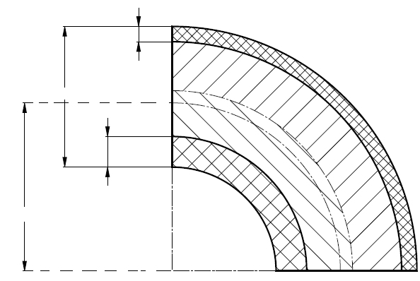
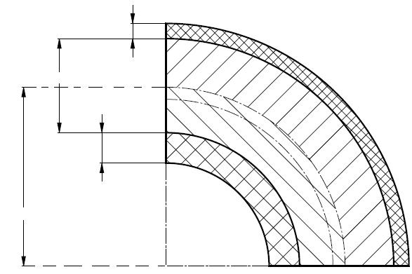
Standard and calculation basis: AD 2000 B1 Anlage 1: 2006-05
Calculation workflow
- Define the bend geometry: The inputs are the pipe diameter, the radius of curvature and the reference of the radius (referred to the inside or outside diameter), together with the calculation option — a free bend with individual wall thicknesses or a standard bend to DIN 2605 / DIN 2606.
- Determine the wall thickness of the connected straight pipe: The starting point is the calculated wall thickness of the straight pipe under internal pressure to AD 2000 B1, from the pressure, the diameter, the strength value K, the safety factor S and the joint efficiency v.
- Apply the bend factors for intrados and extrados: From the ratio of the radius of curvature to the pipe diameter, the coefficients follow with which the required wall thickness is increased at the inside of the bend and reduced at the outside. The tighter the bend, the larger the increase at the intrados.
- Add the allowances and compare with the actual wall thicknesses: After adding the allowances for tolerance and corrosion, the required wall thicknesses are compared with the existing wall thicknesses or those to be expected after bending — at the outer bend, the thinning caused by fabrication must be applied.
- Verify standard bends via the integrated tables: For bends of uniform wall thickness to DIN 2605 (3-d) and DIN 2606 (5-d), the module draws on the stored table values and directly verifies the suitability of the selected fitting.
Input quantities
| Quantity | Symbol | Unit |
|---|---|---|
| Design pressure | P | bar |
| Design pressure | P | MPa |
| Design temperature | t | °C |
| Inside diameter | di | mm |
| Outside diameter | da | mm |
| Radius of curvature | r | mm |
| Radius of curvature | r | mm |
| Final wall thickness | se | mm |
| Final wall thickness (inside) | sei | mm |
| Final wall thickness (outside) | sea | mm |
| Class (1; 2; 3; 4; 5) | BR | - |
| Material | WNr | - |
| Nominal design strength | K | N/mm² |
| Safety factor | S | - |
| Wall thickness allowance | c1 | mm |
| Corrosion / wear allowance | c2 | mm |
| Weld factor | v | - |
| Nominal width | DN | - |
| Performance ratio pall(bend)/pall(pipe) | A | % |
| Type (2; 3; 5; 10; 20) | Ba | - |
| Calculation options | Bauform | – |
Calculated results
| Quantity | Symbol | Unit |
|---|---|---|
| Allowable stress (K/S) | σall | N/mm² |
| Required cylinder thickness acc. AD B1 Eq.(2) | sv | mm |
| Ratio | r/sv (8) | mm |
| Auxiliary value | (da/2sv)²+(R/sv)² H1 | - |
| Auxiliary value | (da/2sv)·[(da/2sv)-1] H2 | - |
| Auxiliary value | (r/sv)²-(da/2sv)² H3 | - |
| Factor (inside) | Bi (7) | - |
| Required wall thickness with allow. (inside) | si (5+1) | mm |
| Final wall thickness without allow. (inside) | svi (3) | mm |
| Mean stress (inside) | σi (19) | N/mm² |
| Factor (outside) | Ba (13) | - |
| Required wall thickness with allow. (outside) | sa (11+2) | mm |
| Final wall thickness without allow. (outside) | sva (4) | mm |
| Mean stress (outside) | σa (21) | N/mm² |
| Factor | B (15) | - |
| Required wall thickness with allowances | s (14+2) | mm |
| Proof satisfied | ) | - |
Calculation options
Calculation options
Pipe bends with given inside diameter · Pipe bends with given outside diameter · Bends according DIN 2605 Part 1 (reduced performance ratio) · Bends according DIN 2605 Part 2 (total performance ratio)
Frequently asked questions
Why does the bend need a greater wall thickness on the inside than the straight pipe?
In the curved pipe, the circumferential forces on the inside of the bend must be carried by a shorter arc length — the circumferential stress there rises above that of the straight pipe, while it drops on the outside. The effect grows as the ratio of radius of curvature to diameter decreases: a tight 1.5-d bend needs significantly more wall thickness at the intrados than a wide 5-d bend.
What do "3-d bend" and "5-d bend" mean?
They denote the radius of curvature as a multiple of the pipe diameter. Bends to DIN 2605 have a radius of curvature of about 1.5 times the diameter (classic welding elbows, frequently called "3-d" when referred to the bending diameter), bends to DIN 2606 five times the diameter. Wider radii reduce stress concentration and pressure drop, but need more installation space.
How do I account for the thinning during pipe bending?
During bending, the wall at the outer bend is stretched and thins out, at the inner bend it thickens by upsetting. As a guide value, the thinning is of the order of half the ratio of diameter to radius of curvature. For the verification, the minimum wall thickness actually present (or guaranteed) at the extrados after bending must be used — not the initial wall thickness of the straight pipe.
Does the internal pressure verification also cover the bending moments from the piping system?
No. AD 2000 B1 Annex 1 verifies the bend for internal pressure. Moments and forces from thermal expansion, dead weight and connected equipment require a piping or flexibility analysis (e.g. to EN 13480-3), in which the bend enters via flexibility and stress intensification factors. The two verifications complement each other.