Engineering task and calculation objective
The ZCF47 module calculates a spherically dished bolted cover — a bolted, dished head consisting of a spherical cap with a bolting flange ring — according to the alternative rules of paragraph 4.7.5.3, ASME Sec. VIII Div. 2, 2025 edition, for internal and external pressure. This construction combines a thin-walled spherical cap with a welded-on flange ring and is used as a pressure-retaining, removable closure for vessels, heat exchanger channels, and reactors.
The alternative analysis per 4.7.5.3 goes beyond the classical formula-based design: it evaluates the cap and the transition between cap and flange ring at stress level. Calculated are the membrane stress of the spherical cap, the local membrane stress at the cap/flange junction, and the bending as well as the combined membrane-plus-bending stress at the inside surface of the junction — each for the operating condition and the gasket seating condition, and compared with the allowable stress categories of the code.
The inputs are the materials of cap, flange, and bolts with their allowable stresses at design and gasket seating temperature, the bolting data (number, nominal and root diameter), the gasket parameters, and optional external supplementary loads (axial force and bending moment on the connection). This allows a spherically dished bolted cover to be fully calculated and evaluated to ASME VIII-2.
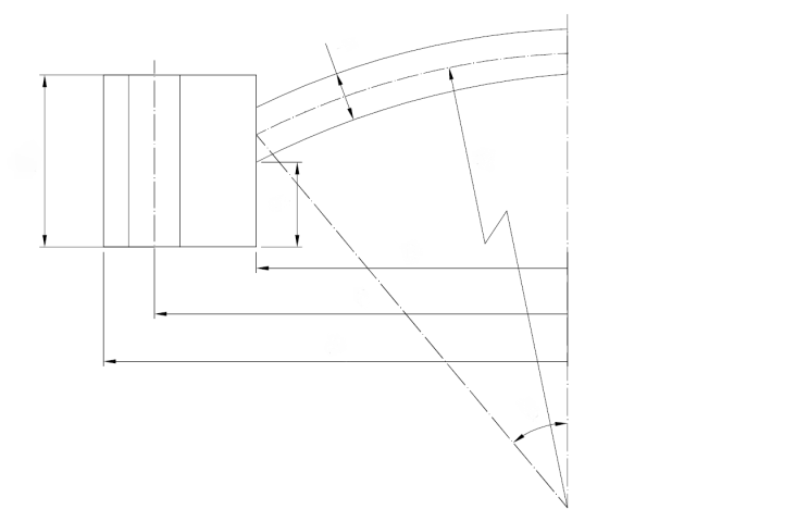
Standard and calculation basis: alternative rules 4.7.5.3, ASME Sec. VIII Div. 2 Ed2025
Calculation workflow
- Define materials and allowable stresses: For the spherical cap (head), the flange ring, and the bolts, the materials are recorded with their allowable stresses at design temperature (operating) and at gasket seating temperature, together with the associated safety factors; for the cap, additionally Poisson's ratio.
- Bolting design: From the gasket parameters and the design pressure, the required bolt loads for the operating and the gasket seating condition are determined. With the number of bolts and their nominal and root diameters, the available total bolt area is compared with the minimum required area; external supplementary loads (axial force, bending moment on the connection) increase the required bolt load.
- Stresses in the spherical cap: For internal or external pressure, the membrane stress of the spherical cap is calculated and compared with the allowable stress of the general membrane stress category.
- Stresses at the cap/flange junction: Following the alternative rules of 4.7.5.3, the local membrane stress, the bending stress, and the combined membrane-plus-bending stress at the inside surface are determined at the junction between cap and flange ring — separately for the operating and the gasket seating condition.
- Evaluation by stress categories: All calculated stresses are compared with the allowable limits of their category (general membrane, local membrane, membrane plus bending) in the respective load case. The verification is satisfied when all utilization ratios are below 100%.
Input quantities
| Quantity | Symbol | Unit |
|---|---|---|
| Variable 3 | pi | – |
| Variable 4 | pei | – |
| Variable 5 | pe | – |
| Variable 6 | pee | – |
| Variable 7 | B | – |
| Variable 8 | C | – |
| Variable 9 | A | – |
| Variable 10 | T | – |
| Variable 11 | R | – |
| Variable 12 | t | – |
| Variable 13 | q | – |
| Variable 14 | – | – |
| Variable 15 | m | – |
| Variable 16 | y | – |
| Variable 17 | N | – |
| Variable 18 | T | – |
| Variable 19 | w | – |
| Variable 20 | b | – |
| Variable 21 | G | – |
| Variable 22 | W0 | – |
| Variable 23 | n | – |
| Variable 24 | a | – |
| Variable 25 | d | – |
| Variable 26 | – | – |
Calculation options
Variable 14
non_self_energized · self_energized
Variable 103
internal · external
Frequently asked questions
What distinguishes the alternative rules of 4.7.5.3 from the classical design of dished bolted covers?
The classical design-by-rule approach (in ASME VIII-1 Appendix 1-6 and the basic rules of VIII-2 4.7) works with closed design formulas for the cap thickness and the flange ring. The alternative method per 4.7.5.3 instead performs a categorized stress verification at the cap/flange junction: local membrane and bending stresses are calculated explicitly and checked against the limits of the respective stress category. This yields a more realistic evaluation and often more economical dimensions, particularly for configurations where the classical formulas are unnecessarily conservative or not applicable at all.
Why must the operating condition and the gasket seating condition be verified separately?
In the gasket seating condition, the full bolt preload acts to seat the gasket without any relieving internal pressure — often at room temperature with different allowable stresses. In the operating condition, the reduced bolt load, the pressure force on the cover, and the gasket reaction at design temperature superimpose. Both conditions produce different moment distributions in the flange ring and at the cap junction; which one governs depends on gasket type and temperature and cannot be decided in advance.
How do external supplementary loads enter the calculation?
An external axial tensile force and a bending moment on the connection (net-section axial force and bending moment) increase the load to be carried by the bolts and shift the load distribution around the circumference. ASME VIII-2 converts the bending moment into an additional bolt loading via an equivalent pressure or force approach. If such loads — for example from connected piping — are ignored, the joint can leak in service even though the pure pressure verification is satisfied.
Does the verification also cover external pressure?
Yes, the module covers internal and external pressure. Under external pressure, the signs of the membrane stresses in the cap reverse; in addition to the stress verification per 4.7.5.3, the buckling resistance of the pressure-loaded convex cap must in principle also be considered per the external pressure rules (VIII-2, 4.4).