Engineering task and calculation objective
Module ABDR calculates the stresses in tees and branch connections under external loads to ANSI/ASME B31.3 (1980 Edition), the American code for process piping. Branch outlets and fittings frequently have smaller wall thicknesses than the run pipe and branch pipe, and the geometric discontinuity additionally acts as a stress raiser. A separate strength check is therefore required for these regions whenever piping moments from dead weight, thermal expansion or connected equipment act in addition to the internal pressure.
From the entered in-plane and out-of-plane bending moments and the torsional moment, the program determines — separately for the run pipe and the branch — the bending stress, the torsional stress and the resulting combined stress. Stress intensification factors to B31.3 account for the notch effect of the tee, whether it is a welded, preformed or extruded fitting. Comparing the result with the allowable stress of the material at design temperature completes the check.
Typical applications are nozzle load checks in piping engineering and the assessment of branches for which a full piping system analysis is not available or whose results are to be spot-checked.
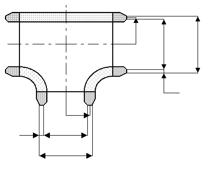
Standard and calculation basis: ANSI/ASME B31.3-1980 Edition
Calculation workflow
- Define geometry and material: The dimensions of the run and the branch (diameters, wall thicknesses), the material, and the design pressure and design temperature are entered. From these, the allowable stress to B31.3 for the operating condition follows.
- Specify the section loads: For the run pipe and the branch, the in-plane bending moment, the out-of-plane bending moment and the torsional moment are specified — typically results of a piping system analysis or estimated nozzle loads.
- Determine the stress intensification factors: Depending on the type of tee (welded tee, welding fitting, extruded outlet), the stress intensification factors ii and io are applied according to Appendix D of B31.3. They capture the increased fatigue loading at the intersection compared with the plain pipe.
- Calculate bending and torsional stress: The bending stress follows from the moments weighted with ii and io, referred to the section modulus of the respective cross-section; the torsional stress follows from the torsional moment and twice the section modulus. For the branch, an effective section modulus with the governing wall thickness is used.
- Form the resulting stress and evaluate: Bending and torsional stress are combined into the resulting stress and compared, separately for the run and the branch, with the allowable stress. Exceedances require larger wall thicknesses, reinforcement or a reduction of the piping loads.
Input quantities
| Quantity | Symbol | Unit |
|---|---|---|
| Torsion stress | σt | N/mm² |
| Resulting stress | σe | N/mm² |
| Bending stress | σb | N/mm² |
| Bending stress | σba | N/mm² |
| i_i | ii = io = | - |
| i_o | ii = io = | - |
| Torsion moment | Mt | N·mm |
| Tube Inner moment | Mi | N·mm |
| Outer moment | Mo | N·mm |
| Inside pipe diameter | di | mm |
| Outside pipe diameter | do | mm |
| Outside branch diameter | Db | mm |
| Mean tube radius | r2 | mm |
| Tube thickness | T | mm |
| Branch thickness | Tb | mm |
| Basic body | ≤ | N/mm² |
| Branch | ≤ | N/mm² |
| Torsion stress | σta | N/mm² |
| Resulting stress | σea | N/mm² |
| Branch Inner moment | Mia | N·mm |
| Outer moment | Moa | N·mm |
| Torsion moment | Mta | N·mm |
| Inside branch diameter | db | mm |
| Design temperature | T0 | °C |
Worked example
At the run pipe of a welded DN 200 tee (pipe 219.1 × 8.18 mm), an in-plane moment, an out-of-plane moment and a torsional moment act, taken from the piping system analysis. This worked example determines the bending stress, torsional stress and resulting stress in the run pipe to ASME B31.3.
Given values
| Pipe outside diameter D | 219.1 mm |
| Wall thickness t | 8.18 mm |
| In-plane moment Mi | 8.0 kNm |
| Out-of-plane moment Mo | 5.0 kNm |
| Torsional moment Mt | 4.0 kNm |
| Stress intensification factors ii / io | 2.3 / 1.9 (construction type, App. D) |
Solution
Section modulus of the pipe cross-section
Inside diameter d = 219.1 − 2 · 8.18 = 202.74 mm
Z = (π/32) · (D⁴ − d⁴)/D = (π/32) · (219.1⁴ − 202.74⁴)/219.1 ≈ 275,554 mm³ ≈ 275.6 cm³
Bending stress with stress intensification
Sb = √[(ii·Mi)² + (io·Mo)²] / Z
ii·Mi = 2.3 · 8.0 = 18.4 kNm; io·Mo = 1.9 · 5.0 = 9.5 kNm
Sb = √(18.4² + 9.5²) · 10⁶ / 275,554 = 20.71 · 10⁶ / 275,554 ≈ 75.2 N/mm²
Torsional stress
St = Mt / (2·Z) = 4.0 · 10⁶ / (2 · 275,554) ≈ 7.3 N/mm²
Resulting stress
SE = √(Sb² + 4·St²) = √(75.2² + 4 · 7.3²) ≈ 76.5 N/mm²
This value is compared with the allowable stress (range) to B31.3; for common carbon steels it is well within the allowable range.
Result
| Section modulus Z | ≈ 275.6 cm³ |
| Bending stress Sb | ≈ 75.2 N/mm² |
| Torsional stress St | ≈ 7.3 N/mm² |
| Resulting stress SE | ≈ 76.5 N/mm² |
All values are illustrative. The applicable standard and project-specific boundary conditions remain authoritative.
Frequently asked questions
What do the stress intensification factors ii and io mean?
The stress intensification factors of ASME B31.3 Appendix D indicate by which factor the fatigue effect of a bending moment at a fitting is greater than at a straight pipe of the same dimensions. ii applies to moments in the plane of the component (in-plane), io to moments perpendicular to it (out-of-plane). They depend on the construction type (welded tee, extruded outlet, unreinforced fabricated branch) and on the radius-to-wall-thickness ratio. They are largest for unreinforced welded-on branch connections.
Does this check replace the wall thickness calculation for internal pressure?
No. The module evaluates the additional stresses from external moments (nozzle loads, thermal expansion, weight). The required wall thickness for internal pressure and the opening reinforcement of the branch must be verified separately according to the pressure design rules of B31.3 (or the applicable code). Only both checks together give the complete assessment of the tee.
Where do I get the moments for the run pipe and the branch?
Usually from a piping system calculation (flexibility analysis) that superimposes weight, pressure and thermal expansion load cases. If no analysis results are available, allowable nozzle loads from the equipment manufacturer or values based on experience are applied conservatively. Consistent assignment is important: in-plane and out-of-plane moments refer to the plane of the tee, not to a global coordinate system.
Does the calculation also apply to current editions of B31.3?
The module is based on the 1980 Edition. The basic methodology — intensified bending stresses plus torsion, comparison with the allowable stress range — has been retained in later editions; individual i-factors and the treatment of the branch section modulus, however, have been revised (today, among others, in ASME B31J). For checks to the current code, the factors of the applicable edition should be cross-checked.