Engineering task and calculation objective
Module 12516A calculates circular flanges on valve bodies to DIN EN 12516-2, the European standard governing the shell strength of industrial steel valves. It covers weld-neck flanges, hubbed slip-on welding flanges and loose (lap-joint) flanges as connecting elements of valve bodies under internal pressure. Engineers who want to calculate a valve flange to DIN EN 12516-2 use this module to verify that the flange cross-sections can carry the moments from bolt and gasket forces in every load condition.
In practice this verification is needed when designing valve, gate valve and butterfly valve bodies: for new designs, for re-rating existing bodies to changed pressure/temperature classes, and for determining the maximum allowable pressure of an existing flange. The method follows the classic moment-resistance concept: bending moments are formed from the lever arms of the acting forces and compared with the flange resistances in the governing cross-sections.
To this end the module determines the geometric auxiliary quantities such as the reduced bolt-hole diameter, twice the flange width and the mean hub wall thickness, as well as the lever arms for the operating, test and bolting-up conditions.
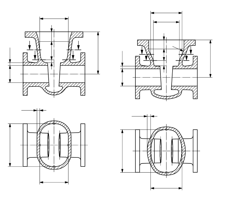
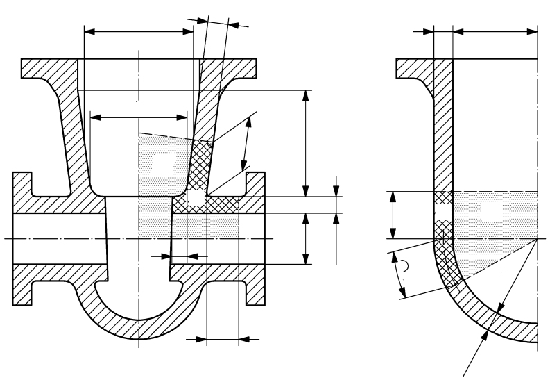
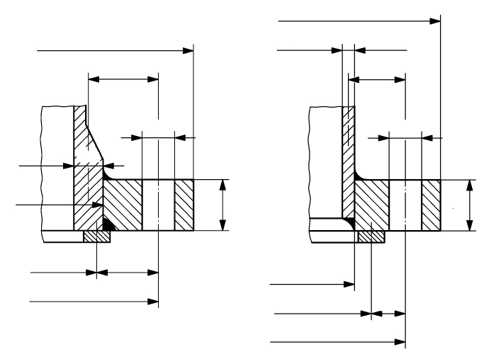
Standard and calculation basis: DIN EN 12516-2: 2022-08
Calculation scope
- Circular flanges
- Valve bodies
Calculation workflow
- Select base body and calculation objective: First it is decided whether the flange geometry is to be re-checked or the maximum allowable pressure is to be determined, and the corresponding base body (weld-neck flange, hubbed slip-on welding flange or loose flange) is selected.
- Enter the geometry: The flange dimensions are entered; from these the module determines derived quantities such as the reduced bolt-hole diameter, twice the flange width and the mean wall thickness of the hub.
- Determine lever arms: For cross-sections I-I and II-II the lever arms of the bolt and gasket forces are calculated for the operating and test conditions, together with the lever arm for the bolting-up condition.
- Compare moments and flange resistances: Forces and lever arms yield the bending moments in the governing cross-sections. These are compared with the available flange resistances; the strength condition is satisfied when the available resistance meets the required one in every load condition.
Input quantities
| Quantity | Symbol | Unit |
|---|---|---|
| Required wall thickness | e0 | mm |
| Outside diameter | da | mm |
| Nominal design strength (operation) | K | N/mm² |
| Safety factor (operation) | S | – |
| Joint efficiency factor | kC | – |
| Wall thickness allowance | c1 | mm |
| Corrosion allowance | c2 | mm |
| Final wall thickness | en | mm |
| Angle | φ | ° |
| Test pressure | p' | MPa(p) |
| Angle welding | Eckschweißung | – |
| Ratio | (e-c1-c2)/do | – |
| Design pressure | p | MPa(p) |
| Safety factor (test) | S' | – |
| Nominal design strength (test) | K' | N/mm² |
| Required wall thickness (operation) | e0B | mm |
| Required wall thickness (test) | e0P | mm |
| Radius of curvature | r | mm |
| Run-out length outside the knuckle | x | mm |
| Material | WNr | – |
| Allowable stress | f f' | N/mm² |
| Design temperature | T | °C |
| Ratio | do/di | - |
| Allowable stress | f f' | N/mm² |
Calculation options
Angle welding
No · Yes
Load case
Operation · Testing
For installation: Always use the allowable stress for test?
No · Yes
J/
Yes · No
Metal-to-metal contact type gasket?
No · Yes
Calculation of
Casing under predominantly stationary loading · Round flanges
Casing option
Cylindrical basic bodies without openings · Spherical basic bodies without openings · Basic bodies with oval cross sections without openings · Conical basic bodies without openings · Basic bodies with square cross sections without openings · Basic bodies with branch according 7.2.3
Flange option
Welding-neck flange with conical hub · Slip-on and integral type flanges · Reverse slip-on weld flange · Loose-type flanges
Frequently asked questions
How does the flange calculation to DIN EN 12516-2 differ from that to DIN EN 1591-1?
DIN EN 12516-2 uses a comparatively simple moment-resistance method tailored to valve bodies, which requires no iteration and does not verify tightness classes. DIN EN 1591-1 is an iterative force-deformation method for bolted flange connections with a leak-tightness verification. For body flanges of industrial valves, the DIN EN 12516-2 method is the purpose-built code.
Which flange types does the module cover?
Weld-neck flanges, hubbed slip-on welding flanges and loose (lap-joint) flanges on circular bodies under internal pressure. Oval and rectangular flanges as well as self-sealing closures are handled in the sister module 12516B to the same clauses of the standard.
Why are several cross-sections (I-I and II-II) verified?
For a weld-neck flange, either the transition to the hub (cross-section I-I) or the cross-section weakened by the bolt holes (II-II) can become governing. The standard therefore requires the moment comparison in both cross-sections, each for the operating, test and bolting-up conditions; the least favourable ratio determines the utilization.
What does the reduced bolt-hole diameter mean?
The bolt holes do not weaken the flange ring by their full size, because the material between the holes also carries load. The standard therefore applies a computationally reduced hole diameter, which depends on the hole diameter and the bolt pitch and enters the flange resistance of cross-section II-II.