Engineering task and calculation objective
This module provides the dimensions of circular steel flanges to DIN EN 1092-1 — from PN 2.5 to PN 400 and for all standardized flange types: welding-neck flanges (type 11), plate flanges for welding, loose flanges with hub or lapped pipe end, threaded flanges, and blind flanges (type 05). For every combination of nominal size, pressure rating, and flange type, the program delivers the complete table dimensions: pipe connection size and pipe wall thickness, hub thickness and hub length, sealing face dimensions including tongue and groove sizes, bolt circle, bolt hole diameter, number of holes, and thread.
Beyond the pure dimensions, the module also implements the pressure-temperature rating of the standard: Annex G assigns model materials with tabulated allowable pressures at elevated temperature to the material groups, and Annex F allows the allowable operating pressure to be calculated for your own flange materials. Matching bolt materials and strength classes are covered in EN 1515-1 and EN 1515-2.
In practice, the module is the standard tool for selecting and sizing flanges to EN 1092-1 — whether for the nozzle schedule of a pressure vessel, piping design, or comparison with existing flanges to the old DIN standards. The dimensions flow directly into downstream calculations, for example the flange verification to DIN EN 1591-1.
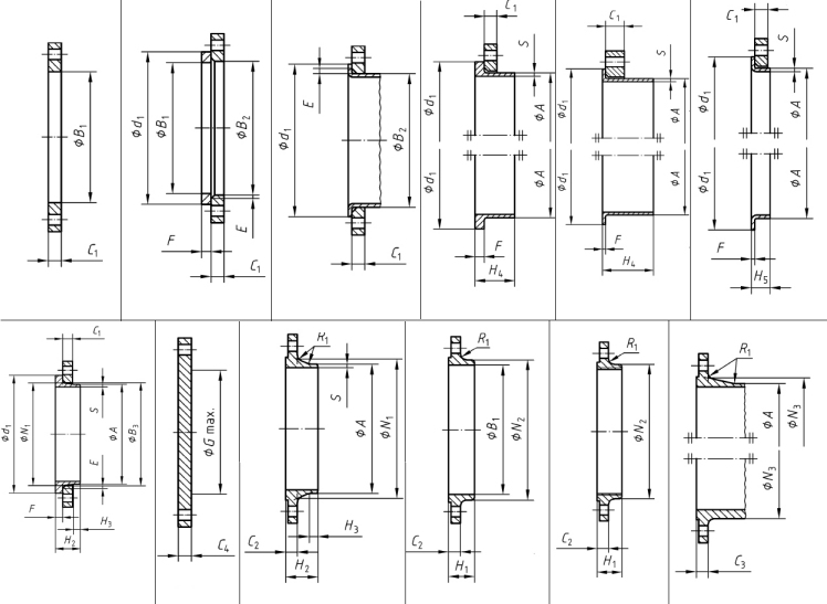
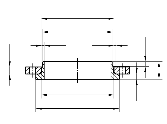
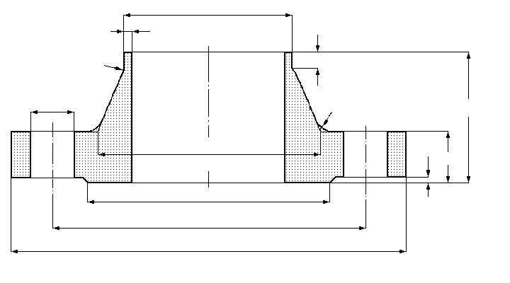
Standard and calculation basis: DIN EN 1092-1: 2018-12
Calculation workflow
- Select flange type, nominal size, and pressure rating: First, the flange type (e.g. type 11 welding-neck flange or type 05 blind flange), nominal size DN, and nominal pressure rating from PN 2.5 to PN 400 are selected. This determines the governing dimension table of the standard.
- Define the sealing face: The sealing face type (e.g. form B1/B2 raised face, tongue and groove, male and female, or ring joint) is selected; the module delivers the associated diameters, depths, and radii.
- Output the dimensions: The module reads out all table dimensions: pipe connection size and pipe wall thickness, inside diameter, hub thickness at the transition N1 and hub length, bolt circle, number and diameter of bolt holes, and the bolt thread.
- Check the allowable operating pressure: Using the pressure-temperature rating per Annex G, it is checked whether the combination of material group, operating temperature, and operating pressure lies within the table values; for materials not listed, the allowable pressure can be calculated using the equations of Annex F.
- Assign bolts and gasket: Finally, the bolt material and strength class per EN 1515-1/-2 and a gasket matching the sealing face (e.g. to DIN EN 1514-1) are selected.
Input quantities
| Quantity | Symbol | Unit |
|---|---|---|
| Nominal pressure | PN | - |
| Nominal diameter | DN | – |
| Pipe diameter Pipe thickness | A Sp | mm |
| Outside diameter Thickness | D C2 | mm |
| Outside diameter Thickness | D C2 | mm |
| Bolt circle diameter Total length | K H2 | mm |
| Bolt circle diameter Total length | K H2 | mm |
| Diameter Hub thickness | N1 S | mm |
| Diameter Hub thickness | N1 S | mm |
| Radius Hub length | R1 H3 | mm |
| Radius Hub length | R1 H3 | mm |
| Diameter Depth | d1 f1 | mm |
| Diameter Depth | d1 f1 | mm |
| Bolt hole diameter Number | L n | - |
| Bolt hole diameter Number | L n | mm |
| Thread | M | - |
| Inside diameter | di | mm |
| Pipe diameter Pipe thickness | A Sp | mm |
| Allowable pressure (for model flange acc. tables in Appendix G) for reference temperature for flange selection | PS | bar |
| Operating temperature | (20°C - 600°C) | °C |
| Material group | (1-6) | – |
| Material | 1092-1 | – |
| f2 | f2 f3 f4 | mm |
| f3 | f2 f3 f4 | mm |
Calculation options
Flange (combination)
Type 01: Weld on plate flange · Loose flange type 02 with weld on plate collar type 32 · Loose flange type 02 with lapped pipe end type 33 · Loose flange type 02 with weld-neck ring type 35 · Loose flange type 02 with long pressed lapped end type 36 · Loose flange type 02 with weld-neck ring type 37 · Loose flange type 04 with weld-neck collar type 34 · Type 05: Blank (Blind) flange · Type 11: Weld-neck flange · Type 12: Weld on flange with hub · Type 13: Thread flange with hub · Type 21: Integral flange
Frequently asked questions
Does the pressure-temperature rating per Annex G replace a flange calculation?
For standard applications without significant additional loads, yes — the rating covers internal pressure and temperature. However, it accounts for neither external forces and moments from the piping system nor special tightness requirements. In such cases, a calculated verification of the complete joint is required, for example to DIN EN 1591-1 or DIN EN 13445-3 Annex G.
Are flanges to EN 1092-1 interchangeable with old DIN flanges?
The connection dimensions (bolt circle, bolt pattern, outside diameter) were largely carried over from the old DIN standards, so the flanges can be bolted together in most DN/PN combinations. Differences exist in some flange thicknesses, sealing faces, and individual nominal sizes; a dimension check is advisable for mixed joints.
What does the material group mean in the pressure-temperature rating?
Annex G groups flange materials with similar strength behavior and assigns each group a model material whose characteristic values determine the table values. Your own material must be assigned to a group; if it is more favorable than the model material, the table values are conservative, otherwise the calculation must be done per Annex F.
Which flange type is suitable for high pressures and temperatures?
For high loading, the welding-neck flange (type 11) is the first choice: the tapered hub transfers the forces favorably into the pipe and can be fully welded through. Loose flanges and threaded flanges are limited to lower pressure ratings; blind flanges follow their own thickness tables.