Engineering task and calculation objective
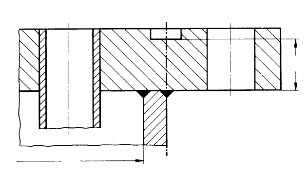
Many shell-and-tube heat exchangers are built with tubesheets whose rim extends beyond the shell as a flange: the tubesheet is at the same time the sealing surface and is bolted between the shell flange and the channel flange. The protruding flange rim is subjected to bending moments from bolt load, gasket load and pressure — a loading condition that neither the pure plate calculation nor the pure flange calculation covers on its own.
The B51C module calculates circular flat tubesheets with protruding flange rims on the basis of AD 2000-Merkblatt B5 — part of the German AD 2000 pressure vessel code — in conjunction with DIN 2505. From the bolt load at bolting-up, the gasket load in operation, the ring area force and any additional tube bundle forces, the bending moments in the flange rim are formed via the respective lever arms and compared with the flange section modulus. In particular, the critical cross-section C-C at the transition from the flange rim to the tubed plate field is verified — separately for the bolting-up and the operating condition.
The module complements the tubesheet design to B51: while B51 determines the plate thickness within the tube field, B51C verifies the flange rim and the bolted joint of the tubesheet. Typical applications are fixed-tubesheet and floating-head exchangers in which the tubesheet is clamped between the flanges.
Standard and calculation basis: AD 2000 B5: 2016-09 & DIN 2505
Calculation workflow
- Enter geometry and loads: The inputs are the nominal flange width, the equivalent diameter of the plate, the design pressure and design temperature, and the forces: bolt load at bolting-up, gasket load in operation, ring area force from the pressure and, if applicable, an additional tube force from the bundle.
- Determine material properties for bolting-up and operation: For the flange material, the design strength value and the safety factor are applied separately for the bolting-up condition (room temperature) and the operating condition (design temperature); the stress deformation factor per Equation 18 is added.
- Form lever arms and bending moments: The lever arms follow from the positions of the bolt circle, the gasket and the ring area. With these, the bending moments are calculated for the bolting-up condition (bolt load times lever arm) and the operating condition (superposition of pressure, gasket and tube forces); in each case the maximum bending moment governs.
- Verify cross-section C-C: The flange section modulus of the protruding rim is compared with the bending moments at cross-section C-C. The verification is carried out separately for the bolting-up and the operating condition with the respective allowable stresses.
- Evaluate the strength conditions: The module reports in summary whether the strength conditions are satisfied in all conditions. If a verification fails, the flange rim thickness, gasket position or bolt loads must be adjusted and the calculation repeated.
Input quantities
| Quantity | Symbol | Unit |
|---|---|---|
| Flange section modulus | W0CC 14e | mm³ |
| Final flange thickness | hf | – |
| Flange outside diameter | da | mm |
| Bolt hole diameter | dL | mm |
| Nominal width flange | DN | mm |
| Equivalent diameter | d'L | mm |
| Bolt load Bolting-up | PS0 | N |
| Gasket load reaction Operating | pDB | N |
| Moment arm | (dt-dD)/2 aD | mm |
| Moment arm | (2dt-d-dD)/4 aF | mm |
| Moment arm | (dt-d-sR)/2 aR | mm |
| Mean gasket diameter | dD | mm |
| Pitch circle diameter | dt | mm |
| Inside diameter | d | mm |
| Wall thickness | sR | mm |
| Bolting-up Cross section C-C | M/W ≤ = K/(S*z) 18 | N/mm² |
| Operating Cross section C-C | M/W ≤ = K/(S*z) 18 | N/mm² |
| Design strength value Bolting-up | K0 | N/mm² |
| Design strength value Operating | K1 | N/mm² |
| Safety factor Bolting-up | S0 | - |
| Safety factor Operating | S1 | - |
| Operating Bending moment | (aD) M1CC 13b | N·mm |
| Bolting-up Bending moment | (aD) M0CC 13b | N·mm |
| Stress deformation factor (Equation 18) | z | - |
Frequently asked questions
Why is the tubesheet verified here in addition to B51?
B51 sizes the plate thickness within the tubed field against the differential pressure. The protruding flange rim, however, is loaded in bending by the bolt and gasket forces just like a flange ring. This peripheral moment can govern the design where bolt loads are high or lever arms are large, and requires the separate verification to B5 in conjunction with DIN 2505.
What is cross-section C-C?
Cross-section C-C lies at the transition from the free flange rim to the clamped or tubed plate region — where the bending moment from the rim forces meets the weakened plate cross-section. It is usually the critical location of the design and is therefore evaluated separately for the bolting-up and the operating condition.
What role does the additional tube force play?
In fixed-tubesheet exchangers, the tube bundle bears axially on the tubesheet; the pressure differential and restrained thermal expansion produce a resultant tube force that acts on the flange rim as an additional shear force or moment. It is summed into the total tube force and must not be neglected for firmly anchored tubesheets.
Why can the bolting-up condition govern even though no pressure is acting?
At bolting-up, the full bolt preload acts through the lever arm to the gasket without any relieving pressure component. At the same time, the design strength value at room temperature applies, which does not always compensate for the ratio. Especially with soft gaskets requiring a high initial seating load, the bolting-up condition frequently produces the larger bending moment.