Engineering task and calculation objective
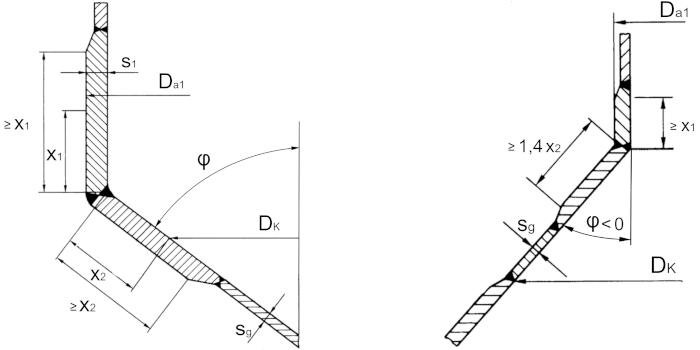
Conical shells connect cylinders of different diameters in apparatus, form the outlets of silos and hoppers, or serve as transitions to nozzles and domes. From a strength point of view, a cone consists of two regions: the undisturbed conical shell, which behaves similarly to a cylinder with an enlarged effective diameter, and the transition region to the cylinder, where additional bending stresses arise from the change in direction of the wall. Anyone who wants to calculate a conical shell to the German AD 2000 code must verify both regions — the governing code sheet is AD 2000-Merkblatt B2.
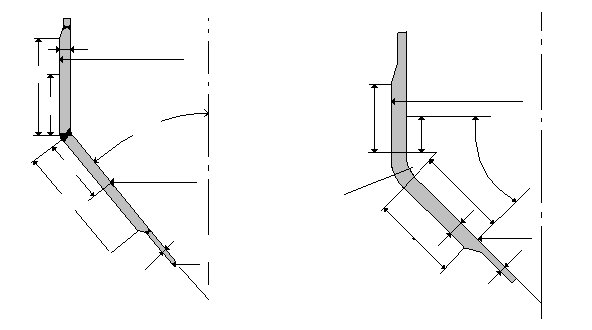
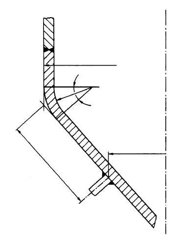
Module B2 determines the decay length within which the discontinuity stresses of the transition act, the required wall thickness in the transition region between cylinder and cone, and the required wall thickness of the conical shell outside the decay region — for internal and external pressure. Convergent and divergent cones are distinguished; for divergent cones (φ < 0) a reinforcement ring to section 8.2.4 can be provided, and for steep cones with φ > 70° special rules apply.
Typical applications are reducers in columns and vessels, conical bottom outlets of agitated vessels and silos, and transition pieces in piping engineering.
Standard and calculation basis: AD 2000 B2: 2000-10
Calculation workflow
- Define the cone geometry and load case: The inputs are the large and small diameter, the semi-apex angle φ and the wall thicknesses; the options select whether the calculation is for internal or external pressure and whether the cone is convergent or divergent. For φ > 70°, the module points out the different treatment of very steep cones.
- Calculate the wall thickness of the conical shell outside the discontinuity zone: The undisturbed conical shell is treated like a cylindrical shell with the effective diameter enlarged by 1/cos φ: the steeper the cone, the greater the required wall thickness for the same large diameter.
- Verify the cylinder-to-cone transition region: Additional bending stresses arise at the transition. The required wall thickness there is determined with a coefficient that depends on the apex angle and the geometry; it is generally greater than in the undisturbed shell.
- Determine the decay length: The module calculates the decay length over which the reinforced wall thickness must be maintained at least on both sides of the transition. Only outside this zone may the thickness be stepped down to the shell thickness.
- Assess the reinforcement ring for divergent cones: For divergent cones (φ < 0), the deviation force at the transition can be taken by a reinforcement ring to section 8.2.4; the module sizes the ring or takes it into account in the verification. For external pressure, the stability of the cone must additionally be checked.
Input quantities
| Quantity | Symbol | Unit |
|---|---|---|
| Outside diameter | Da1 | mm |
| Calculation diameter (For φ<0 specify largest cone diameter) | Dk | mm |
| Design pressure | p | bar |
| Nominal design strength (operating) | K | N/mm² |
| Safety factor (operating) | S | - |
| Joint efficiency (taper area) | v | - |
| Wall thickness manufacturing tolerance | c1 | mm |
| Corrosion / erosion allowance | c2 | mm |
| Semi-apex angle (φ<0 for divergent cones) | φ | ° |
| Run-out length cylinder | x1 | mm |
| Run-out length cone | x2 | mm |
| Run-out length cylinder with knuckle | x3 | mm |
| Final knuckle radius (interpolation range r<0.15·Da1 for φ>0) | r | mm |
| Final wall thickness (taper area) | sle | mm |
| Final wall thickness | sge | mm |
| Cone length with knuckle | l | mm |
| Material weight | G | kN |
| Weight filled with operation medium | Gb | kN |
| Weight filled with water | Gw | kN |
| Volume | Vt | m³ |
| Small outside diameter | Da2 | mm |
| Safety factor (Test) | S' | - |
| Nominal design strength (Test) | K' | N/mm² |
| Material | Nr | - |
Calculated results
| Quantity | Symbol | Unit |
|---|---|---|
| Run-out length cylinder | x1 | mm |
| Run-out length cone | x2 | mm |
| Run-out length cylinder with knuckle | x3 | mm |
| Material weight | G | kN |
| Weight filled with operation medium | Gb | kN |
| Weight filled with water | Gw | kN |
| Volume | Vt | m³ |
| Remarks | Bemerkung | - |
| 2 | 2 | - |
| Operating Test | sl sl | mm |
| Operating Test | sl sl | mm |
| Operating Test | sg sg | mm |
| Operating Test | sg sg | mm |
| Equivalent cylinder diameter | Da = (Da1 + Da2) / 2cos(φ) | mm |
| Equivalent cylinder length | l | mm |
| Run-out length cone 2 under test conditions | x2' | mm |
Calculation options
φ > 70° ?
No · Yes
Calculation for
Internal pressure · External pressure
Do you want to provide a reinforcement ring according to § 8.2.4 for divergent cones (φ < 0)?
No · Yes
Worked example
A convergent transition piece made of P265GH connects two vessel courses — a worked example of conical shell calculation to AD 2000 B2. Large cone outside diameter 1,200 mm, semi-apex angle φ = 30°, design pressure 6 bar, design temperature 20 °C, weld joint efficiency v = 0.85. Find the required wall thickness of the conical shell outside the decay region.
Given values
| Large outside diameter Da | 1,200 mm |
| Semi-apex angle φ | 30° |
| Design pressure p | 6 bar |
| Strength value K (P265GH, 20 °C) | 265 N/mm² |
| Safety factor S | 1.5 |
| Joint efficiency v | 0.85 |
| Allowances c1 + c2 (assumed) | 0.3 mm + 1.0 mm |
Solution
Formula for the conical shell outside the discontinuity zone
The conical shell is treated like a cylindrical shell with the effective diameter enlarged by 1/cos φ:
s = Da · p / (20 · (K/S) · v + p) · 1/cos φ
Wall thickness of the equivalent cylinder
K/S = 265 / 1.5 = 176.7 N/mm²
Denominator: 20 · 176.7 · 0.85 + 6 = 3,009.3
scyl = 1,200 · 6 / 3,009.3 = 2.39 mm
Cone factor and allowances
cos 30° = 0.866
s = 2.39 / 0.866 = 2.76 mm
sreq = 2.76 + 0.3 + 1.0 = 4.06 mm → selected e.g. 5 mm.
The transition region to the cylinder must be verified separately with the angle-dependent coefficient and generally yields a greater wall thickness there.
Result
| Required wall thickness of conical shell (without allowances) | 2.76 mm |
| Required wall thickness incl. c1 + c2 | 4.06 mm |
| Selected nominal wall thickness | 5 mm |
All values are illustrative. The applicable standard and project-specific boundary conditions remain authoritative.
Frequently asked questions
Why does the conical shell need more wall thickness than the cylinder at the same diameter?
In the cone, the load-bearing wall forces run obliquely to the vessel axis. For the circumferential load-carrying action, the radius of curvature normal to the wall is governing, and this is larger by the factor 1/cos φ than for a cylinder of the same diameter. A cone with φ = 30° therefore needs about 15 % more wall thickness, a cone with φ = 60° already twice as much.
What is the decay length?
The bending disturbance at the cylinder-to-cone transition decays exponentially with the distance from the transition edge. The decay length indicates up to which distance the increased wall thickness of the transition region must be maintained; it depends on the diameter and the wall thickness. Welds and wall thickness steps should lie outside this zone.
What is the difference between a convergent and a divergent cone?
With a convergent cone, the cross-section narrows towards the junction considered; with a divergent cone (φ < 0) it widens. At a divergent transition, the deviation force at the cone junction acts inwards and produces a ring-shaped compressive loading of the transition zone — which is why a reinforcement ring to 8.2.4 may become necessary there to take this force.
Does the verification to B2 fully cover external pressure as well?
B2 provides the strength verification for internal and external pressure. For external pressure or vacuum, the elastic buckling of the cone must additionally be assessed (stability check following AD 2000 B6 with the equivalent cylinder); the wall thickness formula alone does not cover buckling failure.