Engineering task and calculation objective
The cylindrical shell is the basic component of almost every pressure vessel — from the storage tank to the heat exchanger shell to the distillation column. Engineers who want to calculate the wall thickness of a cylindrical shell under internal pressure will find the governing formulas in AD 2000-Merkblatt B1 of the German AD 2000 pressure vessel code; the same approach applies there to spherical shells as well. Module B1 carries out this verification completely: from the required wall thickness through the allowances to the assessment of openings.
The required wall thickness follows from the diameter, the design pressure, the material strength value K at design temperature, the safety factor S and the joint efficiency v of the weld. Added to this are the allowance c1 for the permissible undertolerance of the semi-finished product and the corrosion allowance c2. The user selects the configuration — cylindrical or spherical shell — via the corresponding option.
For the wall thickness actually executed, the module additionally states the limiting dimensions of unreinforced openings up to which no separate opening reinforcement verification to AD 2000 B9 is required — in practice a quick decision on whether a nozzle can still be installed without additional reinforcement.
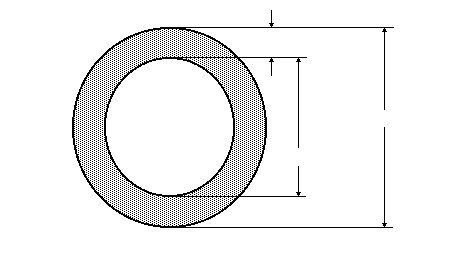
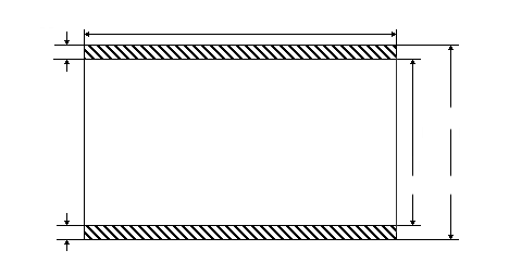
Standard and calculation basis: AD 2000 B1: 2000-10
Calculation scope
- Cylindrical shells under internal pressure
- Spherical shells under internal pressure
Calculation workflow
- Define the configuration and geometry: First the configuration is selected — cylindrical shell or spherical shell — and the governing diameter (inside or outside) is entered together with the design pressure from module B0.
- Determine material values and coefficients: From the material follows the strength value K at design temperature (usually the 0.2 % proof strength), together with the safety factor S to AD 2000 B0 and the joint efficiency v of the longitudinal weld according to the extent of weld inspection.
- Calculate the required wall thickness: The calculated wall thickness is determined from the B1 formula using diameter, pressure and allowable stress; for a spherical shell it is about half that of a cylinder of the same diameter. The allowance c₁ for the plate undertolerance and the corrosion allowance c₂ are then added.
- Select the nominal wall thickness and check the range of validity: From the sum, an available plate or pipe wall thickness is selected. The module checks the limits of validity of the code sheet (ratio of wall thickness to diameter); for thick-walled cylinders outside this range, module B10 must be used.
- State the limiting dimensions of openings: For the existing wall thickness, the module states the largest unreinforced openings for which no separate verification to AD 2000 B9 is required — the basis for a quick nozzle assessment.
Input quantities
| Quantity | Symbol | Unit |
|---|---|---|
| Outside diameter | Da | mm |
| Design pressure | p | bar |
| Nominal design strength (operation) | K | N/mm² |
| Safety factor (operation) | S | – |
| Joint efficiency factor | v | – |
| Wall thickness mill tolerance | c1 | mm |
| Corrosion / erosion allowance | c2 | mm |
| Actual wall thickness | se | mm |
| Length (Height) | L | mm |
| Weight (empty) | VB· ρ · 9.81 m/s2 GB | kN |
| Weight (water filled) | GB+VI · 1000 kg/m³ · 9.81 m/s2 GW | kN |
| Volume of the component | VA-VI VB | m³ |
| Safety factor (Test) | S' | – |
| Test pressure | p' | bar |
| Nominal design strength (Test) | K' | N/mm² |
| Allowable unreinforced opening with σall = K/S | dA1 < | mm |
| Material | WNr | – |
| Comments | 1 | – |
| Design temperature | T | °C |
| Ratio | Da/Di | – |
| 2 | 2 | – |
| Inside diameter | Da-2·se Di | mm |
| Multiple openings are isolated if l>2·b | l > | mm |
| Density | ρ | t/m³ |
Calculated results
| Quantity | Symbol | Unit |
|---|---|---|
| Required wall thickness | max(sB;sP) s | mm |
| Required wall thickness (operation) | sB | mm |
| Required wall thickness (Test) | sP | mm |
| Allowable design pressure | pallB | bar |
| Allowable test pressure | pallP | bar |
Calculation options
Type
Cylindrical shell · Spherical shell
Worked example
Determine the required wall thickness for a vessel course made of P265GH — a worked example of how to calculate wall thickness to AD 2000 B1. Outside diameter 1,000 mm, design pressure 10 bar, design temperature 20 °C. The longitudinal weld is subject to spot non-destructive testing (v = 0.85).
Given values
| Outside diameter Da | 1,000 mm |
| Design pressure p | 10 bar |
| Strength value K (P265GH, 20 °C, ReH to EN 10028-2) | 265 N/mm² |
| Safety factor S | 1.5 |
| Joint efficiency v | 0.85 |
| Allowance c1 (plate tolerance, assumed) | 0.3 mm |
| Corrosion allowance c2 | 1.0 mm |
Solution
Formula to AD 2000 B1 (referred to the outside diameter)
s = Da · p / (20 · (K/S) · v + p)
with p in bar, K in N/mm², Da and s in mm.
Calculated wall thickness
K/S = 265 / 1.5 = 176.7 N/mm²
Denominator: 20 · 176.7 · 0.85 + 10 = 3,013.3
s = 1,000 · 10 / 3,013.3 = 3.32 mm
Allowances and nominal wall thickness
sreq = s + c1 + c2 = 3.32 + 0.3 + 1.0 = 4.62 mm
The next available plate thickness is selected, e.g. 5 mm. The margin is available as additional safety or for openings.
Result
| Calculated wall thickness s | 3.32 mm |
| Required wall thickness incl. c1 + c2 | 4.62 mm |
| Selected nominal wall thickness | 5 mm |
All values are illustrative. The applicable standard and project-specific boundary conditions remain authoritative.
Frequently asked questions
Do I calculate with the inside or the outside diameter?
AD 2000 B1 provides both variants of the formula: referred to the outside diameter Da, the pressure appears in the denominator with a positive sign; referred to the inside diameter Di, with a negative sign. Both lead to the same wall thickness. In practice, one calculates with the diameter fixed by fabrication — for rolled courses frequently the inside diameter, for pipes the outside diameter.
What do the allowances c₁ and c₂ mean?
c₁ covers the permissible undertolerance of the semi-finished product (minus tolerance per the delivery standard, e.g. EN 10029 for plate); if a restricted tolerance is agreed, c₁ can be omitted. c₂ is the corrosion allowance for corrosion and erosion — for ferritic steels usually 1 mm unless greater wastage is expected; for austenitic steels and for wall thicknesses of 30 mm and above it can be omitted.
How is the joint efficiency v selected?
v rates the longitudinal weld of the shell according to the extent of non-destructive testing: v = 1.0 is permissible only with comprehensive inspection (100 % radiography or ultrasonic testing), v = 0.85 is common; without extended inspection, v = 0.7 applies. For seamless shells, v = 1.0. An over-optimistic joint efficiency is one of the most frequent sources of error in re-rating calculations.
Up to which wall thickness ratio does AD 2000 B1 apply?
The formulas of the code sheet apply to thin-walled shells; for cylinders the range of validity is limited to a diameter ratio Da/Di of about 1.2 (1.5 for spheres). Thicker-walled cylinders must be calculated to AD 2000 B10, which accounts for the non-linear stress distribution across the wall.