Engineering task and calculation objective
This module calculates flanged joints to DIN EN 1591-1 — the modern, leak-tightness-oriented verification method for flanges and their joints. It covers weld-on, welding-neck, blind, and loose flanges as a complete system of flange, bolts, gasket, and connected shell. Unlike classical methods (such as Taylor-Forge or AD 2000-Merkblatt B 8 of the German AD 2000 code), DIN EN 1591-1 treats the joint as an elastically coupled overall system: the compliances of flange ring, shell, bolts, and gasket, as well as the differential thermal expansion between the components, enter directly into the force distribution.
The method determines, for all load cases — assembly, test, operation, and start-up/shutdown conditions — the required bolt and gasket forces, the effective gasket area, and the required assembly torque. As a result, it delivers the load ratios of flange, bolts, gasket, and, where applicable, loose flange, so that load-bearing capacity and tightness are verified simultaneously.
In practice, a calculation to DIN EN 1591-1 is called for whenever a flanged joint must be designed for a defined leakage rate — for example under German TA Luft requirements, with critical media, high temperature cycling, or large additional loads from the piping system. The gasket characteristics are applied per EN 13555.
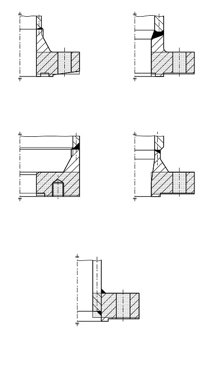
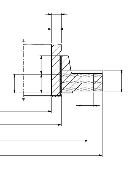
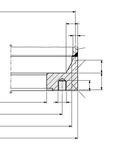
Standard and calculation basis: DIN EN 1591-1: 2014-04
Calculation workflow
- Enter geometry and materials: The flange type (welding-neck, weld-on, blind, or loose flange with stub or collar), flange and shell geometry, bolt data, and gasket dimensions are entered; for all components, strength values, moduli of elasticity, and thermal expansion coefficients are stored at the respective temperatures.
- Apply gasket characteristics per EN 13555: For the gasket, the tested characteristic values are used: required minimum surface pressures for the required leakage class, maximum allowable surface pressure, plus the unloading modulus and creep factor. From these, the effective gasket width is obtained iteratively from the force equilibrium.
- Define the load cases: For assembly, pressure test, and all operating conditions, the fluid pressure, component temperatures, and external axial forces, lateral forces, bending and torsional moments are defined (in the module via the associated 1591 load cases).
- Calculate compliances and forces: From the elastic compliances of flanges, bolts, and gasket, and the differential thermal expansions, the method calculates the force redistribution between the load cases: the required minimum bolt force at assembly is determined iteratively so that the minimum gasket force for tightness is maintained in every subsequent load case.
- Account for assembly scatter: The scatter of the tightening method (e.g. torque wrench, hydraulic tensioning) is captured via scatter factors; both the case of minimum and of maximum actual bolt force is verified, and the required assembly torque is output.
- Check the load ratios: Finally, the load limits are checked: the load ratios of flange ring, bolts, gasket (over-compression), and loose flange must remain below 100% in all load cases; otherwise the geometry, gasket, or tightening method is adjusted.
Input quantities
| Quantity | Symbol | Unit |
|---|---|---|
| Effecive area | AGe | mm² |
| Theoretical area | AGt | mm² |
| Data are incomplete or invalid according to the flange code. | berechenbar | – |
| Area for the axial fluid-pressure force | AQ | mm² |
| Modulus of elasticity | EB0 | N/mm² |
| Modulus of elasticity | EBI | N/mm² |
| Modulus of elasticity | EFI | N/mm² |
| EFI | ẼFI | N/mm² |
| Modulus of elasticity | EF0 | N/mm² |
| EF0 | ẼF0 | N/mm² |
| Modulus of elasticity | EL0 | N/mm² |
| Modulus of elasticity | ELI | N/mm² |
| ELI | ẼLI | N/mm² |
| EWI | EWI | N/mm² |
| EWI | ẼWI | N/mm² |
| Modulus of elasticity for unloading / reloading | EG0 | N/mm² |
| Average modulus of elasticity for unloading / reloading | EGm | N/mm² |
| Material | WkNr,F | – |
| Stub or collar | WkNr,F | – |
| Material (Loose flange) | WkNr,L | – |
| Loose flange | WkNr,L | – |
| Material | WkNr,B | – |
| WkNr,S | WkNr,S | – |
| WkNr,W | WkNr,W | – |
Calculated results
| Quantity | Symbol | Unit |
|---|---|---|
| Effective total cross-section area of all bolts | AB | mm² |
| Total radial cross-section area | AF | mm² |
| Total radial cross-section area | ÃF | mm² |
| Total radial cross-section area | AL | mm² |
| Total radial cross-section area | ÃL | mm² |
| Specified bolt force assembly | FB0,spec | N |
| Estimation of actual bolt force assembly | FB0av | N |
| Gasket force, replaces FG0 for load limit | FG0d | N |
| Actual gasket force | FG0 | N |
| Minimum gasket force (due to compressive stress from assembling) | FG0min | N |
| Maximum gasket force to be expected | FG0max | N |
| Nominal bolt force | FB0 nom | N |
| Nominal bolt force Maximum value of load ratio (allowable) | FB0 nom | N |
| Required gasket force | FG0req | N |
| Minimum gasket force under assembling conditions | FGΔ | N |
| Actual gasket stress | QGI | N/mm² |
| Resulting axial force | FR0 | N |
| Nominal bolt torque | Mt,nom | N·mm |
| Nominal bolt torque Maximum value of load ratio (allowable) | Mt,nom | N·mm |
| Average effective compressive stress of gasket | QG0 N/mm² | N/mm² |
| Gasket stress sufficient? | Montage | – |
| Desired gasket stress | QA | N/mm² |
| Axial modulus of elasticity Bolts | XB | 1/mm |
| Axial modulus of elasticity Gasket | XG | 1/mm |
Calculation options
Type of 1st flange
Integral hub-flange, welding-neck flange · Integral flange without hub · Blank flange · Loose flange with stub or collar
Load cases
Assembly-Test-Service · Assembly-Test-Service-Load case 1 · Assembly-Test-Service-Load case 1-Load case 2
Use leakage method?
No · Yes
Stub or collar with hub?
No · Yes
Type
cylindrical · conical · spherical
Washer / Expansion sleeve? (1st Flange)
No · Yes
Bolting method
Screw wrench · Impact wrench · Torque wrench · Measuring of hydraulic pressure · Measuring of bolt elongation · Measuring of turn of nut · Measuring of torque and turn of nut
Geometrical data of both flanges
Different · Identical
Frequently asked questions
How does DIN EN 1591-1 differ from the verification per AD 2000-Merkblatt B 7/B 8?
The German AD 2000 code performs separate strength verifications for flange and bolts using generic gasket coefficients. DIN EN 1591-1, by contrast, computes the elastic overall system: force redistributions due to compliances, thermal expansion, and gasket creep are captured explicitly, and tightness is verified via leakage classes with characteristic values per EN 13555. The method is more elaborate, but it delivers an assembly torque that ensures load-bearing capacity and tightness at the same time.
Why is the calculation iterative and not practical as a hand calculation?
The effective gasket width depends on the gasket force, which in turn depends on the flange rotation and the compliances — that produces an inner iteration. In addition, the assembly bolt force must be iterated over all subsequent load cases until the minimum gasket force is maintained in every condition. Doing this by hand is error-prone; the standard is explicitly designed for software implementation.
Which gasket characteristics do I need, and where do I get them?
You need the characteristic values per EN 13555: Q_min(L) and Q_smin(L) for the required leakage class, Q_smax as the over-compression limit, the unloading modulus E_G, and the creep factor P_QR — each as a function of temperature. Manufacturers publish these values in data sheets; a central source is the Gasketdata database. Without reliable characteristic values, a meaningful verification to 1591-1 is not possible.
Can external piping loads be taken into account?
Yes, that is a strength of the method: external axial forces and bending moments are converted into an equivalent axial force and act on the force equilibrium of the joint in every load case; lateral forces and torsional moments can also be assessed via the friction in the gasket interface. Especially for large nominal sizes, the additional loads often decide whether the joint stays tight.