Engineering task and calculation objective
The EN11 module package calculates bolted flange connections to DIN EN 13445-3, Clause 11, based on the Taylor-Forge method. It covers virtually all designs: integral flanges with and without hub, loose flanges with collar or lapped end, reverse flanges, and connections with gaskets in a force bypass (metal-to-metal contact) or full-face gaskets – each for internal and external pressure. In addition, the complete dimension tables of EN 1092-1 for pressure ratings from PN 6 upward are built in, so standard flanges can be adopted directly and verified by calculation.
Anyone performing a flange calculation to EN 13445-3 verifies two conditions: the bolting-up (assembly) condition, in which the bolt load deforms the gasket to the required seating stress, and the operating condition, in which the bolts must additionally carry the hydrostatic end force from internal pressure while maintaining the residual gasket load. From the bolt loads and their lever arms, the flange moments follow, from which the stresses in the flange ring, hub and shell are calculated and compared with the nominal design stresses – including those for the test condition.
Assembly is a further practical concern: the module documents the stress in the bolt and the maximum tightening torque per individual bolt, controlled via a bolt tightening torque factor. The calculation thus delivers not only the strength verification but also the specifications for controlled tightening of the joint.
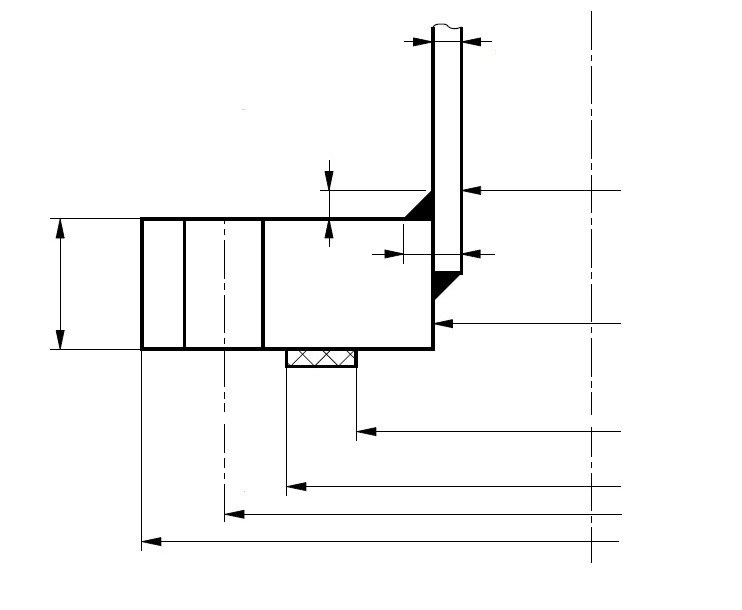
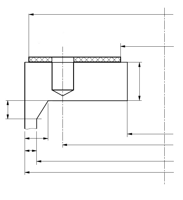
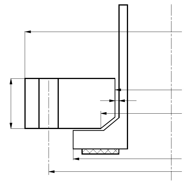
Standard and calculation basis: DIN EN 13445-3/11: 2023-12
Calculation workflow
- Define the design type and geometry: First, the flange type (integral, loose with collar, reverse flange), the gasket arrangement (inside the bolt circle, full-face, metal-to-metal contact) and the dimensions are determined – optionally taken directly from the built-in EN 1092-1 tables for the chosen PN rating and nominal size.
- Set gasket parameters and bolt data: For the gasket, the parameters for the bolting-up and operating conditions (seating and gasket factors) and the effective gasket width are determined; for the bolts, the material, root cross-section and allowable stresses at assembly, operating and test temperature.
- Calculate the required bolt loads: For the bolting-up condition, the minimum bolt load follows from the required gasket seating stress; for the operating condition, from the hydrostatic end force plus the residual gasket load. The governing load determines the required bolt cross-section or the utilization of the selected bolting.
- Determine flange moments and stresses: From the loads and their lever arms about the bolt circle, the flange moments for the bolting-up and operating conditions are formed. Following the Taylor-Forge method, the longitudinal, radial and tangential stresses in the flange ring and hub are derived and compared with the allowable values – including the nominal design stress for the test condition.
- Verify all load conditions: The bolting-up, operating and test conditions are verified separately; for external pressure or alternating conditions, the corresponding load cases are checked in addition. For lap-joint connections, loose flange and collar are checked separately, each with its own lever arms.
- Document the assembly values: Finally, the stress in the bolt and the maximum tightening torque per individual bolt are reported. Via the bolt tightening torque factor (≥ 1), the planned preload can be raised above the minimum value, for example as a reserve against gasket settlement losses.
Input quantities
| Quantity | Symbol | Unit |
|---|---|---|
| Load case | lc | – |
| Design temperature of the flange | tF | °C |
| Design pressure (internal) | P | MPa |
| Material | mcF | – |
| Corrosion allowance | c2F | mm |
| Nominal design stress (exception) | fF,Except | N/mm² |
| Nominal design stress (testing) | fFTest | N/mm² |
| Modulus of elasticity (operation) | EFOp | N/mm² |
| Modulus of elasticity (testing) | EFTest | N/mm² |
| Material | mcB | – |
| Nominal design stress (exception) | fB,Except | N/mm² |
| Nominal design stress (testing) | fBTest | N/mm² |
| Modulus of elasticity (operation) | EBOp | N/mm² |
| Modulus of elasticity (testing) | EBTest | N/mm² |
| Material | mcH | – |
| Corrosion allowance | c2H | mm |
| Nominal design stress (exception) | fH,Except | N/mm² |
| Nominal design stress (testing) | fHTest | N/mm² |
| Modulus of elasticity (operation) | EHOp | N/mm² |
| Modulus of elasticity (testing) | EHTest | N/mm² |
| Design temperature of bolts | tB | °C |
| Nominal design stress (assembly) | fFA | N/mm² |
| Nominal design stress (assembly) | fBA | N/mm² |
| Nominal design stress (assembly) | fHA | N/mm² |
Calculation options
Type of flange (Figure 11.5-1,-2, -3)
Welding-neck flange · Slip-on weld flange · Slip-on hub flange
Type of bolt
Loose flange not split · one split ring · two split rings
flagext
Internal pressure · External pressure
Method of calculation
Integral method · Loose method · Loose method with hub
Microstructure
Ferrite · Austenite · Martensite · Duplex · unknown
Data of the second flange
Identical design conditions and geometry · different design conditions or geometry
AustenitF
No Austenite · Austenite; rupture elongation < 30% · Austenite; rupture elongation ≥ 30% · Steel casting
AustenitH
No Austenite · Austenite; rupture elongation < 30% · Austenite; rupture elongation ≥ 30% · Steel casting
Frequently asked questions
How does the flange calculation to EN 13445-3 Clause 11 differ from EN 1591-1?
Clause 11 is based on the Taylor-Forge method: it checks the strength of flange and bolts using lump-sum gasket factors and is the classic, quickly applicable procedure. EN 1591-1, in contrast, treats the joint as a deformation-coupled system of flange, bolts and gasket with tightness classes, delivering consistent assembly loads for defined leakage rates. For elevated tightness requirements (German TA Luft clean-air regulation, hazardous media) or large temperature transients, EN 1591-1 has the advantage; for standard cases, Clause 11 is well established and code-compliant.
Why must the test condition be verified separately?
During the pressure test, the test pressure acts, which is well above the design pressure, but at ambient temperature and with higher allowable stresses (nominal design stress for the test condition). Whether the operating or the test condition governs depends on the ratio of the allowable stresses at test and operating temperature – particularly for austenitic steels with strongly temperature-dependent strength, the test condition can become design-relevant.
What is the bolt tightening torque factor for?
The calculated minimum bolt load just barely secures the gasket seating stress and operating loads. In practice, joints are preloaded higher to cover settlement losses, gasket relaxation and the scatter of the tightening method. The factor (≥ 1) scales the documented assembly preload accordingly; the module reports the resulting bolt stress and the maximum tightening torque per bolt as a check, so that neither the bolt is overloaded nor the gasket crushed.
Can I also verify flanges under external pressure or with additional external loads?
Clause 11 of DIN EN 13445-3 covers internal and external pressure; the module supports both cases. External piping forces and moments are classically accounted for in the Taylor-Forge method via an equivalent pressure supplement. Where external loads dominate or tightness requirements are strict, a supplementary calculation to EN 1591-1 should be considered, as it captures these influences in a mechanically more consistent way.