Engineering task and calculation objective
The EN10 module is used to calculate the wall thickness of flat ends to DIN EN 13445-3 clause 10. It covers circular and non-circular unstayed flat ends under internal or external pressure, in both welded designs and bolted designs with the gasket inside or outside the bolt circle. In addition, the module verifies whether openings in such ends are adequately reinforced. Tubesheets of heat exchangers are explicitly outside the scope of this clause; the rules of clause 13 or Annex J are available for those.
Flat ends are used in vessel construction wherever dished ends are too elaborate: as covers of vessels and sight glasses, as blind closures, as heads of smaller apparatus, or as bolted end plates. Because a flat plate carries pressure almost exclusively in bending, considerably greater wall thicknesses result than for dished ends under the same load. That makes an accurate flat end calculation to EN 13445-3 all the more important, correctly accounting for the clamping effect of the adjoining cylindrical shell, any edge moment from the bolting, and the weakening effect of openings.
The module covers both the classic circular end and rectangular, elliptical and other non-circular plates, for which the standard provides dedicated shape factors.
Standard and calculation basis: DIN EN 13445-3/10: 2021-12
Calculation workflow
- Define the design and edge condition: First, the end shape (circular or non-circular) and the edge design are selected: welded to a cylindrical shell, bolted with a narrow-face gasket, or bolted with a full-face gasket. For bolted ends, the gasket location decides whether an edge moment from the bolt load acts on the plate.
- Determine loading and material properties: Design pressure and design temperature, together with the material, define the nominal design stress. For welded ends, the connection to the shell and its geometry also enter the calculation.
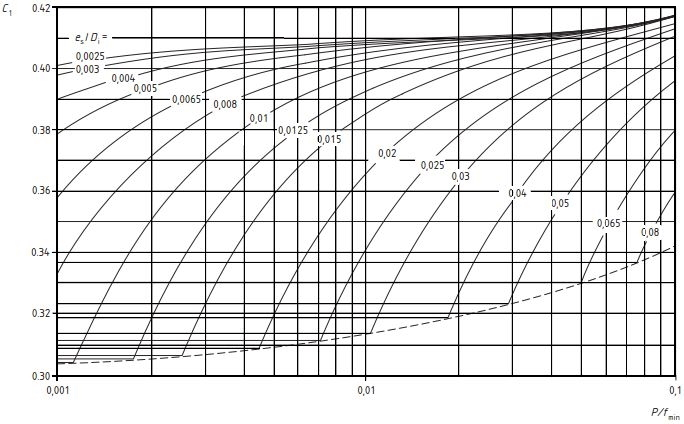
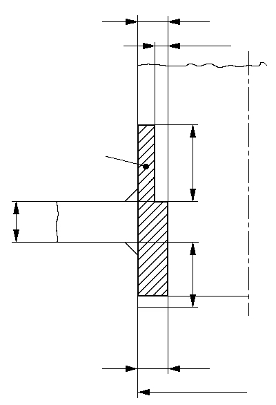
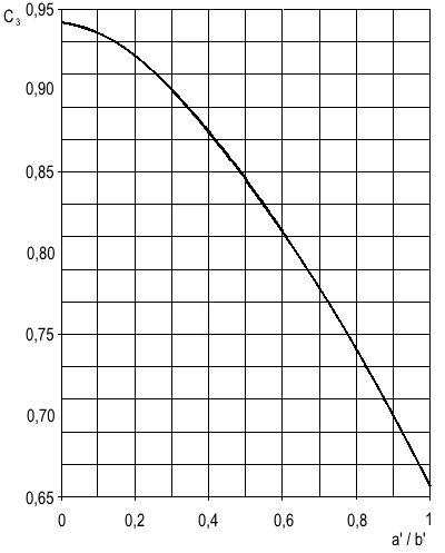
- Determine the calculation coefficient: The standard provides coefficients for each configuration that represent the clamping of the plate edge: for welded circular ends from the interaction of plate and shell, for bolted ends from gasket geometry and bolt loads, and for non-circular plates from the aspect ratio.
- Calculate the required end thickness: Using the coefficient, design pressure and allowable stress, the minimum required thickness of the plate is determined and supplemented by corrosion and manufacturing allowances. For welded ends, the standard additionally checks the stresses in the transition zone to the shell to prevent fatigue cracks at the edge of the end.
- Verify openings: For openings in the end, it is verified that the remaining cross-sections are sufficient. The standard uses a ligament-weakening approach that, depending on the size and location of the opening, requires an increased end thickness or reinforcement of the opening edge.
Input quantities
| Quantity | Symbol | Unit |
|---|---|---|
| Calculation according section | Abschnitt | – |
| Calculation similar | 10.5 | – |
| Design temperature | Td | °C |
| Test temperature | TTest | °C |
| Connected cylindrical shell | Zylinderschale | – |
| Hub thickness | g | mm |
| Off-set of wall center-lines of hub and cylindrical shell | bAZ | mm |
| erfüllen: | erfüllen: | – |
| überschreiten | überschreiten | – |
| 3 | 3 | – |
| berechnet | berechnet | – |
| Length of cylindrical shell, as shown in Figures 10.4-1 to 10.4-3 | lcyl | mm |
| Inside diameter of cylindrical shell | Di | mm |
| Analysis thickness of shell | es | mm |
| Distance between the external wall of an end and the weld on the shell | hW | mm |
| Distance of the centre of the radius of the relief groove from the outer surface of the end | hr | mm |
| Wert | Wert | – |
| 10.4-3) | 10.4-3) | – |
| 10.4-3) | 10.4-3) | – |
| Inside radius of the relief groove, see Figure 10.4 -3 | rd | mm |
| Calculate term with the coefficient C2 in equation 10.4-10 directly according to 10.4.6 | berechnen | – |
| Equivalent diameter of an end with a hub, see Figure 10.4-1 | Deq | mm |
| Nominal design stress operation | fd | N/mm² |
| Minimum design stress operation | fd, min | N/mm² |
Calculation options
Calculation according section
10.4 Unpierced circular flat ends welded to cylindrical shells · 10.5 Unpierced bolted circular flat ends · 10.6 Pierced circular flat ends · 10.7 Flat ends of non-circular or annular shape
Calculation similar
10.4.3 Flat ends with a hub · 10.4.4 Flat ends welded directly to the shell · 10.4.5 Flat ends with a relief groove · 10.5 Unpierced bolted circular flat ends
Connected cylindrical shell
Uniform thickness shell · Conical shell
Type of gasket
10.5.2 Flat end with a narrow-face gasket · 10.5.3 Flat end with a full-face gasket
Number of openings
One opening · Two openings
Type of first opening
Set-on nozzles · Set-in nozzles · No nozzles
Type of second opening
Set-on nozzles · Set-in nozzles · No nozzles
Type of end
10.4.3 Flat ends with a hub · 10.4.4 Flat ends welded directly to the shell · 10.4.5 Flat ends with a relief groove
Frequently asked questions
Why do flat ends come out so much thicker than dished ends?
A dished end carries pressure predominantly through membrane stresses in the shell surface, whereas a flat plate carries it in bending. The bending stress grows with the square of the diameter-to-thickness ratio, so flat ends require considerably greater wall thicknesses for the same pressure. Flat ends therefore pay off mainly at small diameters, moderate pressures, or when fabricating a dished end is uneconomical.
Can I use EN10 to calculate tubesheets of heat exchangers?
No. Tubesheets are supported by the tube bundle and at the same time weakened by the tube holes; their load-bearing behaviour differs fundamentally from that of an unstayed plate. Tubesheets are governed by EN 13445-3 clause 13 or the alternative method of Annex J (module ENAJ).
What does calculating with or without an edge moment mean for bolted ends?
If the gasket lies inside the bolt circle (narrow-face joint), the bolt load acting on the lever arm to the gasket produces an edge moment that increases the plate bending and can even govern the design in the bolting-up condition. With a full-face gasket, the gasket supports the plate all the way to the edge, so no significant edge moment develops and the required thickness is smaller.
What is a typical source of error when verifying welded flat ends?
Often only the centre of the plate is considered and the transition to the cylindrical shell is neglected. Yet high bending stresses occur precisely there, which can lead to cracks in the connecting weld under cyclic loading. EN 13445-3 therefore imposes minimum requirements on the connection geometry and limits the stresses in the transition zone; with frequent load cycles, an additional fatigue assessment to clause 17 or 18 is advisable.