Engineering task and calculation objective
Tubesheets are the most highly stressed component of a shell-and-tube heat exchanger: they carry the differential pressure between the tube side and the shell side, they are weakened by the drilled tube field, and with fixed tubesheets they are additionally loaded by the differential thermal expansion of tubes and shell. If you want to calculate a heat exchanger tubesheet to AD 2000 — the German pressure vessel code — you work with Merkblatt B5, which extends the flat plate rules to cover the specifics of the tube field.
The B51 module determines the required tubesheet thickness of heat exchanger tubesheets to AD 2000 B5. Compared with the base module B5, an additional equation for the ligament efficiency of the tube field is incorporated, taking into account tube pitch, tube lanes and the type of tube-to-tubesheet connection. Besides the tubesheet thickness, the tubes themselves are verified: actual tube force, unconstrained buckling length, slenderness ratio, and the actual and allowable buckling force of the tubes in compression.
The module covers fixed-tubesheet, floating-head and U-tube designs and — for fixed tubesheets — captures the additional tube force from thermal expansion as well as the thermal stresses in tubes and shell to AD 2000 S3/7. For the detailed verification of the axial forces of rigidly anchored tubesheets, the complementary B51A module is available.
Standard and calculation basis: AD 2000 B5: 2024-01
Calculation workflow
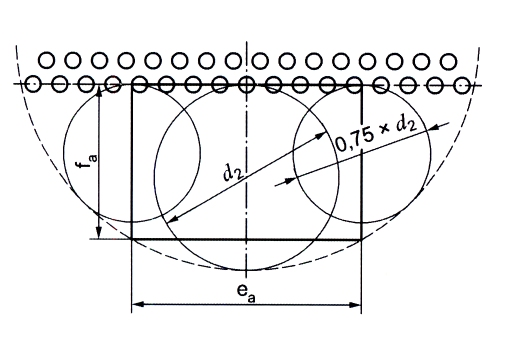
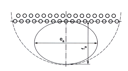
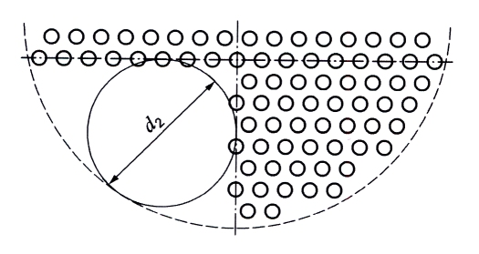
- Define the design type and geometry: First, the design type (fixed tubesheet, floating head, U-tube, expansion joint), tubesheet diameter, tube dimensions, tube pitch and any tube lanes are entered. From these the module calculates the ligament efficiency of the drilled field and the loaded area of the plate.
- Enter material properties for tubesheet, tubes and shell: For the tubesheet, the tubes and the shell, the nominal design stress, safety factor, modulus of elasticity and coefficient of thermal expansion at design temperature are required, each with the allowances for wall thickness undertolerance and corrosion/erosion.
- Calculate the required tubesheet thickness: From the design pressure, the governing diameter, the design coefficient, the ligament efficiency and the allowable stress K/S follows the required tubesheet thickness; it is compared with the as-built tubesheet thickness. The minimum weld throat thickness of the tube-to-tubesheet connection is also reported.
- Verify the tubes for tension and buckling: The loaded area yields the actual tube force per tube. For tubes in compression, the unconstrained buckling length, moment of inertia and slenderness ratio are determined and the actual buckling force is compared with the allowable buckling force; below the slenderness ratio limit, the buckling condition of the corresponding equation applies.
- Check thermal stresses and axial loads: For fixed tubesheets, the additional tube force from restrained thermal expansion is captured and the thermal stresses in tubes and shell are evaluated to AD 2000 S3/7. For shells or diameters above 1,200 mm, or for detailed restraint analyses, the module refers to B51A.
Input quantities
| Quantity | Symbol | Unit |
|---|---|---|
| Design diameter | d2 | mm |
| Design diameter shell side | D1 | mm |
| Outside tube diameter | da | mm |
| Inside tube diameter | di | mm |
| Bolt circle diameter | dt | mm |
| Mean gasket diameter | dD | mm |
| Pitch | t | mm |
| Design pressure tube side | pi | bar |
| Design pressure shell side | pu | bar |
| Design temperature | ϑ | °C |
| Safety factor | S | – |
| Nominal design strength of the tube sheet | KP | N/mm² |
| Rolling length | lw | mm |
| Number of tubes | n | – |
| Design factor | C | – |
| Modulus of elasticity of the tubes | E | N/mm² |
| Tubesheet thickness | s | mm |
| Rolling connection | FR | N |
| Weld thickness | g | mm |
| Allowable buckling force | FK | N |
| Tube material | WkR | – |
| Design factor | C1 | – |
| Characteristic value of the gasket | k1 | mm |
| Leak safety factor | SD | – |
Calculated results
| Quantity | Symbol | Unit |
|---|---|---|
| Weight of the tube bundle | G | kN |
| Moment of inertia | J | mm^4 |
| Unconstrained buckling length | lk | mm |
| Tubesheet thickness | s | mm |
| Rolling connection | FR | N |
| Loaded area | AR | mm² |
| Effective support area | AW | mm² |
| Weld thickness | g | mm |
| Ligament efficiency | v | – |
| Allowable buckling force | FK | N |
| Slenderness ratio | λ | – |
| Lower range limit of slenderness ratio | λ0 | – |
| Design factor based on pu | C4 | – |
| Design factor | C5 | – |
| Sheet thickness (floating) | sf | mm |
| Design pressure | p | bar |
| Sheet thickness (floating) | sb | mm |
| Design pressure of the floating sheet | pb | bar |
| Buckling force | FK | N |
| Tubesheet thickness | sa | mm |
| Additional thermal stress according to S3/7 Tube Lim. to diameter ≤ 1200mm | σR | N/mm² |
| Additional thermal stress according to S3/7 Shell Use B51A | σM | N/mm² |
| Required sheet thickness (governing equation | ) | – |
| Design factor floating sheet | C5f | – |
Frequently asked questions
What does the ligament efficiency of the tubesheet describe?
It captures the weakening of the plate by the drilled tube field as the ratio of the remaining load-bearing ligament to the tube pitch. The tighter the pitch, the smaller the coefficient and the thicker the required plate. Expanded or welded-in tubes can contribute to the load-bearing capacity depending on the type of connection; the B51 module contains an equation extended over the base module B5 for this purpose.
Why must the tubes be verified against buckling?
Under certain pressure and temperature combinations the tubes are subjected to axial compressive forces, for instance when the shell-side pressure dominates or the thermal expansion of the shell compresses the tubes. Slender tubes can then buckle before the allowable stress is reached. The governing quantities are the unconstrained buckling length between the baffles, the slenderness ratio and the allowable buckling force.
When is B51 sufficient, and when do I also need B51A?
B51 sizes the tubesheet thickness and performs the standard tube verifications including the simplified thermal stresses to S3/7. For rigid, firmly anchored tubesheets with a substantial temperature difference between tubes and shell, the mutual restraint must be calculated explicitly — that is what B51A does, via the compatibility of the length changes of bundle and shell.
What role does the tube lane play for the tubesheet thickness?
A tube-free lane (e.g. for pass partition plates in multi-pass operation) interrupts the regular drilled field and enlarges the locally effective plate span. It enters the calculation through the loaded area and the governing diameter and can increase the required tubesheet thickness significantly.