Engineering task and calculation objective
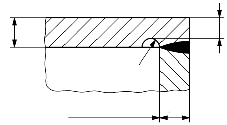
Module 12516D calculates bolted bonnets and covers made of flat plates to DIN EN 12516-2 — with or without a central bore or nozzle, and also as flat plates with an annular groove. In addition it covers the stuffing-box load per clause 11 of the standard, i.e. the forces introduced into the cover and the bolts via the gland follower.
To calculate flat plates to DIN EN 12516-2 means determining the required plate thickness from the design pressure, the allowable stress and the calculation coefficients (shape factors) of the respective support and loading situation. For plates with an opening or nozzle, a weakening factor increases the required thickness; the force ratio per Eq. 64 captures the influence of the additional forces from the bolting.
In practice this verification is needed for globe and gate valve covers, blanking plates and bonnets with a stem penetration — both for new designs and for re-rating for the test condition with the corresponding properties (strength value, safety factor and modulus of elasticity at test temperature).
Standard and calculation basis: DIN EN 12516-2: 2022-08
Calculation scope
- Flat plates with annular groove
- Gland flanges
- Bonnets and covers
Calculation workflow
- Select design and geometry: First the cover design is defined: flat plate with or without an annular groove, with or without a bore or nozzle. The inside diameter of the opening enters the calculation as a weakening.
- Determine material properties and allowances: For operation and test, the strength value, the safety factor and from these the allowable stress are determined; the manufacturing tolerance or forming allowance and the corrosion allowance are added to the calculated thickness.
- Determine forces and calculation coefficients: From the pressure force, the bolt force and the gasket geometry follows the force ratio per Eq. 64; the calculation coefficients (shape factors) capture the support conditions, the annular groove and the opening weakening of the plate.
- Calculate required plate thickness: With the allowable stress, the design pressure and the coefficients, the required plate thickness for the operating and test conditions is calculated and compared with the as-built thickness; for stuffing-box covers, the gland-follower forces per clause 11 are added.
Input quantities
| Quantity | Symbol | Unit |
|---|---|---|
| Design pressure | p | bar |
| Design temperature | t | °C |
| Type of cover (1/2/3) | Deckels | – |
| _Deckelart | _Deckelart | – |
| Material | Werkstoff | – |
| Nominal design strength operation | R | N/mm² |
| Safety factor operation | S | – |
| Allowable stress operation | f | N/mm² |
| Modulus of elasticity operation | E | N/mm² |
| Nominal design strength test | R' | N/mm² |
| Safety factor test | S' | – |
| Allowable stress test | f' | N/mm² |
| Modulus of elasticity test | E' | N/mm² |
| Mill tolerance | c1 | mm |
| Corrosion allowance | c2 | mm |
| Mean gasket diameter Fig. 26, 27, 29 or 31 | dD | mm |
| Gasket width | bD | mm |
| Safety factor of gasket | SD | – |
| Gasket compression factor m or. Q/p | Kompressionsfaktor | – |
| Maximum gasket compression | Qmax | MPa |
| Force ratio according eq. 64 | δ | – |
| Shape factor | Cx | – |
| Shape factor | Cy | – |
| Shape factor | Cz | – |
Calculation options
Belastung
Gasket with direct load (Fig. 26, 27, 29 or 31) · Gasket with no direct load (Fig. 28, 30 or 32)
Frequently asked questions
Why does an annular groove weaken the flat plate and how is this captured?
The annular groove — for a gasket, for example — reduces the load-bearing cross-section at a location of high bending stress. The standard captures this via a dedicated calculation coefficient or by verifying the remaining thickness at the groove bottom. A common mistake is to treat the groove merely as a corrosion allowance instead of accounting for it in the thickness formula.
How does a central bore or nozzle enter the calculation?
Openings increase the bending stresses in the plate. In the calculation this is captured via a coefficient that depends on the diameter ratio d/D and increases the required thickness compared with the solid plate. In addition it must be checked whether the nozzle attachment itself (weld, opening reinforcement) requires its own verification.
What must be considered for the stuffing-box load per clause 11?
The gland follower introduces the packing compression force into the cover via bolts. This force acts in addition to the internal pressure and depends on the required packing contact pressure. If it is neglected, the cover thickness and the bolt cross-section are undersized — especially for the high packing pressures of high-pressure valves.