Engineering task and calculation objective
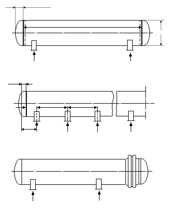
The S32 module performs the strength verification for horizontal vessels on saddle supports to AD 2000-Merkblatt S3/2 of the German AD 2000 pressure vessel code. Horizontal cylindrical vessels – storage tanks, heat exchangers, separators – usually rest on two saddle supports. The vessel acts as a beam under dead weight and filling while, at the same time, the saddles introduce high local forces into the shell. The module determines the longitudinal, circumferential and shear stresses at the endangered cross-sections and compares them with the allowable values.
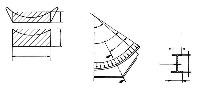
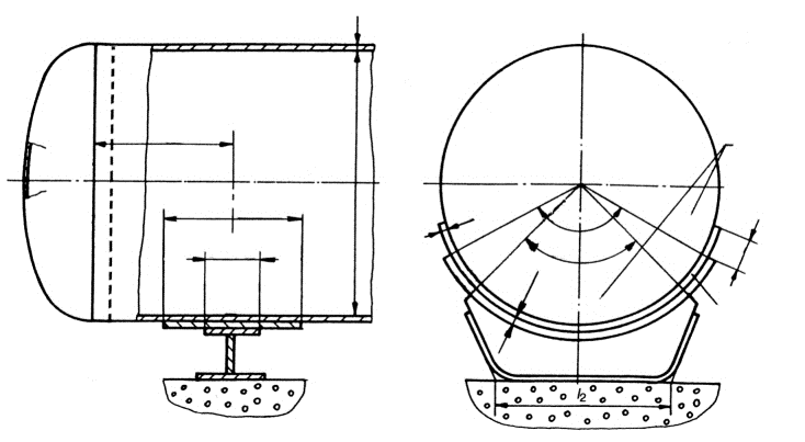
The governing locations are the mid-span of the vessel (maximum span moment), the saddle planes (support moment and shear force) and the saddle horn region, where the local circumferential bending reaches its maximum. The vessel can be stiffened on the inside or outside by stiffening rings or rest on the saddle via a support ring; wear plates between saddle and shell are likewise taken into account. Stiffeners fundamentally change the stress distribution and permit thinner vessel walls.
The verification to AD 2000 S3/2 complements the pressure calculation of the B-series Merkblätter: only the superposition of internal pressure (or vacuum) with the support loads shows whether wall thickness, saddle geometry and stiffening fit together. To this end, the module evaluates both the strength conditions and the geometrical conditions of the Merkblatt.
Standard and calculation basis: AD 2000 S3/2: 2004-02
Calculation workflow
- Enter vessel and saddle geometry: Diameter, wall thickness, length, head type, saddle distance from the vessel ends, saddle contact angle, and any existing wear plates, support rings or stiffening rings are entered. The module first checks the geometrical applicability conditions of the Merkblatt.
- Determine the loads: From dead weight, filling (operation and water fill during the hydrostatic pressure test) and any additional loads, the support reactions of the two saddles and the bending moment and shear force distributions of the vessel acting as a beam are obtained.
- Verify the longitudinal stresses: At mid-span and in the saddle planes, the longitudinal stresses from bending moment and internal pressure are superposed – checked against the allowable stress on the tension side, and additionally against the buckling limit of the shell on the compression side.
- Check shear and circumferential stresses at the saddle: The shear force generates shear stresses in the shell next to the saddle; at the saddle horn, local circumferential bending stresses arise, which frequently govern the design of unstiffened vessels. Stiffening rings or support rings take over this circumferential bending and relieve the shell.
- Evaluate strength and geometry conditions: All strength conditions of the governing cross-sections and the evaluated geometrical conditions are summarized and assessed; from this it follows whether wall thickness, saddle arrangement and stiffening are sufficient.
Input quantities
| Quantity | Symbol | Unit |
|---|---|---|
| Enclosing angle of the web plate | δ1 | ° |
| Enclosing angle of the saddle plate | δ2 | ° |
| Wall thickness without allowances | (e = se-c1-c2) e | mm |
| Vessel inside diameter | D | mm |
| Reinforcement plate projection | b3 | mm |
| Reinforcement plate thickness | ev | mm |
| Cylinder length | L | mm |
| Max. cylinder length (acc. Fig. 3) | Lmax | mm |
| Cantilever length of the cylinder | a1 | mm |
| Width of saddle support | b1 | mm |
| Width of reinforcement plate | b2 | mm |
| Final wall thickness | se | mm |
| Weld joint factor | v | - |
| Parameter K11 (acc. section 5.2.2.1) | K11 | - |
| Density of filling medium | Rf | kg/m³ |
| Design pressure | p | bar |
| Design temperature | T | °C |
| Material | Werkstoffnummer | - |
| Nominal design strength | K | N/mm² |
| Safety factor | S | - |
| Wall thickness manufacturing tolerance | c1 | mm |
| Corrosion / Erosion allowance | c2 | mm |
| Allowable design stress | f | N/mm² |
| Total vessel weight load | G | N |
Calculated results
| Quantity | Symbol | Unit |
|---|---|---|
| Enclosing angle of the saddle plate | δ2 | ° |
| Wall thickness without allowances | (e = se-c1-c2) e | mm |
| Vessel inside diameter | D | mm |
| Max. cylinder length (acc. Fig. 3) | Lmax | mm |
| Cantilever length of the cylinder | a1 | mm |
| Width of reinforcement plate | b2 | mm |
| Final wall thickness | se | mm |
| Weld joint factor | v | - |
| Parameter K11 (acc. section 5.2.2.1) | K11 | - |
| Design pressure | p | bar |
| Design temperature | T | °C |
| Material | Werkstoffnummer | - |
| Nominal design strength | K | N/mm² |
| Safety factor | S | - |
| Wall thickness manufacturing tolerance | c1 | mm |
| Corrosion / Erosion allowance | c2 | mm |
| Allowable design stress | f | N/mm² |
| Cantilever length of the tank | a3 | mm |
| Existing saddle load at load point | Fi | N |
| Existing moment at load point | Mi | Nmm |
| Existing transverse force at load pt. | Qi | N |
| Load point № | LNR | – |
| Allowable bending moment Calculate with LV module EN 16.14 | allM | Nmm |
| Allowable shear force Calculate with LV module EN 16.14 | allQ | N |
Calculation options
Option
4.1 Approximate strength proof and geometry acc. section 2.3.3 · 4.2 Actual forces and moments acc. AD S 3/2 · 4.3 Strength verification in the area between the saddles · 5.2.1 Cylindrical shell without reinforcing plate: Strength verification · 5.2.2.1 Simplified strength verification for reinforced cylindrical shell · 5.2.2.2 Cylindrical shell with reinforcement: Strength verification case 1 · 5.2.2.2 Cylindrical shell with reinforcement: Strength verification case 2 · 5.3.1 Strength verification of the vessel wall with stiffening ring · <b>5.3.2 Verification of the stiffening ring</b> · 6. Verification of the saddle
Frequently asked questions
Why is the saddle horn the most critical location?
At the end of the saddle contact angle, the supported shell passes abruptly into the unsupported region. The circumferential bending from the local load introduction concentrates there; the stresses at the saddle horn exceed the average shell stresses severalfold. Remedies are a larger contact angle, a wear plate with sufficient overhang, or stiffening rings in the saddle plane.
What influence does the saddle position relative to the heads have?
Saddles close to the dished ends exploit their stiffening effect: the head acts like a ring and reduces the circumferential bending in the saddle plane. If the saddles move towards mid-span, the span moment decreases, but the shell at the saddle loses the supporting effect of the head. As a proven compromise, the saddles are usually placed near the heads; the Merkblatt ties its formulas to corresponding geometrical conditions.
Does the water-fill load case for the pressure test have to be calculated separately?
Yes. During the hydrostatic pressure test, the vessel is completely filled with water – for gas or vapour vessels this can mean a multiple of the operating fill. At the same time, different safety factors apply to the test condition. This load case frequently governs the saddle and shell design even though it occurs only rarely.
When are stiffening rings required?
When the circumferential bending stresses at the saddle horn exceed the allowable values despite a wear plate, or when the shell is at risk of buckling in the unpressurized condition (vacuum, partial vacuum during draining). Internal or external stiffening rings in the saddle plane – or a support ring on which the vessel rests – stiffen the cross-section, take over the ring bending and permit considerably thinner vessel walls at large diameters.