Engineering task and calculation objective
This module calculates the heat loss of walls and pipework according to the VDI Heat Atlas (VDI-Wärmeatlas, 12th edition 2019). It covers insulated and uninsulated pipes and walls, exposed pipes indoors and outdoors – there with wind influence on the external heat transfer – as well as pipes laid within walls or buried in the ground. In addition to the heat flow, the calculation delivers the surface temperature, which governs personnel protection and the prevention of condensation.
Calculating the heat loss of pipework is a standard task when designing insulation in power plants, chemical plants, and building services: it is about energy costs, maintaining minimum temperatures at the consumer, protecting personnel from hot surfaces, and limiting the cool-down of media at standstill. The methodology corresponds to the resistance chain of internal heat transfer, conduction through the pipe wall and insulation layers, and external heat transfer by convection and radiation.
The calculation options select the installation case; from this follow the external heat transfer conditions to be applied – from natural convection in still indoor air, through a wind-exposed pipe outdoors, to heat dissipation into the surrounding masonry or soil.
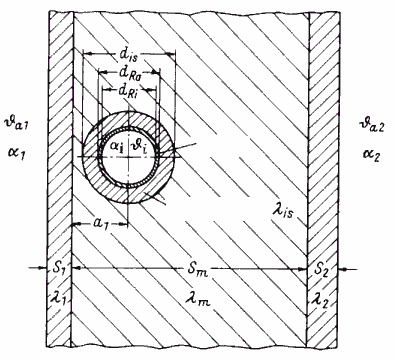
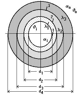
Standard and calculation basis: VDI-Wärmeatlas, 12. Auflage 2019
Calculation workflow
- Select the installation case and geometry: The calculation options define whether a plane wall or a pipe is present and how it is installed: exposed indoors, outdoors with wind, within a wall, or buried in the ground. Added to this are the pipe diameter, the insulation layer build-up, and the length or area.
- Specify temperatures and material properties: Required inputs are the medium or internal temperature, the ambient temperature, and the thermal conductivities of all layers at their respective mean temperatures. For insulating materials, the temperature dependence of the conductivity must be observed and, if necessary, accounted for iteratively.
- Determine the external heat transfer: The external heat transfer coefficient is composed of convection and radiation. For exposed installation indoors, natural convection at the surface is applied; outdoors, forced convection with the wind velocity; the radiation contribution depends on the emissivity of the cladding (bare sheet metal radiates considerably less than coated surfaces).
- Evaluate the resistance chain: Internal heat transfer, the conduction resistances of the pipe wall and insulation layers (for pipes, with the logarithmic diameter ratios), and the external transfer resistance are connected in series. This yields the heat flow, i.e., the heat loss per unit length of the pipe.
- Surface temperature and assessment: From the heat flow and the external transfer resistance, the surface temperature of the insulation follows. It is checked against touch protection limits or against the dew point (for cold service); if necessary, the insulation thickness is varied until the loss and the surface temperature meet the requirements.
Input quantities
| Quantity | Symbol | Unit |
|---|---|---|
| Inside temperature | ϑi | °C |
| Air temperature | ϑa | °C |
| Insulation thickness | s | m |
| Thermal conductivity of insulation | λ | W/(m·K) |
| Radiation coefficient | C | W/m²/K^4 |
| Wall temperature | ϑw | °C |
| Heat transfer coefficient outside | αa | W/(m²·K) |
| Heat loss per unit area | Q/A | W/m² |
| Wall surface | A | m² |
| Heat loss absolute | Q | W |
| Wind velocity | w | m/s |
| Inside heat transfer coefficient | αi | W/(m²·K) |
| Inside diameter of the pipe | d1 | m |
| Outside diameter of the pipe | d2 | m |
| Outside diameter of the insulation 1 | d3 | m |
| Outside diameter of the insulation 2 | d4 | m |
| £_1 | λ0 | W/(m·K) |
| £_2 | λ1 | W/(m·K) |
| £_3 | λ2 | W/(m·K) |
| Temperature difference | │ϑi-ϑa│ | °C |
| Auxiliary variable | D | m²·K/W |
| Heat loss per unit of length | Q/l | W/m |
| Pipe length | l | m |
| s_1 | s0 | m |
Calculation options
Calculation options
Insulated walls in inner rooms · Insulated piping (exposed) · Insulated Piping (in the wall)
Worked example
A DN 100 hot-water pipe (outside diameter 114.3 mm) with a medium temperature of 140 °C is insulated with 60 mm of mineral wool (λ = 0.045 W/(m·K)) and installed in a hall at 20 °C. The external heat transfer coefficient (convection and radiation) is 10 W/(m²·K); the resistances of the pipe wall and the internal heat transfer are negligibly small. Find the heat loss per unit length and the surface temperature of the insulation.
Given values
| Pipe outside diameter da | 114.3 mm |
| Insulation thickness s | 60 mm (Da = 234.3 mm) |
| Thermal conductivity of insulation λ | 0.045 W/(m·K) |
| Medium temperature ϑi | 140 °C |
| Ambient temperature ϑu | 20 °C |
| External heat transfer coefficient αa | 10 W/(m²·K) |
Solution
Conduction resistance of the insulation layer
Rλ = ln(Da/da) / (2 · π · λ) = ln(234.3/114.3) / (2 · π · 0.045)
Rλ = 0.7178 / 0.2827 = 2.539 (m·K)/W
External transfer resistance
Rα = 1 / (αa · π · Da) = 1 / (10 · π · 0.2343) = 0.136 (m·K)/W
Heat loss per unit length
ql = (ϑi − ϑu) / (Rλ + Rα) = 120 / (2.539 + 0.136) = 120 / 2.674
ql ≈ 44.9 W/m
Surface temperature of the insulation
ϑO = ϑu + ql · Rα = 20 + 44.9 · 0.136 ≈ 26.1 °C
The surface thus stays well below usual touch protection limits; the insulation resistance clearly dominates the resistance chain.
Result
| Heat loss q_l | ≈ 44.9 W/m |
| Surface temperature ϑ_O | ≈ 26.1 °C |
All values are illustrative. The applicable standard and project-specific boundary conditions remain authoritative.
Frequently asked questions
Since the surface temperature depends on the insulation thickness – why is iteration often necessary?
The external heat transfer coefficient itself depends on the surface temperature (natural convection and radiation are temperature-dependent), and the thermal conductivity of the insulating material depends on its mean temperature. Both quantities, however, are only known once the heat flow is fixed. The calculation therefore starts with estimated values and repeats the resistance chain until surface temperature and material properties are consistent – the module performs this iteration automatically.
What influence does wind have on the heat loss of an insulated pipe?
Wind increases the external heat transfer coefficient considerably – at a few m/s easily by a multiple compared with still air. For well-insulated pipes, however, the insulation resistance dominates the chain, so the total loss rises only slightly; the surface temperature drops much more markedly. For uninsulated or poorly insulated pipes, on the other hand, the wind feeds through almost fully into the loss.
Why does the emissivity of the cladding play such a large role?
At the outer surface, convection and radiation act in parallel. Bare aluminum sheet has an emissivity of around 0.05 to 0.1, whereas galvanized or coated sheet has 0.3 to 0.9. At moderate excess temperatures, the radiation contribution in still air can reach the same order of magnitude as the convection – so the choice of cladding noticeably changes the heat loss and, above all, the surface temperature.
Is there an insulation thickness beyond which more insulation is harmful?
For pipes, the outer surface grows with the insulation thickness. Below the so-called critical diameter (ratio of insulation conductivity to external heat transfer coefficient), additional insulation can theoretically increase the loss. In practice, this is only relevant for very thin pipes or cables; for usual pipe dimensions and insulating materials, the critical diameter lies far below the pipe diameter, so more insulation always reduces the loss – only with diminishing returns.