Engineering task and calculation objective
This module calculates the heat transfer and pressure drop in the subcooling zone of a shell-side condenser according to the VDI Heat Atlas (VDI-Wärmeatlas, 11th edition 2013, sections G8 and L1.5). In many condensers, the condensate is deliberately cooled below saturation temperature after condensation is complete — for example, to prevent cavitation in the downstream condensate pump or to rule out flashing in the condensate line. Hydraulically, the subcooling zone behaves like a baffled tube bundle in cross flow carrying single-phase condensate.
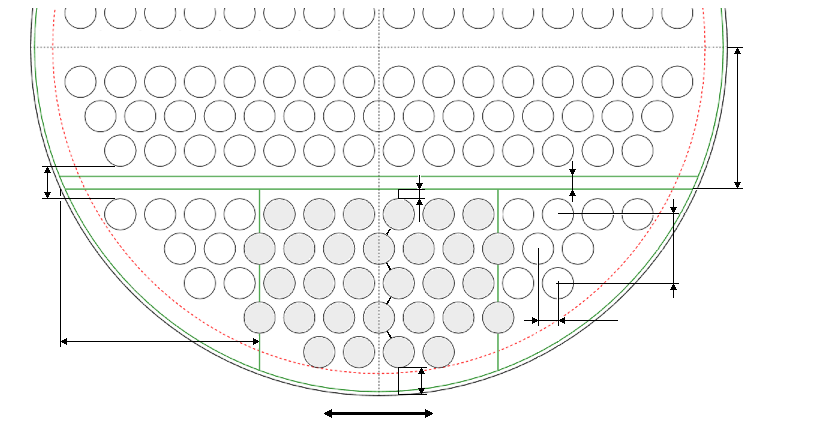
The calculation follows the VDI Heat Atlas cell model for tube-filled shell spaces: the effective heat transfer coefficient is determined from the bundle geometry — tube pitch, transverse, longitudinal, and diagonal pitch ratios — together with the clearance areas between tubes and baffle holes, baffle and shell. Leakage and bypass streams flowing past the bundle are captured through leakage-flow, bypass-flow, and geometry factors, because they reduce the heat transfer significantly compared with an ideal tube bundle in pure cross flow.
If you want to calculate condensate subcooling in a condenser, this module delivers the mean Nusselt number, the mean heat transfer coefficient, and the pressure drop in the subcooling zone — the basis for splitting the heat transfer surface between the condensing and subcooling sections in heat exchanger design.
Standard and calculation basis: VDI-Wärmeatlas, 11. Auflage 2013, G8 & L1.5
Calculation workflow
- Define operating data and condensate properties: Starting from the mass flow or volume flow and the condensate temperature at inlet and outlet, the mean condensate temperature is formed. Density, specific heat capacity, thermal conductivity, kinematic and dynamic viscosity, and the Prandtl number are evaluated at this temperature; in addition, viscosity and Prandtl number at the tube wall temperature are required for the wall correction.
- Capture bundle and shell geometry: The tube pitch and tube layout yield the transverse, longitudinal, and diagonal pitch ratios as well as the void fraction of the bundle. For the flow model, the smallest cross-sectional area for the cross flow, the reference cross-sectional area, the bypass area, and the sum of all clearance areas (tube/baffle hole, baffle/shell, longitudinal baffle/baffle) are determined.
- Form the reference velocity and Reynolds number: The volume flow and the narrowest cross section of the cross-flow zone give the mean velocity, from which the reference velocity for the Reynolds number and the Reynolds number of the tube bundle in the cross-flow zone follow.
- Calculate the ideal bundle heat transfer: Using the Reynolds and Prandtl numbers, the mean Nusselt number of the ideal tube bundle in cross flow is calculated from the correlations for tube bundles in cross flow, including the arrangement factor for the tube layout and the correction factor for the number of tube rows.
- Correct for leakage and bypass streams: The ideal heat transfer is reduced by the geometry factor, the leakage-flow factor, and the bypass-flow factor. The result is the mean heat transfer coefficient of the subcooling zone, referred to the total surface area of all tubes.
- Determine the pressure drop of the subcooling zone: Analogously, the pressure drop in the subcooling zone is calculated according to section L1.5 from the drag coefficient of the bundle and the correction factors for leakage and bypass flow.
Input quantities
| Quantity | Symbol | Unit |
|---|---|---|
| Typ | Typ | – |
| Anordnung | Anordnung | – |
| Di | Di | m |
| DB | DB | m |
| dS | dS | m |
| da | da | m |
| s1 | s1 | m |
| s2 | s2 | m |
| D1 | D1 | m |
| H | H | m |
| dB | dB | m |
| S | S | m |
| SE | SE | m |
| rLL | rLL | m |
| tLL | tLL | m |
| bRG | bRG | m |
| n | n | – |
| nF | nF | – |
| nR | nR | – |
| nRF | nRF | – |
| nS | nS | – |
| nW | nW | – |
| nU | nU | – |
| nE | nE | – |
Calculated results
| Quantity | Symbol | Unit |
|---|---|---|
| w | w | m/s |
| Re\u03c8,l | Reψ,l | – |
| Nu0,AW | Nu0,AW | – |
| \u03b1a | αa | W/(m²·K) |
| \u0394Ptot | ΔPtot | Pa |
| Re | Re | – |
| we | we | m/s |
Calculation options
Typ
Geradrohr-WÜ · U-Rohr-WÜ
Anordnung
versetzt · fluchtend
Frequently asked questions
Why is the condensate subcooled at all?
Deliberate subcooling by a few kelvin prevents the condensate from flashing in the suction line of the condensate pump or downstream of control valves, where it would cause cavitation or vapor hammer. In addition, a defined degree of subcooling may be required by the process, for example when the condensate is processed further directly. However, the subcooling zone ties up heat transfer surface with a markedly poorer heat transfer coefficient than condensation itself and should therefore be sized deliberately.
Why are leakage and bypass streams so important in the calculation?
In real equipment, a considerable share of the medium flows past the actual bundle — through the clearances between tubes and baffle holes, between baffle and shell, and through the bypass gap between bundle and shell. These partial streams contribute very little to heat transfer. Without the correction factors of the VDI Heat Atlas, the heat transfer coefficient would be significantly overestimated — errors of 20 to 40 % are not uncommon without the leakage correction.
Does the calculation also apply to the condensing zone of the apparatus?
No. The module deals exclusively with the single-phase subcooling zone, in which fully condensed medium flows as liquid across the bundle. The heat transfer during film condensation on the bundle is calculated separately with the condensation sections of the VDI Heat Atlas (section J); in equipment design, the surface areas of the two zones are added.
What role does the tube wall temperature play in the input?
The fluid properties are always evaluated at the mean condensate temperature. Since the viscosity of liquids is strongly temperature-dependent, the VDI Heat Atlas additionally corrects the Nusselt number with the ratio of the Prandtl numbers or viscosities at the mean fluid temperature and at the wall temperature. This is why dynamic viscosity and Prandtl number must also be entered at the tube wall temperature.