Engineering task and calculation objective
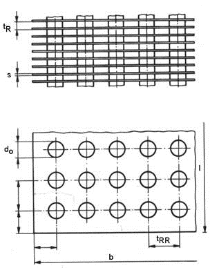
The module calculates heat transfer on finned tubes and finned tube bundles in cross-flow according to chapter M1 of the VDI Wärmeatlas (VDI Heat Atlas, 12th edition 2019). From the mass flow rate, mean temperature and the bundle geometry — tube pitch transverse to the flow direction, number of tubes side by side, number of tube rows, finned tube length, and in-line or staggered tube arrangement — the heat transfer coefficient and the effective duty of the finned surface are determined.
Finned tubes are used wherever a medium with poor heat transfer flows on one side of the heat exchanger, typically air or other gases: air-cooled condensers and dry coolers, economizers, charge air coolers or heating coils. The enlarged outer surface compensates for the low gas-side heat transfer coefficient. To calculate heat transfer on finned tubes, the fin efficiency must be considered in addition to the Nusselt correlation, because the fin temperature drops toward the fin tip.
The module reproduces the complete calculation procedure of the VDI Wärmeatlas, including the corrections for a small number of tube rows and for staggered arrangements in which every second row contains one tube fewer.
Standard and calculation basis: VDI-Wärmeatlas, 12. Auflage 2019
Calculation workflow
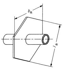
- Define the geometry of the finned tube bundle: Tube and fin dimensions as well as the bundle data are entered: tube pitch transverse to the flow direction, number of tubes side by side, number of tube rows, finned tube length, duct width and cover strips per side. The arrangement (in-line or staggered, possibly with one tube fewer in the staggered rows) determines the narrowest flow cross-section.
- Determine the flow conditions in the narrowest cross-section: From the mass flow rate and the cross-section blocked by tubes and fins, the governing velocity in the narrowest cross-section is calculated. With the physical properties at mean temperature, the Reynolds number referred to the tube outside diameter follows from this.
- Evaluate the Nusselt correlation for finned tubes: The correlation according to VDI Wärmeatlas M1 gives the Nusselt number as a function of Reynolds number, Prandtl number and the ratio of total surface to bare tube surface; the constants differ for in-line and staggered arrangements. For few tube rows, a row number factor is applied.
- Calculate the fin efficiency: Since the fin temperature decreases toward the tip, the fin efficiency is determined from the fin geometry, the thermal conductivity of the fin material and the heat transfer coefficient. From this follows the apparent heat transfer coefficient referred to the total surface.
- Assess heat duty and pressure drop: With the apparent heat transfer coefficient, the total surface and the temperature difference, the transferable duty is determined. In parallel, the gas-side pressure drop of the bundle must be checked, since it determines the fan power.
Input quantities
| Quantity | Symbol | Unit |
|---|---|---|
| Fin outside diameter | D | m |
| Outside tube diameter | da | m |
| Fin thickness | s | m |
| Free distance between the fins | a | m |
| Inside tube diameter | di | m |
| Fin pitch | tR | m |
| Tube pitch (crosswise) | tRR | m |
| Width | B | m |
| Finned tube length | H | m |
| Number of tubes (side by side) | RN | - |
| Number of tube rows | RR | - |
| Flow area | A0 | m² |
| Number of fins per tube | RiR | - |
| Fin area per tube | AR | m² |
| Free external surface per tube | AG | m² |
| Bare area per tube | AG0 | m² |
| Total external surface per tube | A | m² |
| Internal surface per tube | Ai | m² |
| Density | ρ | kg/m³ |
| Dynamic viscosity | η | mPa·s |
| Prandtl number | Pr | - |
| Thermal conductivity | λ | W/(m·K) |
| Heat transfer coefficient tube + fin | αR | W/(m²·K) |
| Thermal conductivity of fin material | λR | W/(m·K) |
Calculated results
| Quantity | Symbol | Unit |
|---|---|---|
| Inlet velocity ist based on mean density | w0 | m/s |
| Velocity in the narrowest cross-section | weT | m/s |
| Correction factor for weT | Tk | - |
| Reynolds number | Re | - |
| Heat transfer coefficient tube + fin | αR | W/(m²·K) |
| Fin efficiency | ηR | - |
| Virtual heat transfer coefficient | αs | W/(m²·K) |
| Reynolds number | Re | - |
Calculation options
Tube arrangement (aligned / staggered)
aligned · staggered
Staggered rows with one tube less than base rows?
No · Yes
Considering temperature dependence of viscosity ?
No · Yes
Fluid liquid /gaseous?
Liquid · 1
Frequently asked questions
Why can the heat transfer coefficient not simply be applied to the entire fin surface?
The fin is not an isothermal component: toward the fin tip, the temperature difference to the gas decreases, so the outer surface portions transfer less heat. This is captured by the fin efficiency, which for typical air cooler fins lies between about 0.7 and 0.95. If it is ignored, the duty of the bundle is systematically overestimated — the taller and thinner the fin and the better the heat transfer, the more so.
In-line or staggered tube arrangement — which is better?
Staggered arrangements force stronger deflection of the flow, deliver higher heat transfer coefficients and are preferred for finned tube bundles. The price is a higher pressure drop. In-line arrangements are more streamlined, but tend to form continuous flow lanes between the tube rows and thus poorer surface utilization. The module accounts for the arrangement through different correlation constants.
What influence does the number of tube rows have?
The correlations apply to bundles with many tube rows in which turbulence is fully developed. With fewer than about five rows, the mean heat transfer is lower, because the first rows benefit from the undisturbed inflow and the wake turbulence is not yet present; this is corrected by a row number factor. Very shallow bundles with only one or two rows must be assessed separately.
How does fouling affect finned tubes?
On the gas side, dust and fibers deposit preferentially in the spaces between the fins; this increases the pressure drop and often reduces the free cross-sectional area more severely than the pure heat transfer resistance. The design should provide fouling margins and sufficient fin pitch (cleanability), especially with dust-laden ambient air or flue gases.