Engineering task and calculation objective
The EN16.09 module calculates horizontal cylindrical vessels on ring supports to DIN EN 13445-3, Clause 16.9. With this type of support, the vessel weight is not introduced into the shell directly via saddles but via support rings welded to the shell on the inside or outside. The rings themselves rest on saddles or support feet. This design is chosen when the shell itself is too thin for a direct saddle support, or when defined bearing points are needed, for example on transport vessels and silo trucks.
The calculation verifies both the support ring and the adjacent shell: the ring is loaded by the support reactions in bending, normal force and shear force, and the shell by the local introduction of the ring forces. The inputs are the load case, the type of support, the ring profile, the position of the bearings, and the design pressure and design temperature; among the results, the module delivers the horizontal and vertical forces on the ring and checks the conditions of applicability of the standard.
This allows horizontal vessels with support rings to be calculated fully to the European pressure vessel code – an alternative to the classic saddle check per Clause 16.8 when its prerequisites are not met.
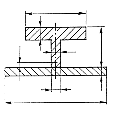
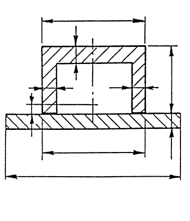
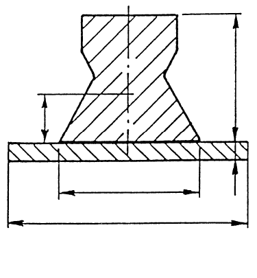
Standard and calculation basis: DIN EN 13445-3/16.9: 2018-12
Calculation workflow
- Define load case and support: First, the governing load case (operation, test, transport), the type of support of the rings (saddles or support feet), their position on the circumference, and the number of bearing points are defined. The design pressure and design temperature of the vessel are added.
- Record ring profile and geometry: The profile of the support ring is selected and entered with its cross-section properties, along with whether the ring is welded to the shell on the inside or outside. From the vessel diameter, wall thickness and ring dimensions, the stiffness relations between ring and shell are obtained.
- Check the conditions of applicability: The standard ties the method to geometric conditions of applicability, for example on the ratios of ring spacing, diameter and wall thickness. The module evaluates these conditions and reports when the range of application is exceeded.
- Calculate bearing forces and ring section forces: From the vessel weight, the contents and external loads, the horizontal and vertical forces at the bearing points of the ring are determined. From these follow the internal forces in the ring: bending moments, normal and shear forces around the circumference.
- Perform the stress checks for ring and shell: The stresses in the ring profile and the local stresses in the shell at the ring attachment are compared with the allowable values – superimposed on the stresses from the design pressure. If necessary, the profile, the ring position or the bearing arrangement is adjusted.
Input quantities
| Quantity | Symbol | Unit |
|---|---|---|
| Support | Lagerung | – |
| Type of profile | Profilform | – |
| Design pressure | P | MPa(p) |
| Design temperature | T | °C |
| Nominal wall thickness of shell | se | mm |
| Inside diameter of shell | Di | mm |
| Web thickness of ring section | e1 | mm |
| Total height of ring cross section | h1 | mm |
| Contact width of ring and shell | t | mm |
| Angle of support | δ | ° |
| Radius of neutral axis of ring cross section | RR | mm |
| Total width of ring cross section | b2 | mm |
| Flange thickness of ring section | e2 | mm |
| Distance from neutral axis of ring cross section to shell | hg | mm |
| Condition of applicability | Anwendungsbedingung | – |
| Condition of applicability | Anwendungsbedingung | – |
| Material | Schale | – |
| Mill tolerance | c1S | mm |
| Corrosion allowance | c2S | mm |
| Strength | KSOp | N/mm² |
| Strength | KSTest | N/mm² |
| Safety factor | SOpS | - |
| Safety factor | STestS | - |
| Nominal design stress | fS | N/mm² |
Calculated results
| Quantity | Symbol | Unit |
|---|---|---|
| Condition for using any ring profile | Ringprofils | – |
| Utilization of ring support | U | -- |
| Strength condition | Festigkeitsbedingung | - |
| Strength condition (shell) | Schale | – |
Calculation options
Support
Saddle · Legs
Type of profile
Ring · T profile · U profile · Any profile
Position
Inside · Outside
Frequently asked questions
When should a ring support be preferred to the classic saddle support?
The saddle support per Clause 16.8 introduces the bearing forces directly into the shell and requires sufficient shell stiffness. For thin-walled vessels, large diameters, high additional loads, or when the saddle checks do not work out, a welded-on support ring distributes the loads evenly around the circumference. Ring supports are also common for transport vessels with defined bearing points and for insulated vessels where saddles are unfavourable.
Does it matter whether the ring is welded on the inside or the outside?
Yes. Internal rings keep the outer contour clear (important with insulation or heating jackets) but reduce the usable cross-section and can cause cleaning problems where they contact the product. External rings are easier to access during fabrication. Structurally, the attachment differs: the eccentric load transfer between the ring centroid and the shell mid-surface affects the local shell stresses differently depending on the arrangement.
Which load cases are typically governing?
Besides the operating condition with contents and pressure, the governing cases are often the pressure test with water filling (highest weight) and transport or erection conditions in which the vessel is unpressurized and dynamic factors act on the weight. The module supports the load case selection; each condition must be verified with the corresponding allowable stresses.