Engineering task and calculation objective
Every branch and every nozzle weakens the pressure-bearing wall of a pipeline. This module calculates openings and branch connections in metallic industrial piping to DIN EN 13480-3, clause 8: single openings, adjacent (mutually interacting) openings, tees, Y-branches, and branches with rib-type reinforcement.
In piping engineering, this calculation is needed whenever a branch is added, a forged or welded tee has to be verified, or a reinforcement has to be sized — for instance by an increased wall thickness of the run pipe or branch pipe, by a reinforcing pad, or by ribs. The basis is the pressure-area method: the pressure-loaded areas are balanced against the load-bearing cross-sectional areas of run pipe, branch and reinforcement.
Besides the strength condition, the module also checks the geometric limits of applicability of the code — such as diameter and wall thickness ratios and the contributing lengths, which enter via the height and projection variables of nozzle and reinforcement — and states for each load case whether both conditions are satisfied.
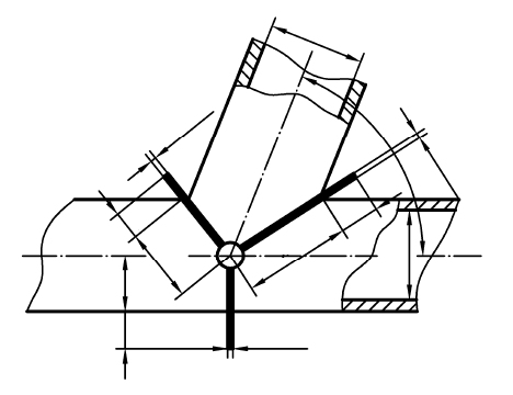
Standard and calculation basis: DIN EN 13480-3/8: 2017-12
Calculation scope
- Isolated openings and Y-branches
- Adjacent openings
- Triform reinforced branches
Calculation workflow
- Define design type and geometry: The type is selected via the design-type variable: perpendicular or oblique single branch, Y-branch, adjacent openings, or rib-reinforced branch. Then the diameters and wall thicknesses of run pipe and branch as well as the heights and projections of the contributing sections (internal projection, nozzle height, reinforcement dimensions) are entered.
- Assign load case and material properties: For each load case, design pressure and design temperature are specified; from these the allowable stresses of the materials involved are derived. If run pipe, nozzle and reinforcement have different strengths, the code credits the weaker parts only with their actually usable allowable stress.
- Determine pressure-loaded and load-bearing areas: Following the pressure-area method, the pressure-loaded areas Ap of run pipe and branch and the stress-bearing cross-sectional areas Aσ within the contributing lengths are determined. Only material within these code-limited lengths — controlled via the height and projection of nozzles and reinforcements — may be credited as reinforcement.
- Evaluate the strength condition: The strength condition compares the loading of the load-bearing cross-sections resulting from the pressure with the allowable stresses. The module explicitly states whether the strength condition is satisfied; if not, the reinforcement (wall thickness, pad, rib) can be enlarged and the verification repeated immediately.
- Check geometric conditions and adjacency: Finally, the geometric limits of applicability are checked: allowable diameter ratios, wall thickness ratios and — where there are several openings — the ligament distance. If two openings lie closer together than their contributing zones extend, they must be verified jointly as adjacent openings.
Input quantities
| Quantity | Symbol | Unit |
|---|---|---|
| Load case | case | – |
| Load case | text | – |
| Creep range, if | t | °C |
| Operating pressure | P | MPa |
| Designation | shell | – |
| Thickness allowance | δe | mm |
| Corrosion allowance | c | mm |
| Manufacturing allowance | δm | mm |
| Total allowances | Σ(δ) | mm |
| The strength condition is | = ≤1 | – |
| Strength | KTest | MPa |
| Safety | STest | – |
| Strength | KOp | MPa |
| Safety | SOp | – |
| Type of nozzle set-in=2, set-on=3 | (1-6) | – |
| Type of nozzle | text | – |
| Isolated opening in creep range | 8.4.3 di/Di ≤ 0.8 | mm |
| Allowable stress | f | MPa |
| Outside diameter of shell | De | mm |
| Inside diameter of shell | Di | mm |
| with a connection diameter | Dc = | mm |
| Outside diameter of opening, nozzle or ring | d,deb | mm |
| Inside diameter of nozzle | di | mm |
| Final nozzle (ring) thickness acc. drawing | eord,b | mm |
Calculated results
| Quantity | Symbol | Unit |
|---|---|---|
| Load case | text | – |
| Creep range, if | t | °C |
| Operating pressure | P | MPa |
| The strength condition is | = ≤1 | – |
| Isolated opening in creep range | 8.4.3 di/Di ≤ 0.8 | mm |
| Inside diameter of shell | Di | mm |
| Inside diameter of nozzle | di | mm |
| Calculation thickness without allowances | eab | mm |
| Final thickness without allowances | eap | mm |
| Accountable thickness | Min. (eap,eas) (8.4.3-5) eapl | mm |
| Reduced nozzle length outside shell | Min(lb,lbo) l'b | mm |
| Reduced nozzle length inside shell | Min(lbi,lbo/2) l'bi | mm |
| Max. supporting length of nozzle outside shell | lbo | mm |
| Max. supporting length of nozzle inside shell | lbo/2 | mm |
| Supporting length of cylindrical connection | lcyl | mm |
| Effective supporting length | Min(lsv,ls) l's | mm |
| Accountable width | Min. (lp,ls) l'p | mm |
| Maximum supporting length | ls | mm |
| Cross-sectional area of nozzle | Afb | mm² |
| Cross-sectional area | Afp | mm² |
| Cross-sectional area of shell | Afs | mm² |
| Cross-sectional area of fillet weld | Afw | mm² |
| Pressure loaded area of shell | Aps | mm² |
| Pressure loaded area of nozzle | Apb | mm² |
Calculation options
External cover External cover excludes a cover inside the shell
Yes · No
Type
Isolated openings in spherical and cylindrical shells · Multiple openings in spherical and cylindrical shells · Branches with rip-shaped reinforcement
Frequently asked questions
When must two openings be calculated jointly as adjacent openings?
If their contributing regions in the run pipe overlap, the wall material between the openings is no longer fully available to both. The code defines a distance criterion based on the contributing lengths; if it is not met, the ligament between the openings must be verified in a joint area comparison. Only with sufficient distance may the openings be treated as single openings.
Which types of reinforcement are possible for branches and what has to be observed?
Common options are an increased wall thickness of the run pipe, a thick-walled or extended nozzle (also with an internal projection), welded-on reinforcing pads, and rib-type reinforcements. Reinforcement material is only effective within the contributing lengths; material further away is disregarded. With reinforcing pads, attention must also be paid to temperature limits and thermal expansion compatibility with the run pipe.
Does the calculation also cover external loads and moments on the branch?
No. Clause 8 of DIN EN 13480-3 verifies the opening reinforcement against internal pressure. Forces and moments from the piping analysis — thermal expansion, dead weight, dynamic loads — must additionally be covered by the flexibility analysis verifications of the code (clause 12) with the associated stress intensification factors of the branch.
What is the difference between a tee to a product standard and a calculated branch?
Standardized fittings qualified by proof testing (e.g. to EN 10253 with a demonstrated design pressure rating) may be used without individual verification. A branch welded up from pipes, or a tee without a documented pressure rating, must instead be verified by calculation to clause 8 — which is exactly what this module does.