Engineering task and calculation objective
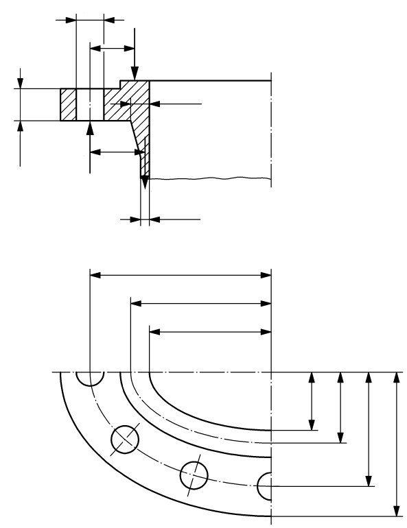
Module 12516B calculates oval and rectangular flanges, their bolting and self-sealing closures on valve bodies to DIN EN 12516-2. Such non-circular flange shapes are typical for bonnet and cover joints of gate valves and globe valves where the available space does not permit circular flanges, or where oval covers with only two bolts are used.
Anyone who wants to calculate such a joint to DIN EN 12516-2 must first determine the minimum bolt forces for the operating, test and bolting-up conditions from the internal pressure force and the gasket force, and then verify that the flange resistances in the governing cross-sections can carry the resulting moments. The module performs both verifications: the bolt calculation with the gasket parameters (effective gasket width, design factor, minimum gasket contact pressure) and the flange verification with the moments per Eq. 207 and Eq. 210 of the standard.
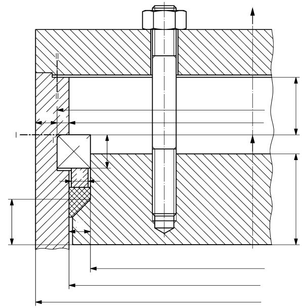
For self-sealing closures, whose sealing action increases with internal pressure, different force assumptions apply; the module covers this design as well.

Standard and calculation basis: DIN EN 12516-2: 2022-08
Calculation scope
- Self-sealing closures
- Bolts
- Rectangular or square flanges
- Oval flanges with more than two bolts
- Oval flanges with two bolts
Calculation workflow
- Define load case and design data: For the operating or test load case, the design pressure or test pressure and the design temperature are specified. From the material follow the strength values K, the safety factors and, from these, the allowable stresses for the operating, test and bolting-up conditions.
- Enter gasket parameters: For the selected gasket the outside and inside diameters, the effective gasket width, the design factor and the minimum gasket contact pressure are entered; from these the module determines the gasket force required in operation and the pre-deformation (seating) force.
- Determine bolt forces: The internal pressure force and the gasket force yield the minimum bolt forces for the operating condition, gasket seating and the bolting-up condition. They are the basis for sizing the bolts with the safety factor per clause 10.3.1.
- Calculate moments in the flange cross-sections: With the bolt forces F_SB (operation/test) and F_S0 (bolting-up), the bending moments are formed per Eq. 207 for cross-section I-I and per Eq. 210 for cross-section II-II.
- Check strength conditions: The required flange resistances derived from the moments are compared with the available resistances per Eq. 209 and Eq. 211. The joint is verified when all strength conditions are satisfied in every load condition.
Input quantities
| Quantity | Symbol | Unit |
|---|---|---|
| Calculation pressure | p | N/mm² |
| Outside diameter | dA | mm |
| Calculation pressure | p | bar |
| Mechanical strength K | K K' | N/mm² |
| Safety factor | S | – |
| Test pressure | p' | N/mm² |
| Gasket compression factor | m | - |
| Minimum gasket compression | σvu | N/mm² |
| Final flange height | hF | mm |
| Safety factor | S | – |
| Test pressure | p' | bar |
| Mechanical strength K | K K' | N/mm² |
| Bolt circle diameter | dt | mm |
| Mean gasket diameter | dD | mm |
| Material | WNr | – |
| Distance from centre of gravity 1 | s1 | mm |
| Calculation temperature | T | °C |
| Distance from centre of gravity 2 | s2 | mm |
| Partial area | A1 | mm² |
| Inside diameter | d0 | mm |
| Partial area (A2=A1) | A2 | mm² |
| Distance | a | mm |
| Length | b | mm |
| Internal pressure load | Fp | N |
Calculated results
| Quantity | Symbol | Unit |
|---|---|---|
| Bolt diameter (operation) | ds0 | mm |
| Bolt diameter (test) | ds0' | mm |
| Bolt diameter (installation) | ds0'' | mm |
| Design allowance of bolts (operation) | c | mm |
| Required bolt diameter | ds = dk | mm |
| Diameter of bolts + c (operation) | Zuschlag | mm |
Frequently asked questions
What is special about oval flanges with only two bolts?
With two bolts, the bolt forces act on the major axis of the oval, and the flange is loaded like a beam on two supports with the gasket and pressure forces between them. DIN EN 12516-2 provides dedicated equations for this case, which differ significantly from the calculation of oval flanges with several bolts; the two designs must not be confused.
How does a self-sealing closure work and what changes in the calculation?
In a self-sealing closure, the internal pressure presses the cover or the seal against the seat, so the sealing action increases with pressure. The bolts essentially only have to secure the bolting-up condition and the initial seating pressure, not the full pressure force in operation. The force assumptions of the standard therefore differ fundamentally from the classic bolted flange joint where the main force path passes through the gasket.
Why must the bolting-up condition be verified separately?
In the bolting-up condition the full bolt preload acts on flange and gasket without any relieving internal pressure. For soft gaskets with a high seating force, this condition can produce a larger flange moment than the operating condition; the standard therefore requires comparing both moments against the respective allowable stresses.
Where do the gasket parameters for the calculation come from?
The design factor and the minimum gasket contact pressure are gasket-specific parameters tabulated in the standard or provided by the gasket manufacturer. They depend on the gasket material and type. If generic values are used instead of manufacturer data, they should be chosen conservatively, since contact pressures set too low lead to leaking joints and values set too high to overloaded ones.