Engineering task and calculation objective
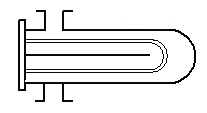
The WTS module package performs the thermal and hydraulic design of shell-and-tube and double-pipe heat exchangers according to the VDI Heat Atlas. It covers gaseous and liquid media as well as condensing pure substances, and supports the common construction types — fixed tubesheet, floating head and U-tube exchangers — with segmental baffles, disc-and-doughnut baffling, no-tubes-in-window design, finned tubes and multiple tube-side and shell-side passes. Add-on modules extend the functionality, for example with additional process cases.
Designing a shell-and-tube heat exchanger means solving two coupled problems simultaneously: the overall heat transfer from the tube side to the shell side, and the pressure drops on both sides. On the shell side this is demanding, because the baffles route the flow across and along the bundle, while leakage and bypass streams (clearances between tubes and baffles, between baffle and shell, bypass around the bundle) reduce the effective cross-flow. The VDI Heat Atlas captures these effects with a cell or stream analysis method — the basis for designing coolers, heaters and condensers in process plant engineering.
Standard and calculation basis: VDI Wärmeatlas
Calculation workflow
- Problem definition and heat balance: From the mass flows, inlet and outlet temperatures and fluid properties of both media, the heat duty to be transferred is balanced; missing quantities (one outlet temperature or one mass flow) follow from the balance. The allocation of the media to tube and shell side is decided according to pressure, fouling tendency and corrosivity.
- Define the exchanger geometry: Tube diameter, wall thickness, tube length, pitch and layout angle, number of tube-side passes, shell and bundle diameter, baffle spacing and baffle cut, and the construction type (fixed tubesheet, floating head, U-tube) are selected or taken over from a preliminary design.
- Calculate tube-side heat transfer and pressure drop: Using the Reynolds and Prandtl numbers, the Nusselt correlation (laminar, transitional, turbulent) and the tube friction factor are evaluated; pass turnarounds and inlet/outlet losses enter the pressure drop.
- Determine shell-side heat transfer with correction factors: Starting from the tube bundle in cross-flow, the ideal heat transfer is calculated and then reduced by correction factors for window flow, leakage streams through the clearances at the baffles, and bypass streams at the bundle periphery — the stream analysis method of the VDI Heat Atlas. For condensing pure substances, a film condensation calculation takes the place of the single-phase correlation.
- Overall heat transfer, area and verification: From both film coefficients, wall conduction and fouling resistances, the overall heat transfer coefficient is formed; with the logarithmic mean temperature difference and the correction factor for the flow arrangement, the required area follows. Comparison with the available area and checking the allowable pressure drops complete the design; if necessary, the geometry is adjusted iteratively.
Input quantities
| Quantity | Symbol | Unit |
|---|---|---|
| Mass flow | mi | – |
| Mass flow | ma | – |
| Volume flow | Vi Va | – |
| Volume flow | Va | – |
| Density Density | ρi ρa | – |
| Density Density | ρi ρa | – |
| Specific heat capacity Specific heat capacity | cpi cpa | – |
| Specific heat capacity Specific heat capacity | cpi cpa | – |
| Temperature | ϑei | – |
| Temperature | ϑai | – |
| Temperature | ϑea | – |
| Temperature | ϑaa | – |
| Heat duty | Qi Qa | – |
| Heat duty | Qi Qa | – |
| Heat loss | Qva | – |
| Heat transfer coefficient (inside) | αi | – |
| Heat transfer coefficient (outside) | αa | – |
| Thermal conductivity of tube material | λ | – |
| Total fouling resistance | f | – |
| Heat transfer area | A Aa | – |
| Logarithmic mean temperature diff. LMTD | Δϑ | – |
| Overall heat transfer coefficient | k | – |
| Tube outside diameter Tube wall thickness | da si | – |
| Tube inside diameter | di | – |
Calculated results
| Quantity | Symbol | Unit |
|---|---|---|
| Heat transfer coefficient (inside) | αi | – |
| Heat transfer coefficient (outside) | αa | – |
| Total fouling resistance | f | – |
| Logarithmic mean temperature diff. LMTD | Δϑ | – |
| Overall heat transfer coefficient | k | – |
| Number of tubes | N | – |
| Pressure drop Pressure drop | Δpi Δpa | – |
| Inside diameter Inside diameter | – | – |
| Inside diameter Inside diameter | – | – |
| Velocity Velocity | – | – |
| Velocity Velocity | – | – |
| FN Factor (Correction factor for LMTD) | FN | – |
| Variable 244 | ρ∙v² | – |
| Nominal width Nominal width | – | – |
| Nominal width Nominal width | – | – |
| Outside diameter Outside diameter | – | – |
| Outside diameter Outside diameter | – | – |
| Number of tubes U-tubes | N | – |
| Log. mean temperature diff. (corrected) CLMTD | Δϑc | – |
| Calculation according to 11th edition VDI Heat Atlas | – | – |
Calculation options
Countercurrent flow / Cocurrent flow?
Countercurrent flow · Cocurrent flow
Variable 135
Straight tubes with fixed tubesheets · U-tube bundle · Floating head with backing device (TEMA-Type S) · Outside packed floating head (TEMA-Type P) · Pull through floating head (TEMA-Type T)
Bending radius No tubes in window
No · Yes
Nozzle arrangement Diameter of sleeve tube
CS · CM
Frequently asked questions
Which medium belongs on the tube side, which on the shell side?
Rules of thumb: the medium with higher pressure, stronger fouling tendency or higher corrosivity belongs in the tubes — tubes are more pressure-resistant, can be cleaned mechanically, and can be made of higher-grade material without making the entire shell more expensive. Viscous media and those with a low heat transfer coefficient, on the other hand, often benefit from the shell side with its cross-flow or from finned tubes. Condensing vapours are usually routed on the shell side. In individual cases, comparing both variants decides.
Why does the shell-side heat transfer deviate so strongly from the ideal cross-flow bundle?
Because a substantial part of the shell stream does not flow across the bundle at all: leakage streams pass through the clearances between tubes and baffle holes and between baffle edge and shell, and a bypass stream skirts the bundle periphery. Depending on the manufacturing clearances, 30 to 50 % of the stream thus largely bypasses the heat transfer. The stream analysis method of the VDI Heat Atlas quantifies these fractions; sealing strips against the bypass can improve the heat transfer considerably.
How do I choose the baffle spacing?
The baffle spacing controls the ratio of cross-flow to longitudinal flow: close spacings increase velocity and heat transfer, but the pressure drop increases quadratically; very close spacings also amplify the leakage fractions. Spacings between about 0.2 and 1.0 shell diameters are common. The spacing must also be checked for vibration — excessive unsupported tube spans can cause flow-induced tube vibration up to the point of tube failure.
What does the LMTD correction factor mean for multi-pass exchangers?
With multiple tube-side passes, part of the path runs in co-current flow; the effective temperature difference then lies below the counter-current LMTD. The correction factor F (≤ 1) captures this as a function of the dimensionless temperature ratios. Values below about 0.75 to 0.8 are considered uneconomical and numerically sensitive — the arrangement should then be changed, for example several exchangers in series or a 2-2 unit instead of a 1-2. A temperature cross is practically not achievable with a single 1-2 exchanger.