Engineering task and calculation objective
The K2 module calculates view factors (also called configuration or shape factors) for radiative exchange between surfaces according to the VDI Heat Atlas (VDI-Wärmeatlas), 12th edition 2019 — the standard German reference work for thermal engineering. The view factor F12 states what fraction of the energy radiated diffusely by a surface 1 strikes a surface 2 directly. It is a purely geometric quantity and depends exclusively on the shape, size, spacing and orientation of the surfaces involved — not on temperatures or emissivities.
Anyone who wants to calculate radiative heat transfer cannot avoid the view factor: it enters directly into the net radiation balance between two surfaces. Typical applications in equipment and plant engineering are estimating heat losses from hot equipment to surrounding surfaces, radiative exchange between tube rows and furnace walls, radiation shields, and the design of radiant heaters and furnaces.
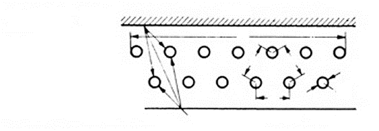
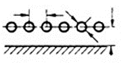
The module provides the standard configurations tabulated in the VDI Heat Atlas: parallel and perpendicular rectangles, coaxial circular disks, cylinders, tube rows (tube banks in front of a wall) and further arrangements. The inputs are the respective geometric quantities such as lengths, widths, radii, spacings and angles; the result is the dimensionless view factor.
Standard and calculation basis: VDI-Wärmeatlas, 12. Auflage 2019
Calculation workflow
- Select the configuration: First, the geometric arrangement that comes closest to the real situation is selected: e.g. parallel rectangles, rectangles sharing a common edge at an angle, coaxial circular disks, concentric cylinders, or a tube row in front of a radiating wall.
- Enter the geometry data: Depending on the configuration, length, width, radius, spacing and, where applicable, the angle between the surfaces are entered. From these quantities the method forms the dimensionless ratios (e.g. radius to spacing or side length to spacing) on which the formulas of the VDI Heat Atlas are based.
- Calculate the view factor: The view factor F12 is evaluated using the closed-form relation for the selected configuration. Analytical solutions of the double surface integral exist for many standard cases; the module implements these relations directly.
- Reverse direction via reciprocity: The reciprocity relation A1·F12 = A2·F21 yields the view factor for the reverse direction. In addition, the summation rule applies: all view factors of a surface in an enclosure add up to 1, which serves as a plausibility check.
- Further use in the radiation balance: The calculated view factor then enters the calculation of the net radiative heat flow together with the emissivities and temperatures of the surfaces, for example in the two-surface model or in a radiation network calculation.
Input quantities
| Quantity | Symbol | Unit |
|---|---|---|
| f_12 | φ12 = | – |
| Angle | α' | ° |
| Angle | α'' φ12 = | ° |
| Angle | α'' φ12 = | – |
| Angle | α φ12 = | ° |
| Angle | α φ12 = | – |
| Angle | α | ° |
| Angle | β φ12 = | ° |
| Angle | β φ12 = | – |
| Spacing | a | m |
| Spacing | b B = b/a = | m |
| Radius | r R = r/a = φ12 = | m |
| Spacing | b B = b/a = | - |
| Radius | r R = r/a = φ12 = | - |
| Radius | r R = r/a = φ12 = | – |
| Spacing | a | m |
| Spacing | b B = b/a = | m |
| Radius | r R = r/a = φ12 = | m |
| Spacing | b B = b/a = | - |
| Radius | r R = r/a = φ12 = | - |
| Radius | r R = r/a = φ12 = | – |
| Spacing | a | m |
| Length | b B = b/a = | m |
| Width | c C = c/a = φ12 = | m |
Calculation options
Bauform
view factor for radiative transfer from a finite surface to an element of area (ΔA1 to A2) · view factor for radiative transfer from finite surfaces (Radiation from A1 to A2) · Radiation from tube banks
Worked example
Two equally sized, coaxial, parallel circular disks (e.g. the bottom and top head of a cylindrical vessel, ignoring the shell) with a radius of 0.5 m face each other at a distance of 1.0 m. Find the view factor F12 from disk 1 to disk 2 — a classic worked example of a radiation view factor calculation.
Given values
| Radius of disk 1, r1 | 0.5 m |
| Radius of disk 2, r2 | 0.5 m |
| Distance h | 1.0 m |
Solution
Form the dimensionless radii
R1 = r1/h = 0.5/1.0 = 0.5
R2 = r2/h = 0.5/1.0 = 0.5
Calculate the auxiliary quantity S
S = 1 + (1 + R22)/R12 = 1 + (1 + 0.25)/0.25 = 6.0
Evaluate the view factor
F12 = ½ · [S − √(S2 − 4·(r2/r1)2)] = ½ · [6 − √(36 − 4)] = ½ · (6 − 5.657) = 0.172
Only about 17 % of the energy radiated by disk 1 therefore strikes disk 2 directly; the rest escapes sideways to the surroundings. Because the areas are equal, F21 = F12.
Result
| View factor F12 | 0.172 |
| View factor F21 (reciprocity, A1 = A2) | 0.172 |
All values are illustrative. The applicable standard and project-specific boundary conditions remain authoritative.
Frequently asked questions
Why does the view factor not depend on temperature?
The view factor is defined as the fraction of diffusely radiated energy that strikes another surface directly. It therefore describes exclusively the geometry of the arrangement. Temperatures and emissivities only enter the radiation balance in the next step — the view factor itself remains constant for a given geometry.
What assumption underlies the formulas?
The tabulated relations assume diffusely emitting and reflecting (Lambertian) surfaces with radiance that is constant over the surface. For strongly specular (mirror-like) surfaces, such as bright metal, the real exchange conditions can deviate; extended models with specular components are then required.
How do I check calculated view factors for plausibility?
Two checks are standard: reciprocity A1·F12 = A2·F21 and the summation rule, according to which all view factors of a surface in a closed enclosure add up to 1. In addition, every view factor must lie between 0 and 1; convex surfaces have no self-view factor (F11 = 0), whereas concave surfaces do.
What do I do with geometries not covered by the standard cases?
Many practical cases can be assembled from the standard configurations by surface decomposition (view-factor algebra): view factors are additive over sub-surfaces. Only if that fails as well are numerical methods such as Monte Carlo ray tracing or contour integration necessary.