Engineering task and calculation objective
The RBSA module performs a flow-induced vibration analysis for tube bundles in shell-and-tube heat exchangers — both for units with two fixed tubesheets and for U-tube designs. It is based on Section 6 of the TEMA standards (9th edition, 2007) and Chapter O2 of the VDI Heat Atlas. The three governing excitation mechanisms of shell-side crossflow are investigated: fluid-elastic instability, vortex shedding and turbulence excitation.
Flow-induced tube vibration is among the most frequent causes of damage in shell-and-tube equipment: it leads to wear at the baffle holes, fatigue cracking at the tube-to-tubesheet expansion, and in extreme cases to tube severance within a few operating hours. A vibration analysis therefore belongs in every design with high shell-side velocity — such as gas coolers, evaporators, or after uprating existing units. TEMA expressly points out that its warranty does not cover vibration damage because of the complexity of the phenomenon; this makes an up-front calculated verification all the more important.
The module determines the natural frequencies of the tubes as a function of end conditions and unsupported span lengths, compares them with the excitation frequencies, and evaluates the critical velocity for fluid-elastic instability.
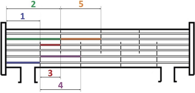
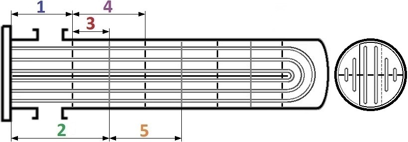
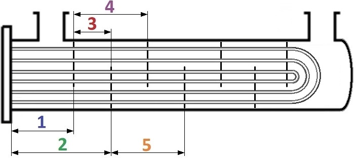
Standard and calculation basis: TEMA, 9. Auflage 2007, Abschnitt 6 & VDI-Wärmeatlas, 12. Auflage 2019, O2
Calculation workflow
- Capture tube and bundle geometry: The inputs are tube dimensions, material properties, tube pitch and layout angle, the span lengths between baffles (including inlet and outlet spans and the U-bend region), and the support conditions at the tubesheet and baffles.
- Calculate tube natural frequencies: For the governing spans, the lowest flexural natural frequency of the tube is calculated as a multi-span beam; the effective mass (tube, internal fluid, added mass of the external fluid) and, for U-tubes, the bend geometry are taken into account. In addition, the damping is estimated.
- Determine flow velocities in the bundle: From the mass flow rate, density and bundle geometry, the crossflow velocities in the critical zones are determined — the inlet region below the nozzle, the baffle window zone and the bypass gaps.
- Check fluid-elastic instability: Using the stability map (Connors approach), the critical velocity is calculated above which the tubes excite each other into growing oscillation. The actual effective velocity must stay below it with sufficient margin — this mechanism is the most dangerous because amplitudes grow abruptly above the threshold.
- Evaluate vortex and turbulence excitation: The vortex shedding frequency is determined via the Strouhal number from velocity and tube diameter and checked for proximity to resonance with the natural frequency; for broadband turbulence excitation, the expected vibration amplitudes are estimated and compared with the allowable values (clearance, fatigue).
- Derive remedial measures: In case of exceedances, design countermeasures are evaluated: closer baffle spacing, intermediate supports or U-bend support grids, modified tube pitch, impingement protection or a modified nozzle arrangement — and the analysis is repeated with the new geometry.
Input quantities
| Quantity | Symbol | Unit |
|---|---|---|
| Outside diameter of tube | do | m |
| Inside diameter of tube | di | m |
| Wall thickness of tubes | et | m |
| Et | Et | N/mm² |
| \u03c1t | \u03c1t | kg/m³ |
| Distance from tubesheet to1st baffle | l | m |
| Medium | außen | – |
| \u03c1o | \u03c1o | kg/m³ |
| Kinematic visocsity | ν | m²/s |
| Transverse pitch (pt) | s1 | m |
| Longitudinal pitch (pl) | s2 | m |
| Tube pitch (P) | t | m |
| Tube pitch according to TEMA | Teilungswinkel | – |
| Tubes in windows? | Fenster? | – |
| wn | wn | m/s |
| Number of shell-side passes | nD | – |
| ltot,45 | ltot,45 | m |
| po | po | Pa |
| \u03c1i | \u03c1i | kg/m³ |
| Total volumetric flow rate | V | m³/s |
| Tube pitch ratio (P/do) | τ | – |
| ltot,2 | ltot,2 | m |
| Baffle spacing | l | m |
| Number of baffles per shell-side pass | NB,tot | – |
Calculated results
| Quantity | Symbol | Unit |
|---|---|---|
| V12 | V12 | ft/s |
| V345 | V345 | ft/s |
| VU | VU | ft/s |
| fvs,2 | fvs,2 | 1/s |
| fvs,345 | fvs,345 | 1/s |
| fvs,U | fvs,U | 1/s |
| yvs,1 | yvs,1 | in |
| yvs/do,1 | yvs/do,1 | - |
| f_vs | f_vs | – |
| y_vs/d_o<=2% | y_vs/d_o<=2% | – |
| yvs,2 | yvs,2 | in |
| yvs/do,2 | yvs/do,2 | - |
| f_vs | f_vs | – |
| y_vs/d_o<=2% | y_vs/d_o<=2% | – |
| yvs,3 | yvs,3 | in |
| yvs/do,3 | yvs/do,3 | - |
| f_vs | f_vs | – |
| y_vs/d_o<=2% | y_vs/d_o<=2% | – |
| yvs,4 | yvs,4 | in |
| yvs/do,4 | yvs/do,4 | - |
| f_vs | f_vs | – |
| y_vs/d_o<=2% | y_vs/d_o<=2% | – |
| yvs,5 | yvs,5 | in |
| yvs/do,5 | yvs/do,5 | - |
Calculation options
Medium
liquid · gaseous · two phase
Tube pitch according to TEMA
30 · 45 · 60 · 90
Tubes in windows?
No-Tube-in-Window (NTIW) · With tubes in windows
Seal strips
No · Yes
Type of bundle
Fixed tubesheets · U-Bend · Floating head · Outside packed floating head
Inlet
Inlet at tubesheet · Inlet at U-bend
Expansion joint with total expansion compensation implemented?
No · Yes
Frequently asked questions
Why is fluid-elastic instability more critical than vortex or turbulence excitation?
Vortex and turbulence excitation produce forced vibrations with limited, predictable amplitude. Fluid-elastic instability, by contrast, is a self-excited mechanism: above the critical velocity, the coupling between tube motion and fluid forces leads to negative damping, and amplitudes grow abruptly until neighbouring tubes impact each other. Damage then occurs not after years, but after hours to weeks. This is why a substantial safety margin to the critical velocity is required here.
What role does the Strouhal number play in the analysis?
The Strouhal number links the vortex shedding frequency to the approach velocity and the tube diameter (f = Sr·v/d). Within the bundle it depends on the pitch ratio and layout angle and is determined from charts or correlations (TEMA, VDI Heat Atlas). If the shedding frequency lies close to a tube natural frequency (lock-in range), resonance threatens — and with gases, acoustic resonances of the shell-side space can be excited in addition, whereas with liquids the acoustic aspect is not critical.
Which locations in the bundle are most at risk, based on experience?
The longest unsupported spans with the highest crossflow velocity: the inlet region directly below the nozzle (high local velocity, often with additional flow around the impingement plate), the window tubes, which are supported only at every second baffle, and in U-tube units the U-bend with its large free length and low natural frequency. This is exactly where the usual remedies (support grids, impingement protection, pitch modification) are applied.
Does a TEMA-compliant design replace the vibration analysis?
No. The TEMA maximum unsupported spans only prevent static sagging and gross design errors; they do not guarantee freedom from vibration. TEMA explicitly excludes vibration damage from its warranty. For high shell-side velocities, gases at high pressure or two-phase flow, the analysis per Section 6 or VDI Heat Atlas O2 must always be carried out separately.