Engineering task and calculation objective
Module EN13.04 calculates tubesheets of U-tube heat exchangers to DIN EN 13445-3, clause 13.4. In a U-tube exchanger, the tube bundle is fixed to a single tubesheet only; the thermal expansion of the tubes is accommodated without restraint by the U-bends. The tubesheet is therefore not loaded by axial restraint forces, but it is loaded by the pressure difference between the tube side and the shell side and by the edge moments from the connected flanges.
To calculate a U-tube tubesheet to EN 13445-3 means verifying the bending capacity of the plate, weakened by the perforated tube field, for all governing pressure combinations: shell-side and tube-side design pressures acting individually and together, plus the test conditions of both sides. The support conditions at the plate edge — integrally attached, gasketed, or a combination with a flange — largely determine the calculation coefficients.
The module covers the configurations of clause 13.4 including the subsequent conditions and is used for the design and re-rating of U-tube heat exchangers in process and power plants.
Standard and calculation basis: DIN EN 13445-3/13.4: 2021-12
Calculation workflow
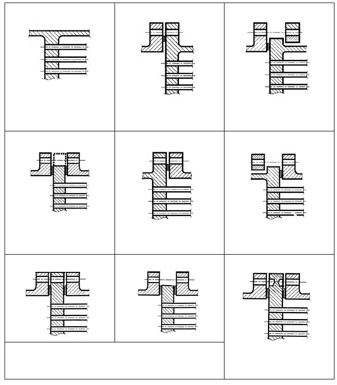
- Define the configuration: First the attachment configuration of the tubesheet is selected: integrally welded to shell and/or channel, gasketed, or with a flanged extension — the configuration determines the boundary conditions and coefficients of the calculation.
- Define pressures and load cases: The shell-side and tube-side design pressures and the corresponding test pressures are specified. The standard requires verification of all pressure combinations, since depending on the sign of the pressure difference different conditions become governing.
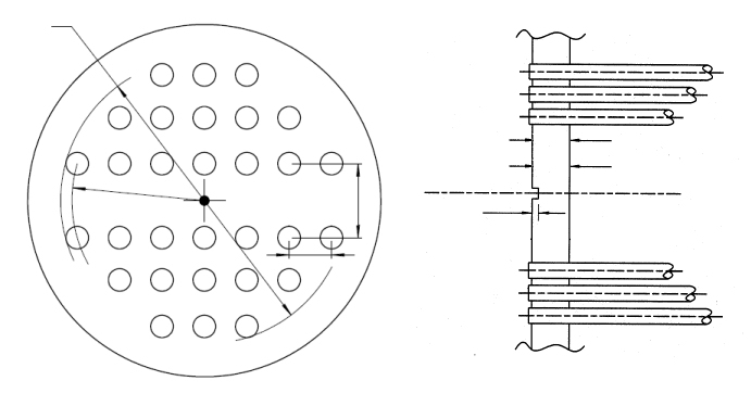
- Capture the tube-field weakening: From the tube pitch, the tube hole diameter and, where applicable, welded-in or expanded tubes, the ligament efficiency of the perforated field is determined, which reduces the bending capacity of the plate.
- Perform the stress verifications: For each pressure combination, the bending stresses in the tubesheet and the stresses in the junctions to shell and channel are calculated and compared with the allowable values; for gasketed configurations the flange moments enter the calculation.
- Assess the result: The least favourable combination of operating and test conditions governs; the module reports the required tubesheet thickness or the utilization of the selected thickness.
Input quantities
| Quantity | Symbol | Unit |
|---|---|---|
| Configuration of the tubesheet | Rohrboden | – |
| Shell-side design pressure (inside) | PBs | MPa(p) |
| Tube-side design pressure (inside) | PBt | MPa(p) |
| Shell-side test pressure (inside) | PPs | MPa(p) |
| Tube-side test pressure (inside) | PPt | MPa(p) |
| Load case (1) | Ps=0 Pt OC1 | – |
| Load case (2) | Ps Pt=0 OC2 | – |
| Load case (3) | Ps Pt OC3 | – |
| Load case (1) | Ps=0 Pt TC1 | – |
| Load case (2) | Ps Pt=0 TC2 | – |
| Load case (3) | Ps Pt TC3 | – |
| Start-up and Shut-down | SSC | – |
| Exceptional operating condition | EXC | – |
| Material | Boden | – |
| Rohre | Rohre | – |
| Schale | Schale | – |
| Vorkammer | Vorkammer | – |
| Design temperature | T | °C |
| Nominal wall thickness *) | eN | mm |
| Outside diameter | A | mm |
| Poisson's ratio | \u03bd | - |
| Tolerance | \u03b4 | mm |
| Corrosion allowance | c | mm |
| Nominal design strength (Operation) | KOp | N/mm² |
Calculated results
| Quantity | Symbol | Unit |
|---|---|---|
| OLC1 | OLC1 | – |
| OLC2 | OLC2 | – |
| OLC3 | OLC3 | – |
| TLC1 | TLC1 | – |
| TLC2 | TLC2 | – |
| TLC3 | TLC3 | – |
| SSC | SSC | – |
| EXC | EXC | – |
| OLC1 | OLC1 | – |
| OLC2 | OLC2 | – |
| OLC3 | OLC3 | – |
| TLC1 | TLC1 | – |
| TLC2 | TLC2 | – |
| TLC3 | TLC3 | – |
| SSC | SSC | – |
| EXC | EXC | – |
| OLC1 | OLC1 | – |
| OLC2 | OLC2 | – |
| OLC3 | OLC3 | – |
| TLC1 | TLC1 | – |
| TLC2 | TLC2 | – |
| TLC3 | TLC3 | – |
| SSC | SSC | – |
| EXC | EXC | – |
Calculation options
Configuration of the tubesheet
a - tubesheet integral with shell and channel · b - tubesheet extended as flange / integral with shell / gasketed with channel / narrow-face gasket · b' - tubesheet extended as flange / integral with shell / gasketed with channel / full-face gasket · c - tubesheet not extended as flange / integral with shell / gasketed with channel · d1 - tubesheet not extended as flange / gasketed with shell and channel / narrow-face gasket · d1' - tubesheet not extended as flange / gasketed with shell and channel / full-face gasket · d2 - tubesheet extended as flange / gasketed with shell and channel / narrow-face gasket · d2' - tubesheet extended as flange / gasketed with shell and channel / full-face gasket · e - tubesheet extended as flange / gasketed with shell / integral with channel / narrow-face gasket · e' - tubesheet extended as flange / gasketed with shell / integral with channel / full-face gasket · f - tubesheet not extended as flange / gasketed with shell / integral with channel
Tube arrangement
triangular · rectangular
Tube - Tubesheet connection
welded · rolled-in without groove acc. fig. 13.7.3-3 · rolled-in with one groove · rolled-in with two grooves · welded acc. fig. 13.12.3-1 · welded acc. fig. 13.12.4-1 to 13.12.7-1
Determination of bolt load
calculate · enter
Use option 3?
No · Yes
Frequently asked questions
Why is the U-tube tubesheet simpler to calculate than a fixed tubesheet?
Because the U-tube bundle can expand axially without restraint, no interaction forces arise between tubes and shell. The tubesheet carries only the pressure difference and the edge moments — the elaborate coupled analysis of tube-field stiffness, shell expansion and temperature difference required for the fixed-tubesheet exchanger (clause 13.5) is not needed.
Why must both pressures also be verified acting individually?
Operating situations such as start-up, shutdown or a one-sided pressure test mean that at times only one side is under pressure. The bending load on the tubesheet depends on the pressure difference and can be larger in these situations than in normal operation with pressure on both sides — the standard therefore requires all combinations including the test conditions.
What role does the support condition at the plate edge play?
Whether the tubesheet is integrally welded to shell and channel or is gasketed changes the edge moments and thus the governing bending stress considerably. For gasketed configurations, the bolt and gasket forces of the flange enter in addition; the configuration must match the real construction exactly, otherwise the verification is not reliable.
Does the calculation also consider the tubes as supports?
In a U-tube exchanger the tubes do not support the plate like an elastic foundation, because they are fixed to only one tubesheet. The perforated field acts as a weakening via the ligament efficiency; the tube-to-tubesheet joint must be verified separately against the pull-out and compression forces.