Engineering task and calculation objective
This module serves for the design and simulation of evaporators for pure substances in shell-and-tube or double-pipe construction according to the calculation sheets of the VDI Heat Atlas (VDI-Wärmeatlas). It covers forced-flow evaporators without liquid preheating and without vapor superheating — the supplied heat is thus used entirely to vaporize the medium entering at its boiling point. The heating medium can flow single-phase or itself be condensing.
Calculating evaporators is required in many places in process engineering: evaporators of chillers and heat pumps, forced-circulation evaporators of evaporation plants, LNG and liquefied-gas vaporizers, and reboilers with pumped circulation. The difficulty lies in flow boiling: along the tube, the vapor quality changes continuously, and with it the flow pattern, the heat transfer coefficient and the pressure drop — a hand calculation with a constant U-value falls short here. The module therefore subdivides the apparatus computationally and evaluates the boiling correlations of the VDI Heat Atlas as functions of the local state.
Standard and calculation basis: VDI Wärmeatlas
Calculation workflow
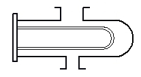
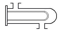
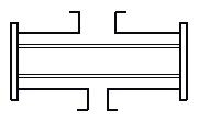
- Define the task and construction type: The design type is selected (tube bundle with fixed tubesheet, floating head or U-tube, or double pipe), along with the installation orientation, the tube layout with pitch and number of passes, and the assignment of the evaporating medium and the heating medium to the tube and shell sides.
- Determine property data and operating point: For the pure substance, the saturation pressure or temperature, the heat of evaporation and the properties of boiling liquid and saturated vapor are determined; for the heating medium, the inlet state, mass flow and properties. The required heat duty follows from the demanded vapor rate.
- Calculate flow boiling heat transfer: Along the flow path, the local heat transfer coefficient is determined from the contributions of convective boiling and nucleate boiling per the VDI Heat Atlas — depending on mass flux, vapor quality, heat flux and pressure. At the same time, the critical heat flux is monitored to rule out film boiling or dryout of the wall.
- Form the heating-side heat transfer and the overall heat transfer: For the heating medium, the heat transfer is calculated for single-phase flow or condensation; together with wall conduction and fouling resistances, this yields the local overall heat transfer coefficient.
- Balance the area and check the pressure drop: Through section-wise integration over the vapor quality, the required area, the outlet states and the performance margin of the selected apparatus are determined. The two-phase pressure drop is calculated as well, since it feeds back directly on the driving temperature difference via the saturation temperature.
Input quantities
| Quantity | Symbol | Unit |
|---|---|---|
| Mass flow Mass flow | mi ma | – |
| Mass flow Mass flow | mi ma | – |
| Volume flow Volume flow | Vi Va | – |
| Volume flow Volume flow | Vi Va | – |
| Density Density ρa | ρi | – |
| Density Density ρa | ρi | – |
| Specific heat capacity Specific heat capacity | cpi cpa | – |
| Specific heat capacity Specific heat capacity | cpi cpa | – |
| Inlet temperature Inlet temperature | ϑei ϑea | – |
| Outlet temperature Outlet temperature | ϑai ϑaa | – |
| Inlet temperature Inlet temperature | ϑei ϑea | – |
| Outlet temperature Outlet temperature | ϑai ϑaa | – |
| Heat duty Heat duty | Qi Qa | – |
| Heat duty Heat duty | Qi Qa | – |
| Heat loss | Qva | – |
| Thermal conductivity | λt | – |
| Heat transfer area | A Aa | – |
| Outside diameter Wall thickness | da si | – |
| Inside diameter | di | – |
| Boiling temperature Mean temperature | ϑmi ϑma | – |
| Boiling temperature Mean temperature | ϑmi ϑma | – |
| Mean tube wall temperature Mean tube wall temperature | ϑwi ϑwa | – |
| Mean tube wall temperature Mean tube wall temperature | ϑwi ϑwa | – |
| Heat of evaporation Heat of evaporation | ΔhV ΔhV | – |
Calculated results
| Quantity | Symbol | Unit |
|---|---|---|
| Heat transfer coefficient (tube-side) | αi | – |
| Heat transfer coefficient | αο | – |
| Total fouling resistance | f | – |
| Logarithmic mean temperature diff. LMTD | Δϑ | – |
| Overall heat transfer coefficient | k | – |
| Number of tubes | N | – |
| FN Factor (Correction factor for LMTD) | FN | – |
| Mean heat flux | q | – |
| Critical heat flux | qcr | – |
| Number of tubes U-tubes | N | – |
Calculation options
No tubes in window
No · Yes
Frequently asked questions
Why does the module apply only to pure substances without preheating and superheating?
For a pure substance, the boiling temperature at a given pressure is constant — the driving temperature difference can be formed cleanly. For mixtures, the boiling temperature shifts with composition and the heat transfer is reduced by mass transfer resistances. Preheating and superheating zones would moreover involve entirely different heat transfer mechanisms (single-phase convection) and their own area fractions; they are treated in separate apparatuses or modules. The restriction keeps the calculation within the validated range of the boiling correlations.
What does forced flow mean as opposed to natural circulation?
In a forced-flow evaporator, a pump sets the mass flux, making it a known input to the boiling correlations. In natural circulation, the density difference between downcomer and riser alone drives the circulation — mass flow, vapor quality and pressure drop must then be brought into equilibrium iteratively. Forced flow allows higher and more stable mass fluxes and thus protects the heating surface better against dryout.
What is the critical heat flux and why must I stay below it?
Above the critical heat flux, the liquid film on the heating surface breaks down or an insulating vapor film forms (film boiling, dryout). The heat transfer coefficient then collapses by a large factor; with temperature-controlled heating, the duty drops drastically, while with power-controlled heating, the wall temperature jumps and can damage the material. The design must therefore demonstrate a sufficient margin to the critical heat flux everywhere in the apparatus.
What role does the pressure drop on the boiling side play?
A greater one than in a single-phase apparatus: the two-phase pressure drop lowers the local saturation pressure and thus the boiling temperature along the flow path. At small driving temperature differences — typical in refrigeration plants — this can consume a substantial part of the temperature gradient. Pressure drop and heat transfer calculations must therefore be carried out in coupled form, as this module does section by section.