Engineering task and calculation objective
In heat exchangers with two fixed, rigidly designed tubesheets, the tube bundle and the shell are rigidly coupled: if tubes and shell expand by different amounts, they restrain each other and axial forces arise that cannot be inferred from the tube-side or shell-side pressure alone. These restraint forces can compress or stretch the tubes and impose additional load on the shell — a classic damage mechanism in fixed-tubesheet exchangers without an expansion joint.
The B51A module performs the verification of the axial forces to AD 2000-Merkblatt B5, clause 6.7.1.7, of the German AD 2000 pressure vessel code. For rigid, firmly anchored tubesheets it determines the stresses in the shell and in the tubes from pressure loading and restrained thermal expansion. The basis is a compatibility approach: the unloaded lengths of shell and bundle at bolt-up, shell and tube temperatures are compared with the mutually restrained lengths; from the enforced common deformation, the forces follow via the moduli of elasticity and the load-bearing cross-sections.
In practice, this verification decides whether a fixed-tubesheet heat exchanger may be built without an expansion joint, or whether expansion compensation (an expansion joint, U-tube or floating-head design) is required. The module thus complements the tubesheet design to B51.
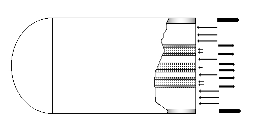
Standard and calculation basis: AD 2000 B5/6.7.1.7
Calculation workflow
- Define the operating condition: The inputs are the pressure in the tubes, the pressure around the tubes, the operating temperatures of shell and tubes, the design temperature of the shell, and the assembly temperature at which the connection was made stress-free.
- Enter material and cross-section values: For the shell and the tubes, the nominal design stress, safety factor, modulus of elasticity and coefficient of thermal expansion at the respective temperatures are required. The module determines the load-bearing cross-sections of shell and tube bundle as well as the pressure-loaded areas in and around the tubes.
- Calculate the lengths in the unrestrained state: Starting from the length at the assembly temperature t0, the unloaded lengths of shell and tubes at the shell temperature tM and the tube temperature tR are determined via the coefficients of expansion — as if both components could expand freely.
- Enforce compatibility and iterate the forces: Since shell and tubes are forcibly coupled through the rigid tubesheets, their lengths must coincide in the restrained state. The module iterates the common length (automatically, if desired) and from it calculates the axial restraint forces, superimposed with the forces from the pressure-loaded areas of both chambers.
- Evaluate the stresses: From the resulting axial forces and the load-bearing cross-sections follow the stresses in the shell and in the tubes; they are compared with the allowable values K/S in the operating condition. In addition, the module reports the required shell wall thickness and comments on the result.
Input quantities
| Quantity | Symbol | Unit |
|---|---|---|
| Outside shell diameter | Da | mm |
| Inside shell diameter | Di | mm |
| Outside tube diameter | da | mm |
| Inside tube diameter | di | mm |
| Number of tubes | n | – |
| Pressure in the tubes | pi | bar |
| Pressure around the tubes | pa | bar |
| Shell temperature operating conditions | tM | °C |
| Design temperature tube side | tR | °C |
| Bolt up temperature | t0 | °C |
| Coefficient of expansion of the shell | αM | 1E-6/K |
| Coefficient of expansion of the tubes | αR | 1E-6/K |
| Modulus of elasticity of shell | EM | N/mm² |
| Modulus of elasticity of tubes | ER | N/mm² |
| Length at t0 (unloaded) | L0 | mm |
| Length at tM (unloaded) | LMt | mm |
| Length at tR (unloaded) | LRt | mm |
| Length at tM (mutually restrained springs) | LM | mm |
| Length at tR (mutually restrained springs) | LR | mm |
| Length without bending of the plate | L | mm |
| Bearing cross section of the shell | AM | mm² |
| Bearing cross section of the tubes | AR | mm² |
| Pressure-loaded area in the tubes | Ai | mm² |
| Pressure-loaded area around tubes | Aa | mm² |
Calculated results
| Quantity | Symbol | Unit |
|---|---|---|
| Stress in the shell | σM | N/mm² |
| Stress in the tubes | σR | N/mm² |
| Strain in the shell | eM | – |
| Strain in the tubes | eR | – |
| Cross-sectional force of the shell | FM | N |
| Cross-sectional force of the tubes | FR | N |
| Pressure force in the tubes | Fi | N |
| Pressure force around the tubes | Fa | N |
| Remark | Bemerkung | – |
| Net wall thicknes shell side | s | mm |
| Stress in the shell | σM | N/mm² |
| Required wall thickness | se | mm |
| Stress in the welding seams | σA | N/mm² |
| Cross-sectional force of one tube | FR,1 | N |
Calculation options
Calculation Options
Use all tubes · Use only boundary tubes
Frequently asked questions
When is the axial force verification to B5 clause 6.7.1.7 required?
Whenever both tubesheets are firmly connected to the shell and are so rigid that they cannot accommodate the differential expansion between bundle and shell through plate bending. With flexible (thin) tubesheets, U-tube or floating-head designs, and shells with an expansion joint, the rigid coupling is absent and this form of the verification does not apply.
Which load case typically governs?
Not necessarily the design condition: the critical cases are often start-up and shutdown transients in which one side is already hot while the other is still cold, so that the temperature difference between tubes and shell reaches its maximum. The test condition with one-sided pressurization should also be considered. It is advisable to run several temperature-pressure combinations.
Why does the assembly temperature enter the calculation?
The assembly temperature defines the stress-free reference state: at this temperature, tubes and shell were welded together free of forces. All restraint forces arise from the deviation of the operating temperatures from this reference state. An incorrectly assumed assembly temperature shifts all the thermal stresses.
What can be done if the verification fails?
Options include an expansion joint in the shell (then verified to B6 or per the manufacturer's data), switching to a U-tube or floating-head design, a different material pairing with more similar coefficients of expansion, or operational measures such as controlled start-up and shutdown ramps to limit the temperature difference.