Engineering task and calculation objective
The VSA module sizes vertical gravity separators for gas-liquid mixtures. Calculated are the limiting droplet settling velocity with and without a demister (wire mesh pad), the required vessel diameter, the nozzle velocities at the inlet and at the gas and liquid outlets, the high and low liquid levels for the required residence times, and the vortex breaker design at the liquid outlet. The calculation is based on established methods from the technical literature, including the VDI Heat Atlas for the flow pattern in the feed line and Bürkholz's standard work on droplet separation.
Gas-liquid separators are found in almost every process plant: as suction drums upstream of compressors, as flash drums, at column overheads, or in natural gas processing. The sizing of a gravity separator decides whether droplets are separated reliably or leave as liquid carry-over that endangers downstream machines and equipment — an undersized diameter is one of the most frequent causes of compressor damage.
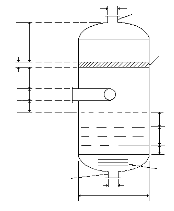
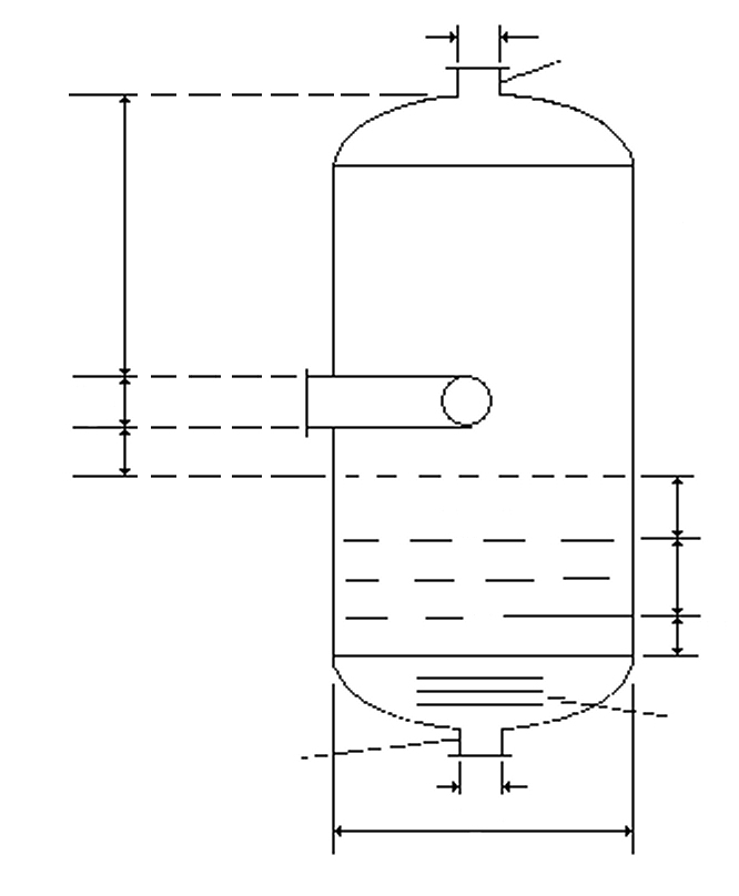
To this end, the module checks the governing velocity criteria: the allowable gas velocity in the separation space (limiting droplet model or mesh pad loading), the maximum inlet velocity at the inlet nozzle and distributor, the outlet velocities, and the required distance between the inlet and the highest liquid level (HLL).
Standard and calculation basis: Harlemann "Selective Withdrawal from a vertically Stratified Fluid", Intern. Assoc. Hydro. Research Patterson "Experimental Investigation of Critical Submergence for Vortexing in a vertical Cylindrical Tank", University of Southern California VDI-Wärmeatlas / Strömungsformen für Zweiphasen-Strömung R. Marr und F. Moser "Verfahrenstechnik 9" (1975) Nr. 8, S. 379/382 A.Bürkholz, Droplet Separation, VCH. 1989
Calculation workflow
- Determine operating data and flow pattern: From the volume flows and densities of gas and liquid, the flow pattern in the feed line is first assessed using the two-phase flow maps (VDI Heat Atlas) — it determines how strongly dispersed the liquid arrives at the inlet and which inlet device is suitable.
- Allowable gas velocity in the separation space: Without a demister, the allowable gas velocity follows from the settling velocity of the limiting droplet that can just still settle against the upward gas flow; with a demister, from the allowable mesh pad loading. From this follows the required vessel diameter for the specified gas flow.
- Size the nozzles: The velocities at the inlet pipe, the gas outlet, and the liquid outlet are calculated and compared with the allowable values (e.g. the momentum flux criterion at the inlet, to avoid droplet shattering and mesh pad damage). The required distance between the inlet nozzle and the highest liquid level (HLL) ensures that the gas flow does not tear open the liquid surface.
- Set liquid levels and residence times: From the required residence and response times (e.g. for control and alarming), the high and low liquid levels (HLL/LLL) and thus the necessary liquid volume between the levels are determined.
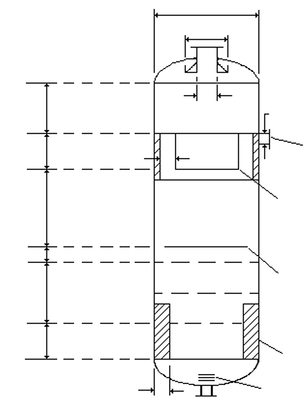
- Check vortex breaker and entrainment: At the liquid outlet, the critical submergence against vortex formation is checked using the methods of Harlemann and Patterson, and a vortex breaker is sized so that no gas is drawn into the liquid line. In addition, liquid entrainment from surfaces is assessed.
Input quantities
| Quantity | Symbol | Unit |
|---|---|---|
| Separator with CWMS | = 1 CWMS = Crinkled Wire Mesh Screen | – |
| Gas flow rate | Vg | m³/h |
| Liquid feed rate | Vl | m³/h |
| Density liquid | ρl | kg/m³ |
| Density gas | ρg | kg/m³ |
| Surface tension | σ | mN/m |
| Dynamic viscosity gas | ηg | mPa·s |
| Dynamic viscosity liquid | ηl | mPa·s |
| Critical velocity in separator | voG | m/s |
| Nozzle gas inlet | dge | mm |
| Nozzle gas outlet | dga | mm |
| Distance CWMS-outlet | h7 | mm |
| Slot width | s | mm |
| Hole diameter | dh | mm |
| Vessel diameter | D | mm |
| Distance LLL-outlet | h1 | mm |
| Diameter of CWMS | DG | mm |
| Support ring width | W | mm |
| Maximum critical velocity | vmax | % |
| Velocity in the separator | vAb | m/s |
| Critical velocity in separator | vmG | m/s |
| Holdup time (ELL-HLL) | t3 | min |
| Height (ELL-HLL) | h3 | mm |
| Holdup time (HLL-LLL) | t2 | min |
Calculated results
| Quantity | Symbol | Unit |
|---|---|---|
| Maximum velocity inlet nozzle | ve | m/s |
| Required distance inlet-HLL | x | mm |
| Velocity inlet nozzle | ve,in | m/s |
| Velocity liquid outlet nozzle | vl | m/s |
| Velocity gas outlet nozzle | vg | m/s |
Frequently asked questions
When is a gravity separator without a demister sufficient, and when is a wire mesh pad needed?
Pure gravity separation captures only relatively large droplets — economical vessel sizes achieve limiting droplets of about 100 to 300 µm. A wire mesh demister also separates droplets down to a few micrometers and at the same time permits higher gas velocities, i.e. smaller diameters. You can do without a demister if coarse carry-over is acceptable or if the mesh pad is ruled out due to fouling, encrustation, or polymerization.
What is the limiting droplet and how does it determine the vessel diameter?
The limiting droplet is the smallest droplet that is still to be separated. Its terminal settling velocity in the gas — from the force balance of weight, buoyancy, and drag — is the maximum allowable upward gas velocity in the separation space. The vessel cross-section must be large enough that the gas volume flow does not exceed this velocity; the diameter follows directly from it.
Why is the inlet velocity limited?
An excessive momentum flux (ρ·w²) at the inlet shatters the liquid into fine secondary droplets that gravity separation can no longer capture, and can mechanically damage mesh pads. Common design rules therefore limit ρ·w² at the inlet nozzle and provide inlet devices (impact plate, vane distributor, cyclonic inlet) that dissipate the momentum and take over the primary separation.
What is the vortex breaker at the liquid outlet for?
If the submergence above the outlet nozzle falls below the critical height, an air-entraining vortex forms through which gas enters the liquid line — with cavitation and loss of flow at downstream pumps as the consequence. The vortex breaker (cross plate or perforated plate above the nozzle) suppresses the rotation; the module checks the critical submergence using the experimental methods of Patterson and Harlemann and sizes the vortex breaker.