Engineering task and calculation objective
Support skirts are the classic installation solution for vertical pressure vessels and columns: a cylindrical or conical shell of plate carries the entire weight of the apparatus including internals and contents, and additionally transfers bending moments from wind or seismic loads into the foundation. This module performs the design verification of support skirts to DIN EN 13445-3, clause 16.12 — the code section covering non-pressure-bearing parts and vessel supports of unfired pressure vessels.
The calculation is split into two separate checks: first, the local stresses in the junction region between skirt and vessel wall, where compressive stresses from the internal vessel pressure superimpose on the section forces from the support reaction; second, the verification of the skirt itself against yielding and buckling failure. Both cylindrical and conical skirts are supported, as well as connection via a support ring or skirts welded directly to the vessel wall or to the dished end (Klöpper or Korbbogen type torispherical head).
To calculate a support skirt to EN 13445 you need, besides the skirt geometry, the section forces at the junction — weight force, shear force and bending moment. The module determines the required section forces and evaluates the governing stress combinations for the operating and the test condition.
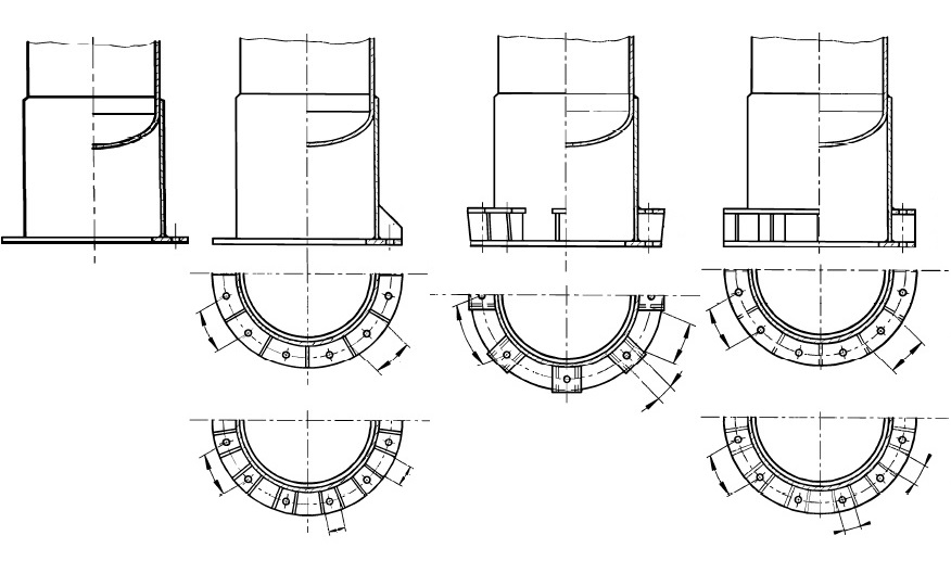
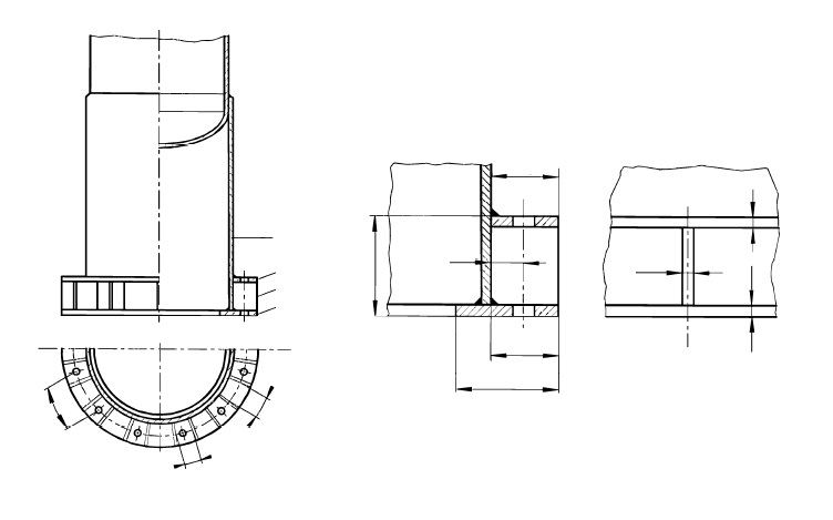
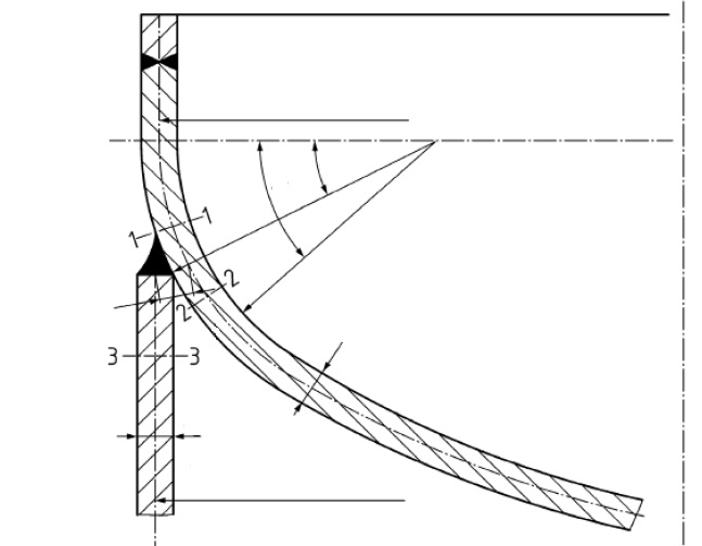
Standard and calculation basis: DIN EN 13445-3/16.12: 2018-12
Calculation workflow
- Enter the geometry of vessel and skirt: First, the outside diameter, inside diameter and nominal wall thickness of the vessel are entered; from these the module derives the mean diameter and the analysis wall thickness. For the skirt, the design type (cylindrical or conical), diameter, wall thickness and the connection variant (support ring or directly welded) are specified.
- Determine loads and section forces: At the skirt-to-vessel junction the governing section forces are compiled: dead weight of the apparatus with internals and contents, test filling where applicable, and the global bending moment from wind or seismic loading. The verifications are carried out separately for the relevant load cases (operation, testing, erection).
- Verify local stresses at the junction: In the connection region, the membrane stresses from the internal or external pressure of the vessel superimpose on the local bending and membrane stresses from the load introduction of the skirt. The module evaluates the stress combinations according to clause 16.12 and compares them with the allowable values of the vessel material.
- Verification of the skirt itself: For the skirt shell, verification is performed against yielding under longitudinal compressive stress and against stability failure (buckling). For conical skirts the inclination enters the stress determination; openings in the skirt reduce the load-bearing cross-section.
- Assessment and documentation: Finally, the module compiles utilization ratios for all verification points. If conditions are violated, the skirt wall thickness, support ring dimensions or reinforcements can be adjusted and the verification repeated immediately.
Input quantities
| Quantity | Symbol | Unit |
|---|---|---|
| Wall thickness ratio | eB/eZ | - |
| Type of head | Bodenart | - |
| Ratio | eB/DB | - |
| Condition for construction type B (0,5 ≤ eB/ez ≤ 2,25) not satisfied! | 0,5 ≤ eB/ez ≤ 2,25 | - |
| Section force in skrt support (p) | FZp | N |
| Global additional axial force in 1-1 (Fig. 16.12-4) | F1 | N |
| Weight of vessel without contents | FG | N |
| Weight of vessel contents | FF | N |
| resulting moment from external loads in section 1-1 (Fig. 16.12-4) | M1 | N·mm |
| Mean diameter of skirt support | DZ | mm |
| Section force in skrt support (q) | FZq | N |
| Membrane stress (p) | \u03c31pm | N/mm² |
| Strength condition | (16.12-5) | - |
| Weight of vessel (without contents) below section 2-2 | ΔFG | N |
| Calculation pressure | P | MPa |
| Mean diameter of vessel | DB | mm |
| Design wall thickness of vessel | eB | mm |
| Membrane stress (q) | \u03c31qm | N/mm² |
| Strength condition | (16.12-6) | - |
| Required wall thickness (p) | e1pm | mm |
| allowable stress Vessel | f | N/mm² |
| Required wall thickness (q) | e1qm | mm |
| Nominal wall thickness of vessel | enB | mm |
| Outside diameter of skirt support | DZa | mm |
Calculation options
Type of head
Kloepper type · Torispherical head (Korbbogen type) · Elliptical head
Design of anchor bolts and base ring?
No · Yes
Thread pitch according to regulation
1 · 2
Type of base ring
Type 1 · Type 2 A · Type 2 B · Type 3 · Type 4 A · Type 4 B
Type
A: Skirt connection by support ring at cylindrical area · B: Skirt connected to knuckle area · C: Slip-on skirt support
Frequently asked questions
How does connection via a support ring differ from a directly welded skirt attachment?
With a directly welded skirt, the support reactions are introduced straight through the weld into the vessel wall or the knuckle of the dished end — local bending stresses arise there that must be verified separately. A support ring distributes the load introduction over a larger area and partially decouples skirt and vessel wall; in return, the ring and its connection must be verified in addition. Which variant is more favourable depends on vessel diameter, wall thickness and moment loading.
Which loads must be considered in the skirt support verification?
Besides the dead weight of the empty apparatus, internals, insulation, operating contents and — frequently governing — the water filling during the pressure test must be applied. Added to these are global bending moments from wind to EN 1991-1-4 or earthquake to EN 1998, plus loads from connected piping where applicable. The combination of maximum moment with minimum or maximum vertical load decides whether the tension or the compression side governs.
Why is the junction region verified separately from the skirt itself?
The failure mechanisms are different: in the junction region, local membrane and bending stresses in the pressure-bearing vessel wall limit the load capacity, whereas in the skirt the limits are yielding under longitudinal compression and elastic-plastic buckling of the thin-walled shell. EN 13445-3 clause 16.12 therefore treats both verifications with their own criteria and allowable stresses.
Are openings in the support skirt permissible?
Yes — manholes, pipe penetrations and ventilation openings are common in support skirts. However, they reduce the load-bearing cross-section and increase the stresses in the remaining section, particularly on the compression side under bending moment. Larger openings must be reinforced (e.g. by frames or welded-on reinforcements) and accounted for in the verification of the section forces.