Engineering task and calculation objective
The S34 module performs the general stability verification for vessels with support brackets to AD 2000-Merkblatt S3/4 of the German AD 2000 pressure vessel code. Support brackets (lugs) are brackets welded to the cylindrical wall by which vertical vessels are set down on steel structures, cross-beams or concrete supports – one of the most common installation methods for medium-sized apparatus in plant engineering. The brackets introduce the weight loads and moments locally into the pressure-loaded vessel wall.
The verification covers both sides of the connection. On one side, the vessel wall, in which the bracket force generates local membrane and bending stresses that must be superposed with the stresses from the design pressure at the bracket plane – this wall calculation can also be used generally for the introduction of additional forces without openings in the vessel wall. On the other side, the bracket itself: the bearing plate, the web plate and, where present, the reinforcing plate are sized, and the required core diameter of the anchor bolts is determined.
Inputs are the load case, the design pressure and temperature at the bracket plane, the total moments and the maximum total weight load, the number of brackets, and the material, nominal design strength, safety factors and allowances. The module to AD 2000 S3/4 is thus part of the standard scope of every vessel calculation with bracket-supported installation.
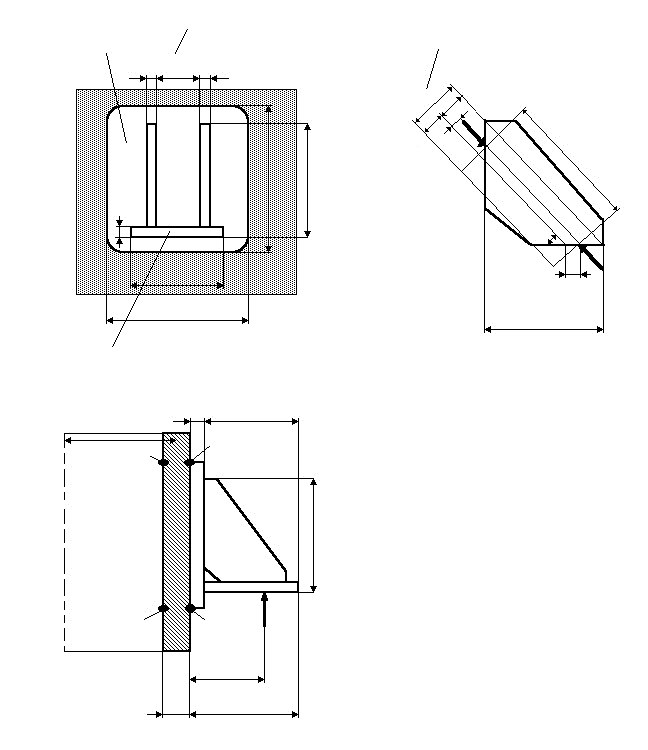
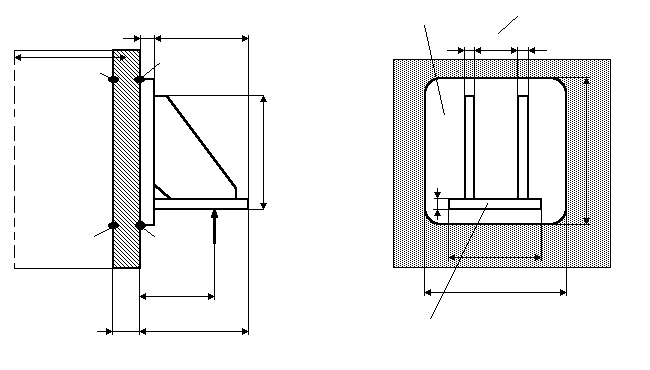
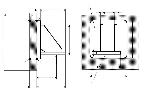
Standard and calculation basis: AD 2000 S3/4: 2001-09
Calculation workflow
- Define the load case and total loads: For the selected load case (operation, test, erection), the design pressure at the bracket plane, the design temperature, the total moments in the bracket plane and the maximum total weight load are entered.
- Distribute the loads to the brackets: From the number of brackets and the total loads, the governing single-bracket force is determined. Moments cause an uneven distribution; the most heavily loaded bracket governs, and the loss of uniform load sharing (e.g. due to erection inaccuracy) must also be covered conservatively.
- Verify the vessel wall at the introduction point: With its lever arm, the bracket force acts on the cylindrical wall as a force-moment combination and generates local membrane and bending stresses there. These are superposed with the pressure stresses and compared with the allowable stress; a reinforcing plate enlarges the effective introduction area.
- Size the bracket components: The bearing plate, the web plate and the reinforcing plate are verified for the bracket force and the offset moment. The material, the nominal design strength and the safety factors for operation, test and the load case determine the allowable stresses; allowances for wall thickness undertolerance and corrosion reduce the load-carrying thicknesses.
- Dimension the anchor bolts: For the anchorage, the required core diameter of the anchor bolts is determined from the uplift or horizontal force components of the most unfavourable load case.
Input quantities
| Quantity | Symbol | Unit |
|---|---|---|
| Load case | Lastfall | – |
| Design pressure at the bracket plane | p | bar |
| Design temperature | T | °C |
| Total moments in the bracket plane | M | N·mm |
| Maximum total weight load | Gd | N |
| Minimum total weight load | Gz | N |
| Number of brackets | n | – |
| Initial tightening force of the bolts | Fv | N |
| Comment | Bemerkung | – |
| Cylinder wall thickness | se | mm |
| Outside vessel diameter | Da | mm |
| Eccentricity of the bracket force | ap | mm |
| Thickness of the reinforcing plate | sv | mm |
| Height of the reinforcing plate | hv | mm |
| Width of the reinforcing plate | bv | mm |
| Thickness of the support plate | sa | mm |
| Depth of the supporting plate | ta | mm |
| Width of the supporting plate | ba | mm |
| Distance between web plates | ab | mm |
| Number of web plates | ns | – |
| Web plate thickness | ss | mm |
| Length of equivalent web plate | ls | mm |
| Width of equivalent web plate | bs | mm |
| Eccentricity of the web plate force | as | mm |
Calculated results
| Quantity | Symbol | Unit |
|---|---|---|
| Load case | Lastfall | – |
| Comment | Bemerkung | – |
Calculation options
Load case
Operation · Testing · Assembly · Exception
Frequently asked questions
How does a moment arise at the bracket even though only weight acts?
The support reaction acts on the bearing plate at a distance (lever arm) from the vessel wall. This offset generates a bending moment that is introduced into the wall via the web plate as a force couple – tension at the top, compression at the bottom. The further the support point lies from the wall, the larger the moment and the local wall loading become. Short lever arms and sufficiently tall web plates ease the verification.
When does the bracket need a reinforcing plate on the vessel wall?
When the local bending stresses in the wall from the bracket force, superposed with the pressure stresses, exceed the allowable values – typical for thin-walled vessels, high filling weights or a small number of brackets. The reinforcing plate distributes the load introduction over a larger area. It should be rolled to the wall curvature and welded all around; the corners are radiused to avoid stress concentrations.
Can the wall calculation of S3/4 also be used for other attachments?
Yes. The calculation of the vessel wall under a locally introduced force-moment combination applies generally to additional forces without an opening in the wall – for example for brackets of platforms, pipe supports or lifting points. As soon as the load is introduced via a nozzle with an opening, the verifications for nozzle loads (AD 2000 S3/0 in conjunction with B9) must be carried out instead.
How many brackets are sensible, and may all be assumed to carry equally?
Two to four brackets are common, occasionally eight. Statically indeterminate arrangements only share the load evenly if the support levels line up exactly; erection tolerances can load individual brackets considerably more. The code accounts for this by considering the most heavily loaded bracket – when entering the number of brackets, the load distribution actually ensured (e.g. by shims during alignment) should be taken into account.