ASME – Pressure vessel calculations
Understand, connect and review shell, head and nozzle calculations.
Package overview and detailed teaching case with real program images, original example files and traceable comparison values.
No chapter found. Try another search term.
Chapter 01From component to traceable assessment
A pressure vessel is a shared design task: shell, heads, nozzles, flanges and supports must match the same load cases and material assumptions. SOL ALPHA provides individual calculation modules for these tasks. This handbook shows how to select the right assessment, transfer data safely and interpret results so that a change in design pressure does not silently bypass one chapter of the calculation.
The continuous example is a small vessel with a cylindrical shell, an elliptical head and a set-on nozzle. Start with a saved example file, review the three individual modules UG27, UG32 and UG37, then connect two pressures and one required thickness. Changing pressure from 1 to 2 MPa lets you follow the entire relationship: required shell thickness rises, the head calculation follows pressure, and the nozzle requires more area while the shell reserve decreases.
On your first pass, read sequentially through the results comparison. For a familiar calculation, the UG27, UG32 and UG37 chapters lead directly to the necessary decisions. The package map positions all 51 configured members; the field reference explains the important numbers.
Chapter 02Establish code, division and edition
The package name “ASME VIII” identifies a selection group. It does not promise that every member calculates under the same division. The inspected descriptions assign UG27, UG32 and UG37 to Section VIII Division 1, edition 2025. A187/A188/A189 and A416 name Division 2. ANSI and B311 belong to piping codes; TEB and TEB1 name TEMA, and ELFP names Roark. These methods cannot be exchanged merely because they appear together in one package.
The official ASME description of BPVC Section VIII Division 1 covers fabrication, inspection, testing and certification as well as design. A successful thickness or area result does not cover those further tasks. The ASME certification overview distinguishes the divisions and their certification scopes.
Record three separate statements
- Project basis: Which section, division, edition and explicitly permitted supplementary methods apply to the contract?
- Module basis: Which method and edition does the selected module name? The map records the inspected local descriptions; some entries name older editions.
- Calculation version: Which application and plugin executed the actual assessment? The documentation source revision does not automatically establish the version of a running installation.
This book reviews public ASME scope descriptions and the implemented module sources. The complete licensed code text, including every exception, was not checked edition by edition. Where an example explains an equation, it identifies the documented software basis; a number in this book does not replace the applicable code provision.
Back to top ↑Chapter 03Which module do I need?
The 51 entries match the stored ASME package configuration. This table helps select an engineering task. It promises neither current entitlement nor a thoroughly tested execution of every token. An unestablished method is identified explicitly so that a similar module name does not lead to the wrong selection.
| Module / display | Task, prerequisite data and result | Registered basis | Learning route |
|---|---|---|---|
| A187 A4187 | U-tube tubesheet Tube/shell pressure, temperatures and tube field → mechanical tubesheet assessment under VIII-2. | ASME BPVC VIII-2, A4187 2025 | Role in the workflow |
| A188 A4188 | Fixed tubesheet Tube/shell system and restraint → fixed tubesheet assessment under VIII-2. | ASME BPVC VIII-2, A4188 2025 | Role in the workflow |
| A189 A4189 | Floating tubesheet Floating-head construction and load cases → tubesheet assessment under VIII-2. | ASME BPVC VIII-2, A4189 2025 | Role in the workflow |
| ABDR | Tees with additional loads Pipe geometry and external loads → stresses. The registered B31.3 edition is 1980. | ANSI/ASME B31.3-1980 Edition | Role in the workflow |
| AFL | Bolted flanges Flange, bolts, gasket and pressure/temperature → loads and flange assessment under VIII-1 App. 2. | ASME BPVC VIII Division 1 App. 2: 2023 | Role in the workflow |
| AFLT | Flange dimensions Nominal size, Class and type → B16.5 dimensions; then review strength and rating. | ASME B16.5 | Role in the workflow |
| AN3F Annex 3-F | Fatigue curves Stress differences and material → allowable cycles under the stated VIII-2 method. | ASME BPVC 2017, Section VIII-Division 2, Annex 3-F; Part 5 | Role in the workflow |
| ANSI ASME B31.3 | Process piping Straight pipe, bend or branch and loading → B31.3 piping assessment. | ASME B31.3 2022 | Role in the workflow |
| ANXB AnnexB | Furnace calculation temperature Thermal furnace data → calculation temperature; metadata name Annex B without a uniquely identified standard. | Not uniquely specified | Role in the workflow |
| AP09 ASME App. 9 | Jacket closure Jacket/vessel geometry and pressure differences → closure assessment under VIII-1 App. 9. | ASME BPVC VIII-1 Mandatory Appendix 9 2019 Edition | Role in the workflow |
| AP14 | Flat head with central opening Head and opening geometry → special method for a large single central opening. | ASME VIII-1 Mandatory Appendix 14 | Role in the workflow |
| AP26 | Bellows expansion joint Expansion-joint geometry and loading → stated Appendix 26 assessment; retain cycle requirements. | ASME BPVC VIII-1 Appendix 26, 2019 Edition | Role in the workflow |
| APA | Tube-to-tubesheet joint Joint type and material data → allowable joint loads; not a complete tubesheet assessment. | ASME BPVC VIII Nonmandatory Appendix A, Edition 2019 | Role in the workflow |
| APY | Metal-contact flanges Flange contact outside the bolt circle → applicable Appendix Y assessment. | ASME Appendix Y, 2023 Edition | Role in the workflow |
| ASEQ | Seismic loads Site, structure and masses → IBC 2012 / ASCE 7-2010 loads; establish the site basis separately. | IBC 2012 & ASCE 7-2010 | Role in the workflow |
| ASWD | Wind loads Site/exposure data and geometry → wind loads under the stated ASCE 7-05 basis. | ASCE 7-05 | Role in the workflow |
| ATB | Bolted spherically dished cover Pressure, geometry and bolting → Appendix 1-6 assessment. | ASME VIII APPENDIX 1, 1-6 2025 Edition | Role in the workflow |
| B169 | Reducer dimensions Nominal dimensions and type → B16.9 dimensions on the stated 1986 basis. | ASME/ANSI B16.9: 1986 | Role in the workflow |
| B311 ASME B31.1 | Power piping Straight pipes, bends and reinforcement → B31.1 assessment. | ASME B31.1:2022 | Role in the workflow |
| DICH | Gasket properties Gasket selection and service conditions → input properties for flange assessment. | AD 2000 B7 & ASME VIII | Role in the workflow |
| ELFP | Elliptical flat plate Plate dimensions, support and load → Roark stresses; no standalone VIII-1 assessment established. | Roark's formulas for stress and strain | Role in the workflow Configured; unresolved in the two Web registers. |
| FANY FANY Obsolete | Historical fatigue assessment Obsolete; XML identifies AN3F as its replacement. Interpret historical results on the registered VIII-2 2013 basis; review the replacement for new selections. | ASME BPVC VIII-2, Appendix 5, 5-110: 2013 | Role in the workflow |
| SEGB | Curved and mitered bends Pipe/segment geometry and internal pressure → B31.3 assessment. | ASME B31.3: 2022 | Role in the workflow |
| TEB | TEMA tubesheet Exchanger type and load data → mechanical TEMA tubesheet assessment, registered basis 1999. | TEMA Section 5 | Role in the workflow |
| TEB1 | Historical TEMA tubesheet route Tubesheet data → RCB-2.21, 1978 method; reconcile applicability with the project code. | TEMA Section 5 - RCB-2.21: 1978 | Role in the workflow |
| TEB2 | Pipe bends and tees under moments Pipe geometry and moments → B31.3 stress assessment. | ASME B31.3:2022 | Role in the workflow |
| U99N UG99 | Test pressure Included components, operating/test properties and load case → hydrostatic/pneumatic test quantities. | ASME BPVC VIII-1 UG-99 & UG-100: 2025 | Role in the workflow |
| UBC | Historical seismic route Site, structure and mass → UBC 1997 seismic loads; distinguish from ASEQ. | Uniform Building Code UBC: 1997 | Role in the workflow |
| UG27 | Shell under internal pressure Cylinder/sphere geometry, pressure, material and joint efficiencies → thickness demand and component pressure. | ASME BPVC VIII-1 UG-27 & Appendix-1: 2025 | Detailed guide and case |
| UG28 | Shell under external pressure Geometry, support length, material and external pressure → stability assessment; not negative UG27 internal pressure. | ASME BPVC VIII-1 UG-28 & Appendix 1: 2025 | Role in the workflow |
| UG29 | Stiffening rings External-pressure shell and ring section → ring requirements; return geometry to UG28. | ASME BPVC VIII-1 UG-29: 2025 | Role in the workflow |
| UG32 | Head and cone under internal pressure Design type, pressure, geometry and material → head/cone thickness and junction results. | ASME BPVC VIII-1 UG-32 & Appendix-1: 2025 | Detailed guide and case |
| UG33 | Formed head under external pressure Head type, geometry, material and external pressure → separate stability assessment. | ASME BPVC VIII-1 UG-33 & Appendix-1: 2025 | Role in the workflow |
| UG34 | Flat heads and covers Support, attachment, openings and pressure → applicable flat plate assessment. | ASME BPVC VIII-1 UG-34 & UG-39: 2025 | Role in the workflow |
| UG37 | Openings and nozzles Parent-shell demand, nozzle, welds and opening location → area/weld/neck checks. | ASME BPVC VIII-1 UG-37: 2025 | Detailed guide and case |
| UHXA UHXa | VIII-1 U-tube tubesheet U-tube exchanger and mechanical load cases → UHX-12 route. | ASME BPVC VIII-1, UHX-12: 2023 | Role in the workflow Configured; unresolved in the two Web registers. |
| UHXC UHXc | VIII-1 floating tubesheet Floating-head exchanger and load cases → UHX-14 route. | ASME BPVC VIII-1, UHX-14: 2021 | Role in the workflow Configured; unresolved in the two Web registers. |
| UXBN UHXb 2022 | VIII-1 fixed tubesheet Fixed tubesheet exchanger and restraint → UHX-13 route. | ASME BPVC VIII-1, UHX-13: 2021 | Role in the workflow |
| ZCF4 ZCF47 | VIII-2 cover flange Cover flange and internal/external pressure → method 4.7.5.3; display name ZCF47. | alternative rules 4.7.5.3, ASME Sec. VIII Div. 2 Ed2025 | Role in the workflow |
| ZICK | Saddle supports Vessel geometry, weight and saddle spacing → Zick/WRC support assessment. | WRC Saddle Zick | Role in the workflow |
| A416 | VIII-2 flanges Flange, bolts and load cases → VIII-2 flange assessment; select for the correct division. | ASME BPVC VIII-2, A416 2025 | Role in the workflow |
| UHXB | Configured additional tubesheet token No module description in the inspected XML. Do not treat as an alias of UXBN; establish identity before use. | Not uniquely specified | Role in the workflow Configured; unresolved in the two Web registers. |
| A431 | Configured token A431 Metadata contain only generic labels; no technically established selection route in this edition. | Not uniquely specified | Role in the workflow |
| A432 | Configured token A432 Metadata contain only generic labels; identify method and design types before use. | Not uniquely specified | Role in the workflow |
| A45H A452_nozzle_head | Display A452_nozzle_head XML mapping established; exact method/edition not established here. Do not assume interchangeability with UG37. | Not uniquely specified | Role in the workflow Configured; unresolved in the two Web registers. |
| A45S A452_nozzle_shell | Display A452_nozzle_shell XML mapping established; exact method/edition not established here. Do not assume interchangeability with UG37. | Not uniquely specified | Role in the workflow Configured; unresolved in the two Web registers. |
| A461 | Configured token A461 Only generic XML configuration; establish scope before project selection. | Not uniquely specified | Role in the workflow Configured; unresolved in the two Web registers. |
| A801 | Configured token A801 Only generic XML configuration; no assessment scope inferred from the number. | Not uniquely specified | Role in the workflow Configured; unresolved in the two Web registers. |
| MDMT | Minimum design metal temperature Material group, governing thickness and conditions → MDMT/impact-test assessment for the selected variant. | ASME BPVC VIII-1 UCS-66 / UCS-66.1 / UCS-68 / UHA-51: 2025 | Role in the workflow |
| FWEL | Opening attachment welds Attachment detail and thicknesses → UW-16 execution conditions; complements the UG37 area assessment. | ASME BPVC Sec. VIII Div. 1, UW-16 & Figure UW-16.1: 2025 | Role in the workflow |
| ABRA | Brackets on cylinders/spheres Local geometry and forces/moments → VIII-2 / WRC 537 assessment. | ASME BPVC Section VIII Division 2: 2025, 4.15.5 & Part 5 Table 5.6; WRC Bulletin 537 | Role in the workflow |
Chapter 04Prepare the design data
Start with a data sheet outside the three calculation masks. A useful entry records quantity, value, unit, source, load case and scope. One pressure may be agreed for the entire vessel, while hydrostatic loading depends on component location. Temperature is a design assumption, not automatically the operating temperature currently measured. Geometry needs inside/outside and as-new, corroded or measured-condition labels.
- Load cases: Record design pressure, allowable temperature combinations, pressure differences, liquid levels, test conditions, start-up/shutdown and possible vacuum.
- Geometry: Tie diameters, actual minimum thickness, head depth, nozzle dimensions and attachment detail to a drawing revision.
- Materials: Track product specification, supply condition, thickness range, temperature-dependent properties and code eligibility separately for shell, head, nozzle, pad and bolts.
- Fabrication: Do not derive weld type, examination extent, joint efficiencies, forming, tolerances and allowances from a generic default.
- Additional loads: Flag self-weight, attachments, piping forces, moments, wind, seismic effects and cycles as further assessment tasks.
The teaching case uses 150 °C for the three main components, initially 1 MPa design excess pressure and 0 MPa hydrostatic head. Shell outside diameter and actual thickness are 600 mm and 6 mm. All explicitly entered corrosion and thickness allowances are zero. This makes the connection effects easier to recognise; it does not justify zero allowances for an actual design.
The main review principle is that equal numbers do not yet constitute a shared data source. Three manually entered temperatures of 150 °C remain three separate inputs. The checked chain connects only the fields listed in the connections chapter.
Back to top ↑Chapter 05Find your way around the application
Open the learning case in a separate practice project through File → Open. The project tree must contain UG27 design type 1, UG32 design type 1 and UG37 design type 4. Select each chapter in turn. Review design type, pressure mode, unit, material selection and messages before changing values. For a new project, add modules through the ASME package selector and select the corresponding design type; a complete fresh cold start was not repeated for this book.
Masks use collapsible engineering sections. UG27 moves from pressure and material through shell geometry to thicknesses and pressures. UG32 adds the head form and its radii or depths. UG37 contains parent shell, nozzle, optional reinforcement, areas and weld forces. A collapsed section is not necessarily empty. Expand the downstream sections when reviewing results.
Right-click a numeric field to open its variable menu. The recording uses Bookmark and Link. In a connection dialog, read the target token and field number first, then the source. This prevents a numerically plausible thickness from being attached to the wrong meaning. General operating help explains entry, releasing, fixing and goal seeking; this book explains the engineering quantity affected in each case.
Chapter 06Units, inputs and calculated values
1 MPa equals 10 bar and 1 N/mm². Changing 1 to 2 MPa therefore changes 10 to 20 bar. The small unit beside the numeric field is part of the input. These modules retain some old internal labels saying “in bar” although the teaching case displays MPa. When reproducing it, check field number, physical quantity and visible unit together.
Excess pressure, absolute pressure and hydrostatic head have different meanings. In the checked connection, UG27:V32 denotes design pressure excluding head in MPa; UG32:V123 and UG37:V181 denote the same quantity with the unit key MPa(p). This specific case therefore used “Show all variables”. The non-identical unit-key symbol has not been removed from the image. An absolute fluid-property pressure cannot be connected this way without the necessary conversion.
Recognise a value's role
A known input, calculated result, fixed value and connection are different states. In the recording, prescribed values appear as ordinary input fields and calculated values have a colour indication; the thickness bookmark additionally has a green mark. Use colour for orientation only because styling and theme can change. Check field state and the variable menu. An old visible number may remain after an incomplete recalculation.
Historical preparation entered recipe values as ordinary user inputs. Result checks confirmed that output values were known and calculated. After linking, pressure targets were read as known bound values. This observation does not establish that every field can be released for arbitrary inverse calculations.
When changing a unit or input role, finish confirming the entry and wait for calculation completion. Record the starting value before experimenting. If results are unexpected, restore unit and role before changing a second physical parameter.
Back to top ↑Chapter 07Material, joint efficiencies and allowances
The demonstration material has local identifier 1232 and is displayed as 1.4571(P) – X 6 CrNiMoTi 17-12-2. Its regression entry identifies hot-worked plate and EN/AD references. This does not establish ASME eligibility. Use that selection to reproduce the historical numbers; a real ASME project needs the required product specification and defensible allowable stresses under its applicable basis.
A material code is not a stress value. The property follows from material, temperature, product/thickness range and selected method. The historical UG32 result image shows an operating allowable stress S of 206 MPa. That is an observation from this example, not a general ASME table value for 1.4571. Replacing the material requires a new technical basis for the entire comparison chain; the old results cease to be targets.
The shell treats E and Ec separately. They belong to different joint/stress directions. An example value of one does not automatically establish an examination extent. The permissible assignment follows the specific joint detail and agreed code edition. Casting quality factors can have a separate role; do not change these selection states incidentally to obtain an apparently better thickness.
Actual and effective wall
For the simple teaching case, t0 = te − c1 − c2 = 6 − 0 − 0 = 6 mm. These 6 mm are actual thickness; pressure-required thickness is a separate calculated field. Increasing c2 reduces the effective remaining wall and may change the corroded geometry. Ordered nominal thickness is also not automatically the minimum thickness present everywhere after forming.
UG37 separates shell, nozzle and pad materials and allowances. Identically named entries in three groups remain separate data. A thicker reinforcement cannot be fully credited beyond its effective limits; a different material may also change the credit through strength ratios.
Back to top ↑Chapter 08Load the prepared vessel
Download starting case · tutorial-vessel-a.sol · Download the saved connected revision
Both downloads are unchanged SOL demonstration files from the approved tutorial. The first is the unlinked starting case at 1 MPa. The second is the connected revision saved at 2 MPa during that recording. Historical verification confirmed reopening the starting file; this handbook work did not repeat reopening the saved final revision.
- Open the starting file in a separate practice project. After loading, confirm that no restore or calculation error remains open.
- Select UG27 and check 1 MPa, 0 MPa hydrostatic head, 150 °C, 600 mm outside diameter, 6 mm actual thickness and the demonstration material.
- Select UG32. The head has 600 mm outside diameter, 156 mm outside depth and 6 mm actual thickness. Calculated inside diameter is 588 mm.
- Select UG37. The nozzle is set-on, without a separate pad, with 60.3 mm outside diameter and 5 mm wall. The parent shell is cylindrical.
- Compare the six starting results in the results table. If a result differs, restore the starting state before adding any connection.
Every explicitly entered input
The following tables are the complete input lists from the checked preparation recipes. They contain user inputs and the initially transferred thickness entered once by hand. Unlisted internal selection, default and calculation states come from the unchanged starting archive. The archive is therefore the reproducible entry point; these tables alone do not claim a fully tested cold start.
UG27
| Field | Input | Unit / selection |
|---|---|---|
| UG27:V32 Design pressure excluding head | 1 | MPa |
| UG27:V34 Hydrostatic head | 0 | MPa |
| UG27:V16 Calculation temperature | 150 | °C |
| UG27:V17 Material selection | 1232 · 1.4571(P) | — |
| UG27:V21 Actual wall thickness | 6 | mm |
| UG27:V22 Thickness allowance c1 | 0 | mm |
| UG27:V23 Corrosion allowance c2 | 0 | mm |
| UG27:V5 Joint efficiency | 1 | — |
| UG27:V45 Circumferential joint efficiency | 1 | — |
| UG27:V24 Outside diameter | 600 | mm |
UG32
| Field | Input | Unit / selection |
|---|---|---|
| UG32:V123 Design pressure excluding head | 1 | MPa(p) |
| UG32:V125 Hydrostatic head | 0 | MPa(p) |
| UG32:V3 Calculation temperature | 150 | °C |
| UG32:V21 Actual head thickness | 6 | mm |
| UG32:V22 Thickness allowance | 0 | mm |
| UG32:V23 Corrosion allowance | 0 | mm |
| UG32:V6 Cylinder outside diameter | 600 | mm |
| UG32:V70 Crown outside depth | 156 | mm |
| UG32:V14 Head joint efficiency | 1 | — |
| UG32:V11 Head material | 1232 · 1.4571(P) | — |
UG37
| Field | Input | Unit / selection |
|---|---|---|
| UG37:V3 Internal/external pressure selector | Internal pressure | — |
| UG37:V210 Parent-shell shape | cylindrical | — |
| UG37:V5 Required shell thickness without allowances; link target | 1.4534885 | mm |
| UG37:V181 Design pressure excluding head | 1 | MPa(p) |
| UG37:V183 Hydrostatic head | 0 | MPa(p) |
| UG37:V2 Calculation temperature | 150 | °C |
| UG37:V92 Shell outside diameter | 600 | mm |
| UG37:V4 Shell thickness without allowances | 6 | mm |
| UG37:V93 Actual axial shell length | 150 | mm |
| UG37:V9 Shell joint efficiency | 1 | — |
| UG37:V6 Shell material | 1232 · 1.4571(P) | — |
| UG37:V187 Shell thickness allowance | 0 | mm |
| UG37:V188 Shell corrosion allowance | 0 | mm |
| UG37:V16 Nozzle outside diameter | 60.3 | mm |
| UG37:V197 Nozzle joint efficiency | 1 | — |
| UG37:V22 Nozzle material | 1232 · 1.4571(P) | — |
| UG37:V13 Nozzle thickness allowance | 0 | mm |
| UG37:V14 Nozzle corrosion allowance | 0 | mm |
| UG37:V40 Actual external projection | 80 | mm |
| UG37:V12 Actual nozzle thickness | 5 | mm |
| UG37:V20 Outside attachment weld thickness | 5 | mm |
| UG37:V175 Shell/nozzle groove weld thickness | 5 | mm |
The later connection replaces UG37's initial V5 = 1.4534885 mm input with a link to UG27:V7. Shell wall V4 = 6 mm remains independent. The external nozzle projection of 80 mm is actual geometry; the projection credited in the result may be smaller.
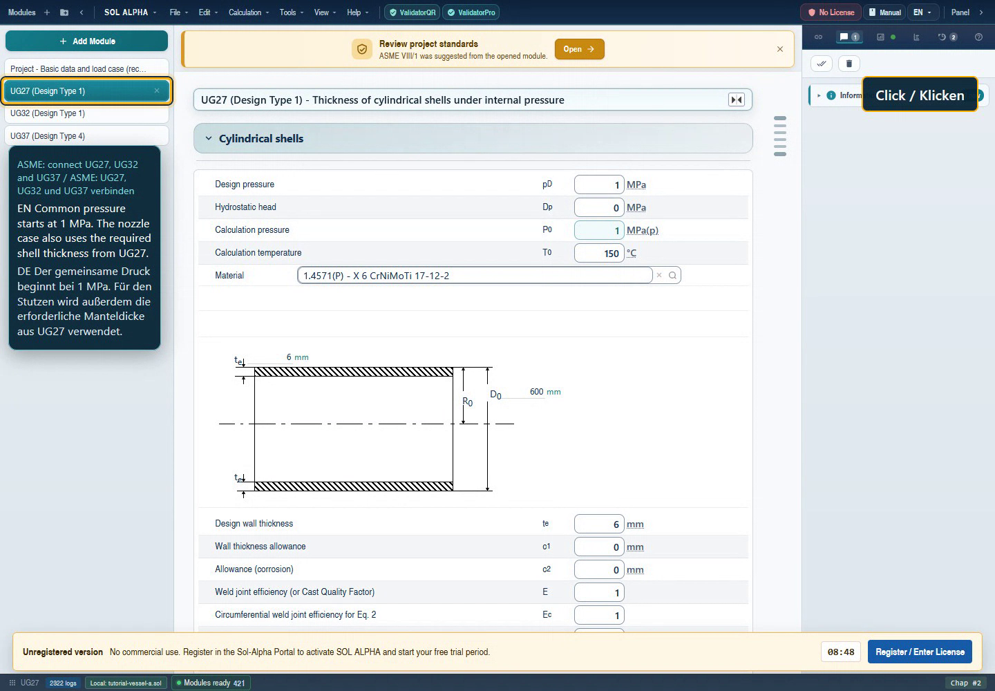
- Check design pressure, hydrostatic head, calculation pressure and temperature separately.
- 600 mm outside diameter and 6 mm actual wall define geometry.
Unchanged original frame from the approved learning video recorded on 6 September 2026. Messages and historical labels remain visible; numbered highlights are HTML elements. Open original.
Chapter 09UG27: Read the shell assessment correctly
UG27 assesses required thickness and allowable component pressure for a cylindrical or spherical shell under internal pressure. Design type 1 is the teaching-case cylinder; type 2 is a spherical shell. Use the dedicated UG28 route for external pressure; entering negative internal pressure does not replace stability assessment. Length, support and shape imperfections play different roles there.
A useful first workflow
- Select design type and establish design pressure V32, hydrostatic head V34 and temperature V16.
- Select material V17 and review the associated allowable stress V4. Material eligibility must be established independently of obtaining a known number.
- Enter actual thickness V21, allowances V22/V23 and the two joint efficiencies V5/V45. The teaching case uses 6 mm, two zero allowances and two efficiencies of one.
- Establish the outside-diameter route V24 = 600 mm. Check the resulting radii: R0 = 300 mm and, with 6 mm effective wall, R = 294 mm.
- Review method applicability, the several thickness rows, pressures, minimum thickness and messages. Then read the separate opening-reference section.
Why 1.5 mm and 1.4534885 mm are both valid readings
Starting values UG27:V6 = 1.5 mm and UG27:V7 = 1.4534885 mm belong to different result rows. V7 is the outside-radius pressure demand. V6 includes the module's selected combination and minimum-thickness limit. A minimum rule creates a flat result range: a small pressure change can change pressure demand while the combined result initially remains at 1.5 mm. This observed minimum is the demonstration module's state, not a universal restatement of all UG-16 minimum thicknesses.
After pressure increases to 2 MPa, V6 = 2.8710938 mm and V7 = 2.9013538 mm. The result image shows the radius-based approaches alongside each other. This is not a rounding difference. Actual wall remains 6 mm, so inside radius remains 294 mm. Copying only the first number loses the connection to its equation.
A traceable arithmetic check
The thin-shell outside-radius equation documented in the source is t(R0) = P·R0/(S·E + 0.4·P). With S = 206 MPa, E = 1, R0 = 300 mm and P = 2 MPa, it gives 600/206.8 = 2.901354 mm. The inside-radius expression P·R/(S·E − 0.6·P) gives 588/204.8 = 2.871094 mm. This direct evaluation explains the two readings; it does not verify the material property or every selection and validity condition.
Which thickness belongs to the opening?
UG27 also provides V25 for the separate opening reference thickness at E = 1. V25, V7, V6 and V21 are therefore not interchangeable “thicknesses”. The historical operating case explicitly links V7 to UG37:V5. Record that source relationship in the experiment. For another project, establish the opening reference thickness under the applicable method and governing geometry. In particular, changing E or allowances requires reviewing the transferred quantity again.
The displayed allowable pressure belongs to the shell under its assumptions. It is not the allowable pressure of the complete vessel. Head, opening, flange, test state and additional loading can impose other limits. For inverse work, use the separate thickness demand as a target chapter.
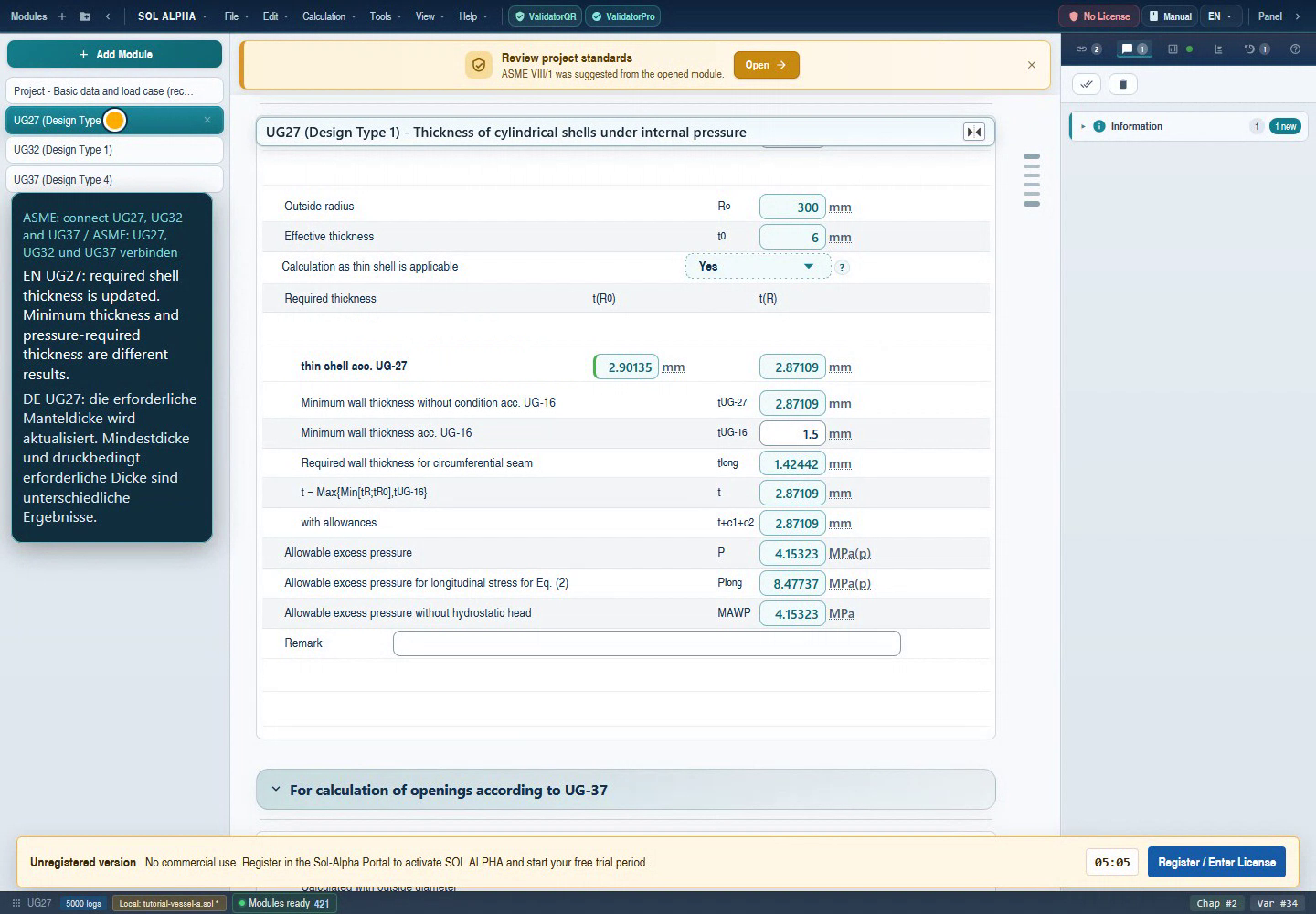
- Read outside-radius and inside-radius approaches separately.
- Distinguish pressure demand, minimum thickness and combined result.
- Allowable pressures refer to this shell.
Unchanged original frame from the approved learning video recorded on 6 September 2026. Messages and historical labels remain visible; numbered highlights are HTML elements. Open original.
Chapter 10UG32: Head form, geometry and junctions
UG32 extends internal-pressure assessment to formed heads, cones and cone-to-cylinder junctions. Establish the correct form before entry. An elliptical head with the wrong depth and a Kloepper head with a matching diameter do not describe the same construction. This overview deliberately separates the six registered design types:
| Design type | Construction task | Establish before selection |
|---|---|---|
| 1 | Elliptical head | Inside/outside depth and ratio D/(2h). |
| 2 | Torispherical, Kloepper/Korbbogen/hemispherical head | Crown, knuckle and specific shape selection. |
| 3 | Cone without knuckle | Cone angle and largest governing diameter. |
| 4 | Cone with knuckle | Knuckle radius; the older English register label is ambiguous. |
| 5 | Large-end cone junction | Shell, cone, reinforcement and axial additional loads. |
| 6 | Small-end cone junction | Geometry and forces at this junction, separately from the large end. |
Understand the elliptical teaching case
Enter the shared pressure/temperature basis and review material and E. The prepared case uses outside head diameter V6 = 600 mm, actual thickness V21 = 6 mm and outside crown depth V70 = 156 mm. With no allowances, this gives inside diameter D = 588 mm and inside depth h = 150 mm. Consequently D/(2h) = 1.96. The calculation geometry is therefore not an exact internal 2:1 ellipsoid.
The source uses shape factor K = [2 + (D/(2h))²]/6, giving 0.9736. Do not inadvertently substitute K = 1 in a hand check merely because someone informally called the head “2:1”. With 2 MPa, D = 588 mm, S = 206 MPa and E = 1, the documented expression P·D·K/(2·S·E − 0.2·P) explains the demand of 2.781714 mm.
At 1 MPa, the pressure-dependent E=1 row V72 gives 1.3901819 mm, while V15 includes the module's minimum-thickness limit and displays 1.5 mm. At 2 MPa both happen to be 2.7817147 mm. Agreement in this state does not make their meanings identical. Actual thickness remains 6 mm; with zero allowances, the required-thickness-with-allowances row has the same number only because the allowances are zero.
An opening in the head needs more than the same pressure
Below the general results, UG32 includes opening reference thicknesses at E=1, a separate central crown-region row and an equivalent spherical outside diameter. V72 and V73 represent different approaches; V132 is derived geometry. Opening location and the effective region belong to the decision. This example's nozzle is on the cylindrical shell, so it contains no checked thickness connection from UG32 to UG37.
What other design types add
For torispherical heads, crown and knuckle radii determine the form; a named head type does not make its geometric ratios interchangeable. Review geometric conditions and any additional strength or buckling rows produced by the selected method. The source mask contains such conditions; the elliptical pressure experiment does not establish their behaviour for all forms.
Cone junctions add reinforcement areas and axial additional loads at the large or small end, alongside shell and cone thicknesses. These fields describe separate components and load contributions. A purely pressure-required cone thickness does not automatically complete the junction assessment. Obtain an unambiguous joint drawing showing ring, knuckle and force introduction before calculating.
UG33 is the corresponding selection route for external pressure. A UG32 internal-pressure experiment establishes neither vacuum stability nor every possible load case. Comparisons with AD or EN heads also require identical physical inputs and their respective rules; matching head-form names alone is insufficient.
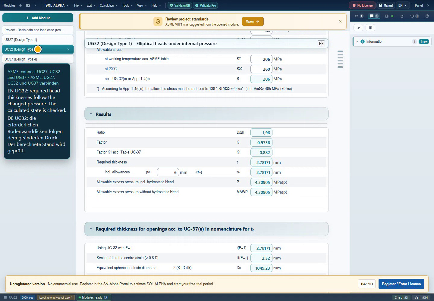
- D/(2h)=1.96 and K=0.9736 match the actual inside dimensions.
- Demand is 2.78171 mm; actual wall remains 6 mm.
- Opening reference thickness and equivalent geometry are separate results.
Unchanged original frame from the approved learning video recorded on 6 September 2026. Messages and historical labels remain visible; numbered highlights are HTML elements. Open original.
Chapter 11UG37: Opening, area reserve and welds
An opening removes material from the pressure-retaining shell. UG37 assesses required and credited areas, nozzle thickness and attachment-weld forces, among other quantities. A favourable area utilisation is only one result group. The teaching case has a single set-on nozzle without an additional pad on a cylindrical parent shell:
| Design type | Nozzle/opening type | Distinguishing feature |
|---|---|---|
| 1 | Protruding with reinforcement | Internal projection and separate pad. |
| 2 | Protruding without reinforcement | No separate pad; still assess available reserves. |
| 3 | Set-on with reinforcement | Set-on detail, outside welds and pad. |
| 4 | Set-on without reinforcement | This is the teaching-case design type. |
| 5 | Adjacent nozzles under UG-42 | Two openings, ligament and overlapping regions. |
Prepare parent shell and nozzle separately
The parent shell uses V92 = 600 mm outside diameter and V4 = 6 mm effective thickness without allowances. V93 = 150 mm is actual available axial shell length. Pressure, temperature and material must match the underlying shell assessment. V5 is required shell thickness without allowances and is later linked in the experiment. That connection must not replace actual thickness V4.
Nozzle inputs are V16 = 60.3 mm outside diameter, V12 = 5 mm actual thickness and V40 = 80 mm external projection. Zero nozzle allowances give an inside diameter of 50.3 mm. V20 and V175 are set to 5 mm in the example. They belong to different attachment-weld fields; they are not a generally permissible weld specification. Design type 4 uses no separate pad.
Why utilisation rises faster than pressure
At 1 MPa, required V35 = 73.110466 mm² and available credited V38 = 374.0912 mm² give historical utilisation V91 = 19.543488 %. At 2 MPa, demand rises to 145.9381 mm² and utilisation to 49.19959 %. The available credited area decreases at the same time: increased required shell thickness V5 consumes previously available shell reserve. Utilisation therefore does not simply double with pressure.
An explanatory evaluation for this simple case is 50.3 mm × 1.4534885 mm = 73.11047 mm². After the pressure change, 50.3 × 2.9013538 = 145.93810 mm² reproduces the observed demand. This arithmetic check explains the thickness connection here. General area assessment includes further geometry, joint, material and credit conditions and must not be reduced to this product for arbitrary openings.
Actual length is not automatically effective length
The result image shows only 12.5 mm credited external projection although the actual projection is 80 mm. Shell length is limited too: the image shows a limit length of 25.15 mm. Extending the nozzle to, for example, 100 mm therefore need not add credited area. First examine the limiting geometric region, then deliberately change a quantity that affects that region.
Read the other result groups completely
- Nozzle neck: Review minimum and junction thicknesses, including the module's UG-45 results. An area ratio below 100 % does not replace the neck requirement.
- Attachment welds: Read forces and allowable forces for each joint detail. A negative intermediate number visible in the image is not interpreted as a general “negative load is safe” rule; the associated defined comparisons and messages govern.
- Reinforcement areas: Distinguish required area, shell reserve and other credited areas. “No pad” does not mean “no credited reserve of any kind”.
- Adjacent openings: Design type 5 requires separate review of ligament and overlapping regions. Do not mentally credit the same area in full twice for overlapping assessments.
The sources contain messages for overloaded welds, exceeded area utilisation, insufficient ligament and combined membrane/bending stresses. The learning video checks the area path; it did not deliberately trigger every condition. The Appendix 1-7 region is partly blank in the result image; blank fields do not establish a passed additional assessment.
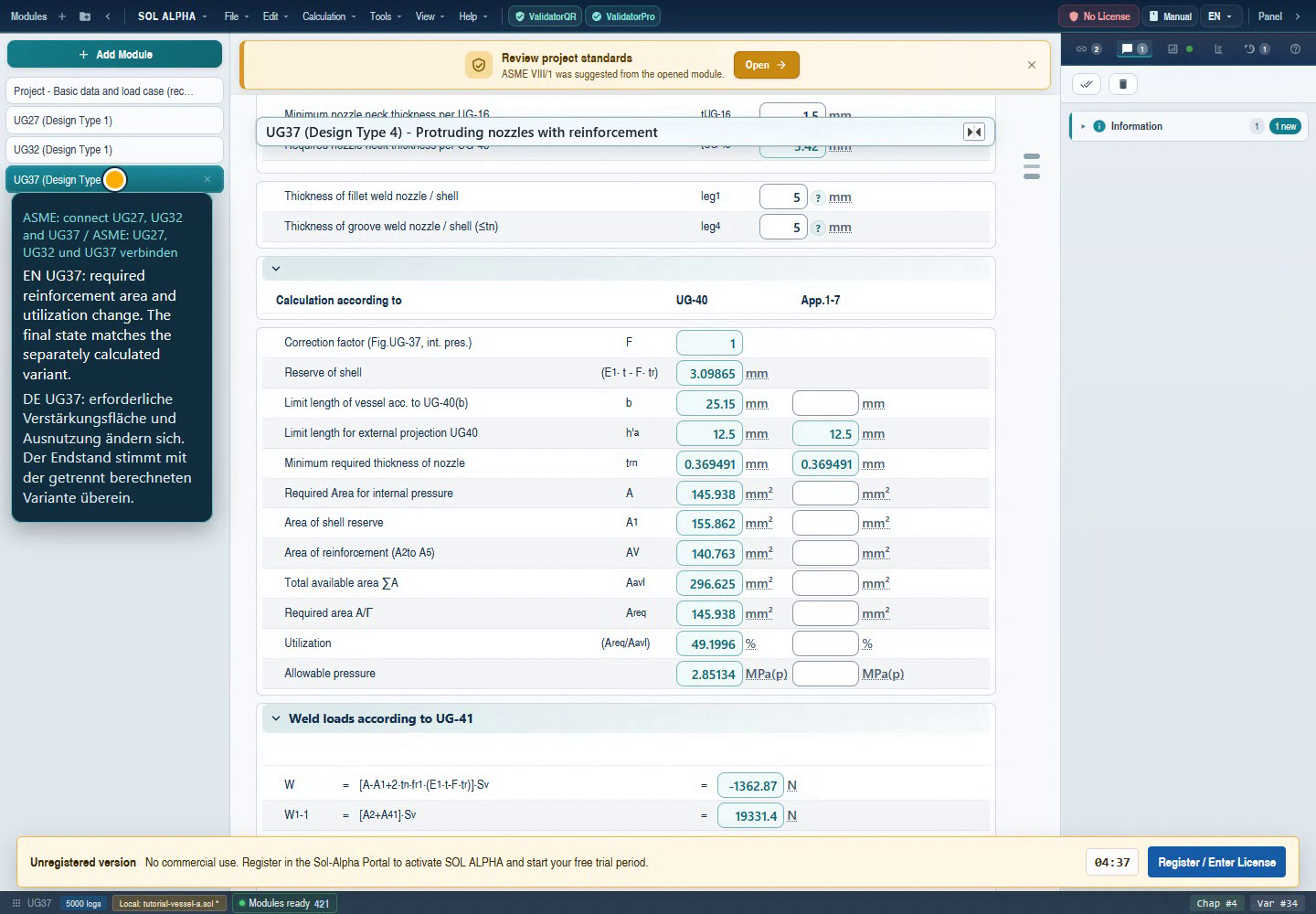
- Shell reserve and credited lengths have their own limits.
- Read required and available area together: 49.1996% utilisation.
- Attachment-weld forces belong to an additional result group.
Unchanged original frame from the approved learning video recorded on 6 September 2026. Messages and historical labels remain visible; numbered highlights are HTML elements. Open original.
Chapter 12Create three deliberate connections
The connection list is short and explicit: UG27:V32 → UG32:V123, UG27:V32 → UG37:V181 and UG27:V7 → UG37:V5. The first two transfer design excess pressure excluding head. The third transfers a calculated shell thickness demand. The diagram describes the case's data relationships; it is not a program screenshot.
Conceptual diagram. Only these three links belong to the checked operating case; geometry, temperature, materials and actual walls remain separate inputs.
- In UG27, open the V32 variable menu and bookmark it. The source must show 1 MPa.
- In UG32, open the V123 variable menu and select Link. Check the target line UG32 V123. If MPa/MPa(p) filtering hides the source, use “Show all variables” after checking the quantities. Explicitly select UG27 V32.
- Repeat for UG37 V181. Both targets must still display 1 MPa and indicate that they are linked.
- In UG27, add a bookmark for V7, the outside-radius thickness demand. Link it to UG37 V5. Check mm → mm and the value 1.4534885 mm.
- Read back all three targets. A closed selection dialog alone does not establish that the intended connection was applied.
The interface may describe the link as bidirectional. Arrows in the teaching diagram describe our chosen operating direction: only source UG27:V32 is edited. Editing a linked target may propagate back, depending on binding. Avoid prescribing both source and target until their roles are clear.
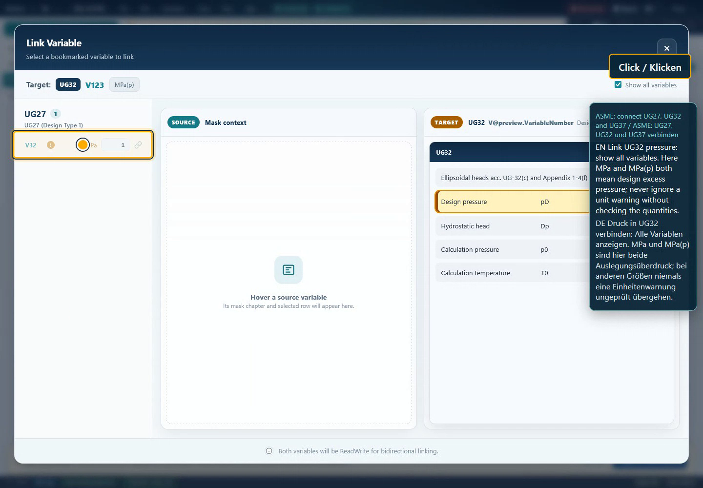
- Target UG32:V123 and unit MPa(p).
- Source UG27:V32. Unit keys are not identical here.
- Select Show all variables only after checking the quantities.
Unchanged original frame from the approved learning video recorded on 6 September 2026. Messages and historical labels remain visible; numbered highlights are HTML elements. Open original.
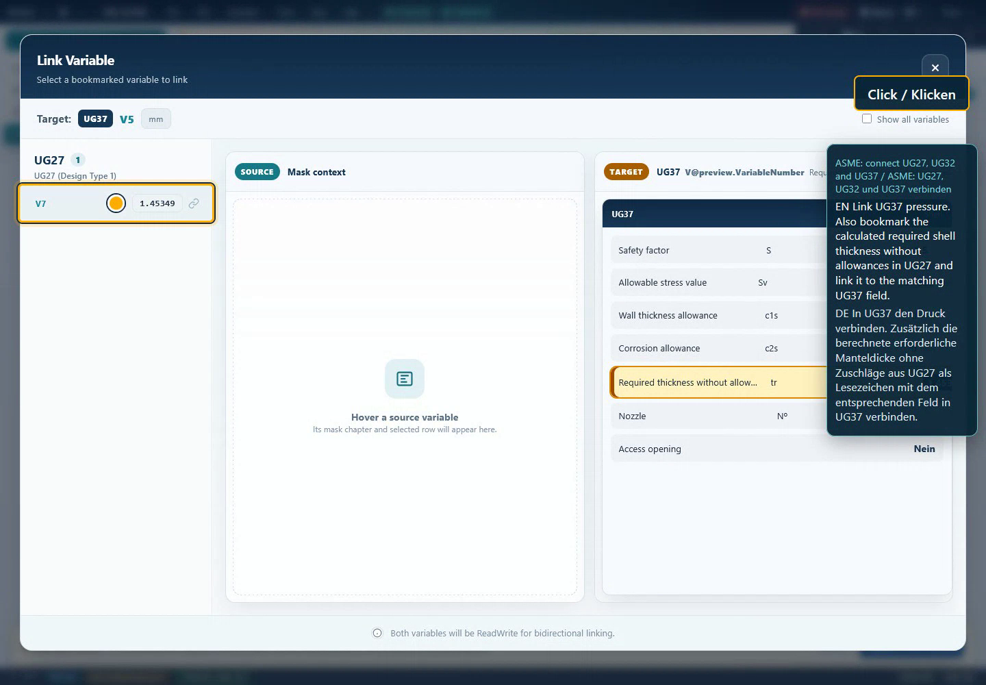
- Target UG37:V5, required parent-shell thickness.
- Source UG27:V7, 1.45349 mm in the historical starting state.
Unchanged original frame from the approved learning video recorded on 6 September 2026. Messages and historical labels remain visible; numbered highlights are HTML elements. Open original.
Chapter 13Change pressure and follow the effect
The objective is a deliberate revision of the common pressure. Save your practice state before the experiment. Then change only UG27:V32 from 1 to 2 MPa. Confirm the entry, wait for calculation completion and inspect messages. In this step, leave actual walls, geometry, materials and temperature at their documented values.
UG27's pressure-required thickness rises; its actual 6 mm wall stays the same. UG32 must now also show 2 MPa design pressure. UG37 needs two updates: V181 receives 2 MPa and V5 receives the newly calculated 2.9013538 mm. Checking pressure alone is insufficient because a stale V5 thickness would distort both credited shell reserve and required area.
The next chapter's reference values were compared in the historical video against a target state previously obtained by separate input edits. Both routes used the same calculation environment. This comparison tests transfer and updating; it is not an independent implementation of the ASME equations.
Returning and trying further revisions
To return, reopen the unchanged starting archive in a practice project. Alternatively, change V32 back to 1 MPa in your connected copy and compare the same six starting results and connections. This is a recommended check, not a fresh execution during handbook authoring. If you next change 150 °C, deliberately update temperature in every affected chapter: temperature was not linked here.
Watch the complete operating workflow
English program interface with bilingual captions. Only video requires Internet; instructions, images and examples are stored locally. Open video directly.
Back to top ↑Chapter 14Compare and interpret results
The following values come from the approved video comparison of 6 September 2026. The starting archive was reopened, three connections were created and the 2 MPa revision was compared with target states entered separately in the same calculation environment. The table deliberately identifies fields rather than using a generic term such as “wall thickness”.
| Field | Meaning | 1 MPa | 2 MPa | Unit |
|---|---|---|---|---|
| UG27:V6 | Combined thickness demand | 1.5 | 2.8710938 | mm |
| UG27:V7 | Outside-radius thickness demand | 1.4534885 | 2.9013538 | mm |
| UG32:V15 | Head thickness demand | 1.5 | 2.7817147 | mm |
| UG32:V72 | Opening thickness demand E=1 | 1.3901819 | 2.7817147 | mm |
| UG37:V35 | Required area | 73.110466 | 145.9381 | mm² |
| UG37:V91 | Area utilisation | 19.543488 | 49.19959 | % |
The recorded comparison tolerances were max(0.0001; |target| × 0.00001), in the stated unit. These tight tolerances identify the same software state. They are neither manufacturing tolerances nor engineering safety margins. The interface rounds to fewer digits; compare the same field quantity and unit.
Interpret the three responses together: the shell shows rising pressure demand, the head follows the same pressure revision, and the nozzle loses reserve because its required parent-shell thickness is transferred too. Matching one number in one module is insufficient. Also read attachment-weld checks, neck thicknesses, geometric conditions and open messages.
Before comparing allowable component pressures, establish hydrostatic reference, load case and included assessments. A complete result needs a complete list of governing limits. The three learning modules alone do not cover that full scope.
Back to top ↑Chapter 15Thickness demand as a target: deliberate inverse work
“Which pressure gives 3 mm demand?” is a different question from “Which actual wall is present?”. In a separate UG27 copy, consider outside-radius thickness demand V7 as a target. The target is 3 mm; outside radius 300 mm, S = 206 MPa, E = 1, hydrostatic head 0 MPa and actual wall 6 mm remain fixed for this arithmetic exercise.
Rearranging the outside-radius expression documented in the source gives P = S·E·t/(R0 − 0.4·t). Here, P = 206 × 3 / (300 − 1.2) = 2.068273 MPa. This is a newly evaluated equation check, not a freshly observed UI solver run. It identifies which quantities must be free and which must remain fixed.
- Save a separate experiment copy and, if necessary, disconnect links to other chapters so that the exercise does not cause unintended project changes.
- Use the application's goal-seeking feature with target UG27:V7 = 3 mm and variable UG27:V32. Check that the dialog varies pressure.
- If an input-role exchange is offered, check that the pressure input is released and exactly the target quantity is prescribed. Keep V21 = 6 mm as actual wall.
- Compare the pressure found with the equation above, result V7 and the other conditions. Reaching a target number does not eliminate the remaining thickness/pressure conditions.
- Restore ordinary roles: P as input, V7 as output. A forward calculation with the resulting pressure must reproduce the target demand.
Goal seeking typically changes a driving input, whereas a persistent role exchange changes the chapter's input/output arrangement. Distinguish these workflows. Minimum-thickness limits make inversion ambiguous: V6 = 1.5 mm can hold over a whole pressure range. Use the well-defined pressure demand V7 for this teaching exercise and remain within the valid equation range.
Back to top ↑Chapter 16Connections, child calculations and test pressure
The teaching case's three manually created links are only one form of cooperation. The inspected module sources also contain module-managed child chapters and interfaces. An additional UG27 chapter needed by UG37 for a nozzle or parent-shell requirement is not automatically the main shell chapter you created. Identify owner, task and data direction every time.
For certain thickness checks, UG37 creates or reuses a managed UG27 child for internal pressure or UG28 for external pressure. The source route sets the relevant parent-shell shape, manages chapter identity and may hide the child. Changing pressure type handles associated chapters that are no longer appropriate. This is an established internal source route; the learning video did not exercise every pressure mode or chapter transition. Avoid imposing extra inputs directly inside an automatically managed child.
UG27 and related components implement an interface for U99N. Among other things, it manages whether a module participates in the test-pressure assessment, allowable stresses for operating and test conditions, and chapter identity. An available interface does not mean that a newly opened U99N automatically includes every intended load case completely. Review included components, load case, temperature-dependent properties and governing limit.
The chain's shared design pressure is not a prescribed test plan. When hydrostatic or pneumatic testing is required, use the appropriate basis, component list and dedicated test functions. The historical experiment changed design pressure only; this book does not claim a complete U99N test-pressure run.
Back to top ↑Chapter 17Continue toward the complete vessel
After the learning chain, inventory the components and load cases actually present. This is an engineering sequence, not a mandatory solver order. A later finding often sends you back to an earlier dimension. Record every change to shared assumptions along the way.
| Task | Useful continuation | Question before transfer |
|---|---|---|
| External pressure / vacuum | UG28, UG29, UG33 | Are support, length, form and material basis defined? |
| Flanges and gaskets | AFL or A416 / APY / ZCF4; DICH; AFLT | Which division, contact arrangement, bolt and gasket assumptions apply? |
| Tubesheets | UHXA / UXBN / UHXC or A187 / A188 / A189 | Which exchanger type, division and shared load-case combination apply? |
| Connections and additional loads | FWEL, ABRA, piping/stress modules | Are forces/moments, reference point and weld details complete? |
| Supports and site loads | ZICK, ASWD, ASEQ or UBC | Which actual site basis and load case have been agreed? |
| Fatigue and low temperature | AN3F/FANY; MDMT | Are cycle history or governing temperature/thickness conditions established? |
| Testing and completion | U99N plus complete assessment list | Are all governing components and test conditions included? |
For a heat exchanger, thermal design provides important geometry and temperature data. WTS Package – Heat exchanger calculation explains that task. Thermally adequate area does not establish mechanical adequacy of tubesheet, shell, tubes or joints. Conversely, a mechanical thickness revision can affect heat transfer, pressure drop and thermal expansion. Deliberately reconcile the two data revisions.
The selection group contains historical methods and incompletely described identifiers. FANY is explicitly marked obsolete and replaced by AN3F; it helps interpret older calculations. The package map identifies these limits in each affected entry. A missing name is not permission to infer a standard from a token. This first package edition provides the full selection overview and one detailed core case; it does not replace 51 standalone module handbooks.
Back to top ↑Chapter 18Save, reopen and document
Save a revision after all intended inputs have been confirmed and calculations have finished. Use a name that identifies state and change, such as “ASME learning case – pressure 2 MPa – connected”. Record the three connections alongside it. A correctly named file may still contain the wrong state; check its content.
- Before saving, record pressure, geometry, material, temperature, allowances and the six comparison results.
- Save the project in the intended SOL format. The downloadable example files in this book preserve their original bytes.
- Open your saved copy in a separate practice project. Review design types and fields again, including all three connection mappings.
- Compare numbers and roles. A restored known value must still behave as a connection after a deliberate source change.
- Inspect messages and all relevant result groups before producing a report.
The report should include project code and edition, drawing revision, load case, units, material/property basis, actual and required dimensions, connection sources, governing results and open issues. State utilisation with its definition, for example “UG37 required area / available credited area”. A percentage without a reference quantity cannot be reviewed meaningfully.
The handbook print function produces a readable reference with questions expanded. It does not replace the project calculation report. Text, images and example archives also work offline in the complete local handbook folder; embedded video comes from the existing external media host.
Back to top ↑Chapter 19Common questions and troubleshooting
The head pressure stays at 1 MPa.
Check whether UG32:V123 is linked to UG27:V32. Linking calculation pressure to design pressure would be a different relationship. Read source and target in the connection dialog and inspect calculation state.
The pressure source is missing from the dialog.
In the known case, the interface filters MPa and MPa(p) differently. First verify design excess pressure excluding head, then use Show all variables. Do not generalise this to incompatible pressure types.
UG37 shows new pressure but old utilisation.
Also check V5: after the change it must receive 2.9013538 mm from UG27:V7. Then check complete calculation and messages. Unchanged demand despite correctly updated inputs needs separate investigation.
Why is required thickness initially 1.5 mm?
A minimum-thickness limit governs in the observed module state. Read UG27 V6/V47/V48 or UG32 V15/V72 separately. Pressure-required thickness can vary before exceeding that limit.
Why do UG27 V6 and V7 differ afterwards?
They belong to different result approaches and combinations. The example includes inside radius 294 mm and outside radius 300 mm. Do not treat this as rounding or silently change the thickness source.
Can I always link UG27 V7 to UG37?
No. This recording establishes the operating case with E=1 and zero allowances. UG27 contains separate opening reference value V25. The appropriate quantity depends on code conditions, geometry approach and joint efficiencies.
The nozzle should be in the head instead of the shell.
Re-establish parent-shell form, opening location and the appropriate UG32 opening reference values including equivalent geometry. Copying the cylindrical connection chain unchanged is inappropriate.
Why does the elliptical head show 1.96 instead of 2?
The case specifies outside dimensions. Internally D=588 mm and h=150 mm give D/(2h)=1.96. Inside and outside shape ratios differ when wall thickness is finite.
Is material 1232 an ASME material?
1232 is a local selection identifier for the demonstration material. Its inspected description names EN/AD references. ASME eligibility was not established here; neither the identifier nor a displayed property replaces that verification.
Can I change temperature only in the shell?
Temperature is not linked in this case. Allowable stresses of head, shell and nozzle must match their actual temperatures. Update every affected chapter for a shared temperature revision.
Additional projection does not add area.
Compare actual with credited projection. The image credits only 12.5 mm out of 80 mm. Further length outside the limit does not improve that area contribution.
Area utilisation is below 100 %, but a weld is overloaded.
Area replacement and force transfer through welds are separate checks. Review weld type, effective thickness, material property and associated force. The weld message remains relevant until its specific condition is satisfied.
Appendix 1-7 fields are blank.
The fields may be inactive or uncalculated in the current state. A blank region is not a passed assessment. Check whether the method is required and active for the selected opening.
How do I handle adjacent openings?
Review design type 5 and both openings. Ligament, spacing and overlapping credited regions belong to the combined assessment. Two successful individual openings do not establish adjacent-opening adequacy.
The interface asks to release a quantity.
An additional input can overconstrain the calculation. Decide which engineering quantity is now unknown. Do not release an arbitrary field; save the starting state and change only the intended role.
Can negative internal pressure represent vacuum?
Use the suitable external-pressure route: UG28 for the shell and UG33 for the head. Stability depends on geometry and support, among other factors; changing the sign of an internal-pressure field does not perform that assessment.
Can I adopt the smallest visible MAWP?
Only after reviewing which components, load cases and pressure references are covered. Missing or uncalculated assessments cannot supply a limit. An incomplete list of component values does not establish complete vessel MAWP.
The SOL file opens with different values.
First check filename, starting versus final revision, active design types, material data and units. Record application version and messages. Do not repair the saved file by writing presumed expected results back into calculated fields.
Why does the old UG37 header name another design type?
The original recording contains a known title inconsistency. Design type 4 and the prepared scenario describe the set-on nozzle without a pad. The image is not retouched; verify form and geometry in your own project.
Where are videos available offline?
Text, images and example files belong to the local handbook folder. Video stays on the existing media host and needs Internet access. The fully described learning workflow and numeric tables remain usable without video.
Chapter 20Terms for the next calculation step
| Term | Meaning in the workflow |
|---|---|
| Design pressure | Specified pressure input; retain hydrostatic head and reference location separately. |
| Calculation pressure | Pressure used at the component, including its associated additional contributions. |
| MAWP | Maximum allowable working pressure; meaningful only with explicit component/overall scope and pressure reference. |
| Allowable stress S | Method- and temperature-dependent property; not interchangeable with tensile strength or a material code. |
| Joint efficiency E | Factor governing the specific joint/stress direction; requires a technical basis. |
| Actual thickness | Wall physically present; distinguish it from required calculation thickness. |
| Effective thickness | Wall after deductions required by the method. |
| Opening reference thickness tr | Required parent-shell thickness used in opening assessment; record its source and assumptions. |
| Pad | Additional reinforcement element; its entire geometric area is not automatically credited. |
| Credited area | Load-bearing area included under the applicable limits and material/joint conditions. |
| Utilisation | Ratio of a defined demand to its associated capacity; always read the actual definition. |
| Child module | A calculation managed by a parent module for a separate subtask. |
| Connection | Shared data relationship; equal manually entered numbers are not a connection. |
| Revision | Coherent documented state of inputs, links, results and project basis. |
Chapter 21Look up fields and results
Selected operating fields with reviewed translations. Numbers always belong to their module identifier. Units refer to the teaching case or the quantity concerned; check the field unit in a different display. An old internal label containing “in bar” does not prove that the current value is displayed in bar. Conditional cone, pad and adjacent-opening fields appear only for their relevant design type.
UG27
| Field | Meaning | Unit in the learning context |
|---|---|---|
| UG27:V1 | Effective thickness without allowances | mm |
| UG27:V2 | Outside radius | mm |
| UG27:V4 | Allowable stress | MPa |
| UG27:V5 | Joint efficiency | — |
| UG27:V6 | Combined required thickness including minimum | mm |
| UG27:V7 | Outside-radius thickness demand t(1) | mm |
| UG27:V8 | Thick-shell outside-radius thickness demand | mm |
| UG27:V9 | Allowable component excess pressure | MPa(p) |
| UG27:V14 | Calculation pressure including head | MPa(p) |
| UG27:V16 | Calculation temperature | °C |
| UG27:V17 | Material selection | — |
| UG27:V20 | Required thickness including allowances | mm |
| UG27:V21 | Actual wall thickness | mm |
| UG27:V22 | Thickness allowance c1 | mm |
| UG27:V23 | Corrosion allowance c2 | mm |
| UG27:V24 | Outside diameter | mm |
| UG27:V25 | Separate opening reference thickness, E=1 | mm |
| UG27:V32 | Design pressure excluding head | MPa |
| UG27:V34 | Hydrostatic head | MPa |
| UG27:V36 | Allowable pressure excluding head | MPa |
| UG27:V38 | Inside radius | mm |
| UG27:V39 | Inside-radius thickness demand | mm |
| UG27:V43 | Thin-shell method applicable | — |
| UG27:V44 | Circumferential-joint / longitudinal-stress thickness demand | mm |
| UG27:V45 | Circumferential joint efficiency | — |
| UG27:V46 | Allowable pressure from longitudinal stress | MPa(p) |
| UG27:V47 | Module minimum thickness under UG-16 | mm |
| UG27:V48 | Pressure-required thickness before minimum rule | mm |
UG32
| Field | Meaning | Unit in the learning context |
|---|---|---|
| UG32:V1 | Calculation pressure including head | MPa(p) |
| UG32:V3 | Calculation temperature | °C |
| UG32:V4 | Thickness without allowances | mm |
| UG32:V5 | Corroded cylinder inside diameter | mm |
| UG32:V6 | Cylinder outside diameter | mm |
| UG32:V7 | Crown inside radius | mm |
| UG32:V8 | Cone half-angle | ° |
| UG32:V9 | Knuckle radius | mm |
| UG32:V11 | Head material | — |
| UG32:V13 | Head allowable stress | MPa |
| UG32:V14 | Head joint efficiency | — |
| UG32:V15 | Required head/cone thickness | mm |
| UG32:V16 | Allowable excess pressure including head | MPa(p) |
| UG32:V19 | Crown inside depth | mm |
| UG32:V21 | Actual head thickness | mm |
| UG32:V22 | Thickness allowance | mm |
| UG32:V23 | Corrosion allowance | mm |
| UG32:V24 | Geometry ratio D/(2h) | — |
| UG32:V25 | Geometry factor K | — |
| UG32:V29 | Axial additional load, large end | N/mm |
| UG32:V30 | Axial additional load, small end | N/mm |
| UG32:V61 | Required reinforcement area, large end | mm² |
| UG32:V62 | Required reinforcement area, small end | mm² |
| UG32:V65 | Required thickness including allowances | mm |
| UG32:V70 | Crown outside depth | mm |
| UG32:V72 | Opening reference thickness E=1 | mm |
| UG32:V73 | Separate crown region E=1 | mm |
| UG32:V123 | Design pressure excluding head | MPa(p) |
| UG32:V125 | Hydrostatic head | MPa(p) |
| UG32:V127 | Allowable pressure excluding head, component 1 | MPa(p) |
| UG32:V132 | Equivalent spherical outside diameter for UG37 | mm |
| UG32:V133 | Module minimum thickness | mm |
UG37
| Field | Meaning | Unit in the learning context |
|---|---|---|
| UG37:V1 | Calculation pressure including head | MPa(p) |
| UG37:V2 | Calculation temperature | °C |
| UG37:V3 | Internal/external pressure selector | — |
| UG37:V4 | Shell thickness without allowances | mm |
| UG37:V5 | Required shell thickness without allowances; link target | mm |
| UG37:V6 | Shell material | — |
| UG37:V8 | Shell allowable stress | MPa |
| UG37:V9 | Shell joint efficiency | — |
| UG37:V12 | Actual nozzle thickness | mm |
| UG37:V13 | Nozzle thickness allowance | mm |
| UG37:V14 | Nozzle corrosion allowance | mm |
| UG37:V15 | Nozzle thickness without allowances | mm |
| UG37:V16 | Nozzle outside diameter | mm |
| UG37:V17 | Corroded nozzle inside diameter | mm |
| UG37:V18 | Internal nozzle projection | mm |
| UG37:V19 | Required nozzle thickness without allowances | mm |
| UG37:V20 | Outside attachment weld thickness | mm |
| UG37:V22 | Nozzle material | — |
| UG37:V25 | Pad thickness without allowances | mm |
| UG37:V26 | Pad outside diameter | mm |
| UG37:V28 | Pad material | — |
| UG37:V31 | Available shell thickness reserve | mm |
| UG37:V32 | Credited shell limit length | mm |
| UG37:V33 | Credited external nozzle projection | mm |
| UG37:V35 | Required area under internal pressure | mm² |
| UG37:V36 | Shell reserve area | mm² |
| UG37:V37 | Other credited reinforcement areas | mm² |
| UG37:V38 | Total available credited area | mm² |
| UG37:V39 | Governing required area | mm² |
| UG37:V40 | Actual external projection | mm |
| UG37:V56 | Ligament length of adjacent openings | mm |
| UG37:V91 | Area utilisation | % |
| UG37:V92 | Shell outside diameter | mm |
| UG37:V93 | Actual axial shell length | mm |
| UG37:V175 | Shell/nozzle groove weld thickness | mm |
| UG37:V181 | Design pressure excluding head | MPa(p) |
| UG37:V183 | Hydrostatic head | MPa(p) |
| UG37:V185 | Allowable pressure excluding head | MPa(p) |
| UG37:V187 | Shell thickness allowance | mm |
| UG37:V188 | Shell corrosion allowance | mm |
| UG37:V189 | Actual shell thickness with allowances | mm |
| UG37:V191 | Minimum nozzle demand under UG27 | mm |
| UG37:V196 | Required nozzle junction thickness under UG-45 | mm |
| UG37:V197 | Nozzle joint efficiency | — |
| UG37:V201 | Module minimum thickness under UG-16 | mm |
| UG37:V210 | Parent-shell shape | — |
Chapter 22Sources, evidence and limits
Editorial review date: 7 September 2026. The frozen source snapshot records source paths, hashes, package members and field labels. Web: main13.0 / 1cd12e8b173ba72aa5c95c98a14772b7ee537997. All-Dev: fix-iteration/v10 / 40606b705b2df95e550ffef5e98ab733ccc66229. Review covered package registration, module descriptions, all registered core masks and selected equation, state and child routes for UG27, UG32 and UG37.
The public ASME BPVC VIII-1 product description establishes the code's scope and lists edition 2025. The official certification overview describes certification scope, distinct from the calculation task. Both sources accessed on 7 September 2026. Equation explanations in this book were checked against the stated module source revision; the complete licensed code text was neither reproduced nor fully audited.
Historical runtime evidence · Image provenance · Scope and file hashes. Recording date is 6 September 2026; frames were extracted on 7 September. This is not a new calculation. The exact historical plugin build was not independently identified. Original files and images remain unchanged.
The connected pressure revision was compared with separate input edits in the same calculation environment. This book does not claim a complete cold start, new live run, reopening the saved final revision, UI inverse run, every design type, all weld/adjacent-opening conditions, Desktop parity or complete ASME compliance. Direct equation checks for UG27, UG32 and the simple area case explain selected numbers; they do not replace independent method validation.
The map positions all 51 package members. Eight identifiers are unresolved in the two Web registers, and some further generic descriptions leave the specific method open. Each affected entry carries that information. This package edition contains one continuous UG27/UG32/UG37 core case; it does not complete separate standalone manuals for all members.
Back to top ↑