EN 13445 – Pressure vessel calculations
Understand internal pressure, external pressure and openings through one connected EN07/EN08/EN09 example.
Engineering foundations, complete package map, detailed teaching case and real program captures. Numerical evidence comes from the checked tutorial of 6 September 2026.
No chapter found. Try another search term.
Chapter 01Using this handbook
You want to calculate a pressure vessel and understand which assessment answers which question. This handbook takes you from a shared design data sheet to a connected example: a cylindrical shell is assessed under internal pressure, under a separate external-pressure load case, and at a single opening. You then change its diameter and trace the consequences through all three calculation chapters.
Start with the engineering task and package map. For your first practical pass, load the prepared starting case, check its data and follow Connections. The three module chapters then explain why the results change. Keep the field reference and troubleshooting sections for subsequent work. Search accepts module names, concepts and field numbers such as SUIP V26.
EN07, EN08 and EN09 are the visible names. Their internal identifiers are SUIP, SUEP and NOIS. A connection dialog or saved file may show these identifiers. This handbook gives both together; a field number without its module identifier is ambiguous. For example, V26 is the outside diameter in SUIP but a geometry ratio in NOIS.
This edition maps all 44 configured package members and provides detailed guidance for the three core modules. It is a substantial package handbook; this does not mean 44 individual module manuals have been completed. The displayed results and original images come from the checked and approved tutorial of 6 September 2026. They have been reviewed for this book and are not presented as a new runtime execution. The complete local book, including images and examples, works without Internet access; the supporting video requires a connection.
Back to top ↑Chapter 02One vessel, several assessment questions
A component has shared geometry but can be loaded in different ways. Internal pressure acts differently on a shell from external overpressure. An opening changes the local load-carrying cross-section. Supports, piping forces, wind, temperature differences and load cycles introduce further tasks. The engineering problem therefore determines the modules; the order of a selection list does not determine the required assessment scope.
In the teaching case, EN07 represents the undisturbed cylindrical shell. EN08 uses the same outside diameter but evaluates stability under its own external pressure. EN09 assesses an opening in that shell under internal pressure. The three results mean different things: required thickness, allowable external pressure and opening utilisation cannot simply be substituted for one another.
Before calculation, prepare a component and load-case list. Assign geometry, materials, temperatures and loads to each shell course, head, transition, flange and connection. Identify which data are actually shared. Two chapters can name the same material while requiring different governing temperatures, thickness ranges or strength values.
A “fulfilled” message concerns the conditions actually evaluated in that module. It does not establish that your component and load-case list is complete. The teaching project contains neither a complete real vessel nor all operating, test, erection and transport conditions. Use it to learn controlled data management and interpretation, then add the missing assessments deliberately for an actual construction.
Back to top ↑Chapter 03Package map: all 44 identifiers
The following 44 identifiers come from API package configuration. Display names and tasks were checked against the module catalogue. This describes configured scope, not live licensing. The tubesheet load-case tokens ending in S are explained in XML but absent as standalone modules from both Web registration lists.
| Identifier / display | Task | Required data, use and handoff | Learning path |
|---|---|---|---|
| 134S / EN13.4S | U-tube tubesheet load cases | Load-case chapters generated from EN13.04; first define the parent exchanger and its cases. Do not infer independent Web availability from this package token. | Orientation in this package |
| 135S / EN13.5S | Fixed-tubesheet load cases | Load-case chapters generated from EN13.05, carrying the parent task. Review generated chapters after changing the parent module. | Orientation in this package |
| 136S / EN13.6S | Floating-tubesheet load cases | Load-case chapters generated from EN13.06; read them in the floating-head exchanger context. Registration is not evidence of a separately tested module. | Orientation in this package |
| 1613 / EN16.13 | Vertical vessels with ring supports | Supply vessel geometry, support ring and loads; assess the support together with global loading. | Orientation in this package |
| 168N / EN16.08 | Horizontal vessels on saddles | Define saddle positions, vessel dimensions and loading; assess local support effects in addition to pressure-wall thickness. | Orientation in this package |
| BFUS / EN16.11 | Vertical vessels on legs | Leg geometry, arrangement and loads need their own specifications; reconcile results with the structural model. | Orientation in this package |
| E134 / EN13.04 | U-tube exchanger tubesheets | Prepare tube layout, tubesheet, channel and pressure cases; assess the selected U-tube route with its generated cases. | Orientation in this package |
| E135 / EN13.05 | Fixed exchanger tubesheets | Define both exchanger sides and temperature/pressure conditions; account for restraint and load-case relationships of fixed tubesheets. | Orientation in this package |
| E136 / EN13.06 | Floating-head exchanger tubesheets | Use floating-head geometry, tube layout and load cases; do not carry over fixed-tubesheet boundary conditions. | Orientation in this package |
| E164 / EN16.04 | Local loads on spherical-shell nozzles | Supply nozzle geometry and forces/moments at a spherical connection; supplements the pressure-opening assessment. | Orientation in this package |
| E165 / EN16.05 | Local loads on cylindrical-shell nozzles | Define connection geometry and oriented load components; do not confuse results with NOIS pressure utilisation. | Orientation in this package |
| E166 / EN16.06 | Line loads | Define loaded length, shell dimensions and load model; local load distribution needs its own assessment. | Orientation in this package |
| E169 / EN16.09 | Horizontal vessels with ring supports | Assess horizontal-vessel ring support with its geometry and loads; distinguish it from saddle support. | Orientation in this package |
| EFL / EN11 | Flanges | Collect flange, bolt and gasket data plus load cases; shell-pressure assessment does not establish flange adequacy. | Orientation in this package |
| EK17 / EN17 | Simplified fatigue life | Prepare load cycles and component data; check applicability of the simplified route before interpreting results. | Orientation in this package |
| EN10 | Flat ends | Assign circular or non-circular flat ends with support and edge moment; the catalogue explicitly excludes tubesheets. | Orientation in this package |
| EN12 | Bolted dished ends | Assess end geometry and bolting under their own loads; distinguish these from a welded standard head. | Orientation in this package |
| EN15 | Rectangular pressure vessels | Define non-circular geometry and wall support; cylinder equations are not a substitute. | Orientation in this package |
| EN18 | Detailed fatigue life | Compile detailed stress and load-cycle data; use where assessment needs exceed the simplified route. | Orientation in this package |
| EN20 | Stiffened flat walls and ends | Assess wall and stiffener geometry together; do not represent a stiffener merely as extra wall thickness. | Orientation in this package |
| EN22 | Wind loads | Supply site and geometry assumptions for wind; assign loads to the complete structural assessment. | Orientation in this package |
| ENAF | External pressure with excess out-of-roundness | Use measured shape deviation and geometry; a separate route for out-of-roundness exceeding tolerance. | Orientation in this package |
| ENAJ | Alternative tubesheet method | The catalogue names asymmetric tubesheets and larger untubed regions; review applicability of the Annex J route. | Orientation in this package |
| ENAO | Physical properties of steel | Identify material class and temperature for physical properties; one property does not establish full material approval. | Orientation in this package |
| ENTP / EN16.10 | Vertical vessels on support brackets | Supply bracket arrangement, connection geometry and loads; consider local and global support behaviour together. | Orientation in this package |
| ENZA / EN16.12 | Vertical vessels on skirts | Define skirt/vessel geometry and load combinations; trace the load path to the installation support. | Orientation in this package |
| LUG / EN16.07 | Lifting lugs | Define lug geometry, load and lifting direction; document lifting as its own engineering task. | Orientation in this package |
| NOIS / EN09 | Openings in shells | Supply shell, opening type, local lengths and pressure; single-opening lesson and result interpretation provided. | Detailed guide + example |
| PDEN | Test pressure | Assemble test conditions and associated design data; do not copy operating pressure as test pressure without assessment. | Orientation in this package |
| PMXE / Pmax-EN | Project allowable pressure | Assign all participating components and cases; project evaluation depends on the scope of its contributing assessments. | Orientation in this package |
| SUEP / EN08 | Shells under external pressure | Define geometry, unsupported length, material and external overpressure; detailed unstiffened-cylinder lesson provided. | Detailed guide + example |
| SUGL / EN16.14 | Global loads | Prepare vessel geometry and global loads; supplements local component and connection assessments. | Orientation in this package |
| SUIP / EN07 | Shells and heads under pressure | Supply internal pressure, geometry, material and allowances; detailed cylinder and selected inverse relationship provided. | Detailed guide + example |
| UNRD | Cylinder and cone out-of-roundness | Define shape measurements and geometric references; use results in the appropriate stability/tolerance assessment. | Orientation in this package |
| EN17 | Older simplified fatigue branch | Catalogue date 2015-12; establish archive identity and method. Do not equate it with EK17 merely because EN17 is displayed. | Orientation in this package |
| E17N | Another simplified fatigue branch | Catalogue date 2018-12; identify the execution module of existing projects. Result transfer requires version comparison. | Orientation in this package |
| NOLO | Cylindrical-shell nozzles under local loads | Separate registered token alongside E165; verify actual module and method version before transferring archive data. | Orientation in this package |
| NOLS | Spherical-shell nozzles under local loads | Separate registered token alongside E164; matching topic classification does not establish identical implementation. | Orientation in this package |
| E13A | U-tube tubesheets, another module branch | Separate identifier for section 13.4; compare construction and edition with E134 instead of treating the tokens as aliases. | Orientation in this package |
| E13B | Fixed tubesheets, another module branch | Separate identifier for section 13.5; use complete load-case data and the associated archive version. | Orientation in this package |
| E13C | Floating tubesheets, another module branch | Separate identifier for section 13.6; reconcile geometry and method with the module actually opened. | Orientation in this package |
| FELI | Comsol module import | Interface entry for imported modules; document model, boundary conditions and result assessment separately. | Orientation in this package |
| FELV | General Comsol interface | Interface route, not a universal one-click EN assessment. Establish the required modelling and evaluation basis. | Orientation in this package |
| FLEN | Flat ends, another module branch | Separate registered identifier alongside EN10; compare construction and method version before use. | Orientation in this package |
Chapter 04Establishing the code and calculation basis
The module-selection package is named EN 13445-3. Part 3 addresses the design of unfired pressure vessels. Materials and inspection/testing are addressed separately within the series; the official NEN catalogue entry for consolidated edition 2021+A1:2026 identifies these relationships. The DIN Media entry for DIN EN 13445-3:2021-12 describes the German version of EN 13445-3:2021. National publication dates need not be identical.
Distinguish the agreed project basis, the edition documented for a module and the program version actually loaded. The inspected catalogue entries for SUIP, SUEP and NOIS name 2021-12 and also list EN 14025:2018-09. This does not mean every calculation uses both bases at once. Check the regulation selected in the actual chapter. The example selects EN 13445-3.
Catalogue dates also vary within the package: some support modules name 2018-12, flange module EFL names 2023-12, and several identifiers concern older or separate method branches. A current handbook title does not update a calculation engine. Conversely, an older catalogue line alone cannot establish the precise scope of later changes to the engine.
Record the agreed standard edition, amendments and calculation assumptions in the project. Use the available program information to document its version and retain that with the report. This handbook explains operation and selected source relationships. It does not reproduce complete standards or claim independent code certification of the calculation implementation.
Back to top ↑Chapter 05Preparing the shared design data sheet
A good data sheet exposes contradictions before they are repeated across chapters. Record the origin of every item: drawing, design specification, material certificate, fabrication requirement or previously reviewed calculation. A copied value without provenance is difficult to assess later, especially when several project variants are open.
The core case needs at least outside diameter, final wall thickness, temperature, separate pressure values, material and allowances. EN08 additionally needs the cylindrical-section length and end geometry. EN09 needs the opening type, opening diameter, section direction and locally available shell length. These are not interchangeable details of a general shell assessment.
Keep operating and test conditions separate. Switching to “Test” changes the strength values and assessment conditions used; merely overwriting pressure does not fully define that change. The example chapters use “Operation”. The recorded external pressure belongs to a separate load case and does not become internal pressure because the two fields display the same unit.
Finally, list the connections you intend to make. This book connects only the outside diameter. Thickness, temperature and material are initially selected alike but remain independent specifications. If you subsequently change 8 mm to 10 mm, thickness in the other chapters will not follow without an additional connection. This distinction prevents an apparently complete calculation from silently using inconsistent geometries.
Back to top ↑Chapter 06Opening modules and reading the interface
Open module selection, choose EN 13445-3 and look for EN07, EN08 or EN09. After inserting a module, check the construction directly in the chapter. The historical EN07 capture still shows a general “Cone-cylinder intersections” heading, while the active selector clearly says “Cylindrical shells under internal pressure”. Interpret the selected construction, visible geometry and field values together; do not rely on the heading alone.
Work from top to bottom: regulation and load case, loading and main dimensions, material and allowances, special geometry, results and messages. Expand collapsed groups before deciding an input is missing. The sketch helps identify dimensions; it is not a fabrication drawing and does not replace checking whether a value is an outside, inside or mean dimension.
A value field can be inspected through its context menu. The capture shows “Variable info”, dependency commands and “Bookmark for linking”. Internal numbers in the field reference help match fields even where an older English label is incomplete. Read the variable state and associated unit; colour alone is not a reliable definition of an input or result.
In the tutorial, turquoise result values indicate calculated quantities; the linked diameter has a green edge marker. This observation concerns the recorded interface. Designs and themes can change. What matters is whether a value is calculated/known, fixed/free or connected, and where it originates. Licence and information notices remain visible in the images and do not form part of a completed strength assessment.
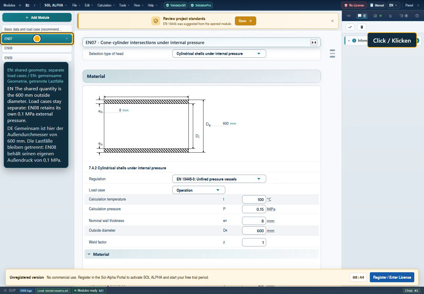
- Active construction
- Pressure, wall and diameter
Chapter 07Distinguishing units, thicknesses and diameters
Example pressures are expressed in MPa: 0.15 MPa equals 1.5 bar, and 0.1 MPa equals 1 bar. A result of 3.813383 MPa is therefore not 3.813383 bar. The unit is part of the value. When changing display units, check the converted number instead of reading the old number under a new unit. For stress, 1 MPa equals 1 N/mm².
Final wall thickness is 8 mm. The saved total allowance is 0.3 mm, leaving an analysis thickness of 7.7 mm. In SUIP, V24 is this available analysis thickness, V22 is required thickness without allowances, and V59 is required thickness including allowances. Compare analysis thickness with the requirement excluding allowances, or final thickness with the requirement including allowances. Mixing these comparisons can create an apparent reserve or deduct allowances twice.
The geometric inside diameter based on nominal dimensions would be 600 − 2·8 = 584 mm. The calculated analysis inside diameter in the teaching case is instead 600 − 2·7.7 = 584.6 mm. Mean analysis diameter is 592.3 mm. With 650 mm outside diameter, these become 634.6 and 642.3 mm. Here, the 0.6 mm difference follows from the two wall deductions and is not a rounding error.
Review deductions separately for each component. Shell, nozzle and reinforcing plate can need different values. Do not simply connect “V6 to V6”. A meaningful connection requires matching physical meaning, unit, geometric reference and load case, not matching field numbers.
Back to top ↑Chapter 08Understanding material selection and allowable stress
The approved case uses material entry 1232, displayed as 1.4571(P), X 6 CrNiMoTi 17-12-2, hot-worked plate, austenitic. The stored database description names older product-standard dates. The number 1232 is the example database identifier, not a universally applicable material number. In another database, select the appropriate product and delivery condition and check its full description.
The saved operating case contains a material strength of 440 MPa and an associated safety factor of 3, giving the allowable stress used here, 146.66667 MPa. This division explains the recorded values; it is not a general rule defining the governing strength value and factor for every material. The material dialog and selected calculation basis determine which data the calculation requires.
EN08 also needs elastic modulus. The starting case contains 194000 MPa at 100 °C. External-pressure assessment can respond to geometry and stiffness changes even when a strength value stays unchanged. Transferring only an allowable stress from EN07 therefore does not establish that EN08 has complete material data.
After changing temperature or material, open every affected material group and check updated properties and messages. A visible material name does not establish that all required data exist for the temperature, product form and thickness range. Document manually entered properties with their source and unit. Material selection, a directly entered strength value and a connected strength value have different provenance and should be distinguished in the review record.
Back to top ↑Chapter 09First pass: loading the prepared case
Download tutorial-vessel-a.sol, the starting file, and open it through the application's file/project function in your own practice project. It contains prepared EN07, EN08 and EN09 chapters; the shared diameter connection is established during the lesson. Save your own working copy before editing. Historical revision 2 is provided as a comparison artifact for the later end state.
After loading, check the constructions: EN07 cylindrical shell under internal pressure; EN08 unstiffened cylindrical shell under external pressure; EN09 single opening in a cylindrical shell without nozzle, viewed in an axial section. All three use operation, 100 °C and the material described above. The associated starting inputs appear below. Values are connected only where the workflow explicitly says so.
| Item | EN07 / SUIP | EN08 / SUEP | EN09 / NOIS |
|---|---|---|---|
| Load case | V1: Operation | V1: Operation | V1: Operation |
| Temperature | V3: 100 °C | V3: 100 °C | V3: 100 °C |
| Pressure | V4: 0.15 MPa | V4: 0.1 MPa | V4: 0.15 MPa |
| Material | V5: 1232 / 1.4571(P) | V5: 1232 / 1.4571(P) | V5: 1232 / 1.4571(P) |
| Outside diameter | V26: 600 mm | V246: 600 mm | V31: 600 mm |
| Final thickness | V16: 8 mm | V16: 8 mm | V50: 8 mm |
| Negative tolerance | V6: 0.3 mm | V6: 0.3 mm | V8: 0 mm |
| Forming allowance | V8: 0 mm | V8: 0 mm | V6: 0.3 mm |
| Corrosion allowance | V7: 0 mm | V7: 0 mm | V7: 0 mm |
| Additional specifications | V23: 1 | V43: 1000 mm; V31/V32: 150 mm | V34: 80 mm; V61: 100 mm |
| Construction | Cylinder | Unstiffened cylinder | Single, without nozzle, axial |
Wait for calculation to finish. Then read messages first, followed by the result groups. The unchanged starting case has the six values documented under Comparing results. In particular, check SUIP V15=584.6 mm and SUEP V96=7.7 mm as simple geometric consistency checks. A number in a result field alone is insufficient: the value must be known, calculated and appropriate to the current load case.
The starting file and recorded revision retain their original bytes. The numerical evidence comes from a demonstrably reopened starting archive and subsequent edits. A complete cold start including all implicit module defaults was not newly executed for this book. If you insert empty modules, also inspect material properties, basis selection and automatically established states; the compact input table does not replace the complete archive state.
Back to top ↑Chapter 10Connecting the shared diameter
The objective is a traceable geometry change with one deliberately chosen editing point. Outside diameter in the EN07 chapter is used as the shared value. The connection interface describes a bidirectional link; the editing direction chosen here is a practice rule for the example, not a claimed technical prohibition against editing another end.
- Open EN07 and the context menu of outside diameter SUIP V26=600 mm. Choose “Bookmark for linking”. Check the bookmarked field number and unit.
- Open EN08 and the context menu of outside diameter SUEP V246. Open the linking function and select the SUIP V26 bookmark. The dialog must identify SUEP V246 as target, SUIP V26 as source, and mm on both sides.
- Open EN09 and connect shell outside diameter NOIS V31 in the same way. Read its full description: this is shell diameter at the opening connection, not opening diameter.
- Inspect the two linked fields after completion. Both must still show 600 mm. Separately check SUEP V4=0.1 MPa. The geometry connection must not change that pressure.
The relationship is now stored in the application. A manually copied value could initially look identical but would not automatically follow later edits. An automatic child-module calculation is a different mechanism again; it is described separately under Constructions and children.
If the dialog shows a different unit or physical meaning, cancel that connection and select the correct field. In this lesson, connect neither the two pressure types nor the allowable pressures. EN08 external loading, EN07/EN09 internal loading and each allowable pressure play different roles. Matching units do not establish matching physical quantities.
600 → 650 mm
chosen editing point
External pressure V4 = 0.1 MPa
Internal pressure V4 = 0.15 MPa
Two explicit variable connections; bidirectional coupling, with editing at SUIP V26 in the lesson. Pressure and material fields are not automatically connected.
Watch the connected workflow
Historical video from 6 September 2026, English interface with bilingual captions. Only the video needs Internet access. Open video directly.
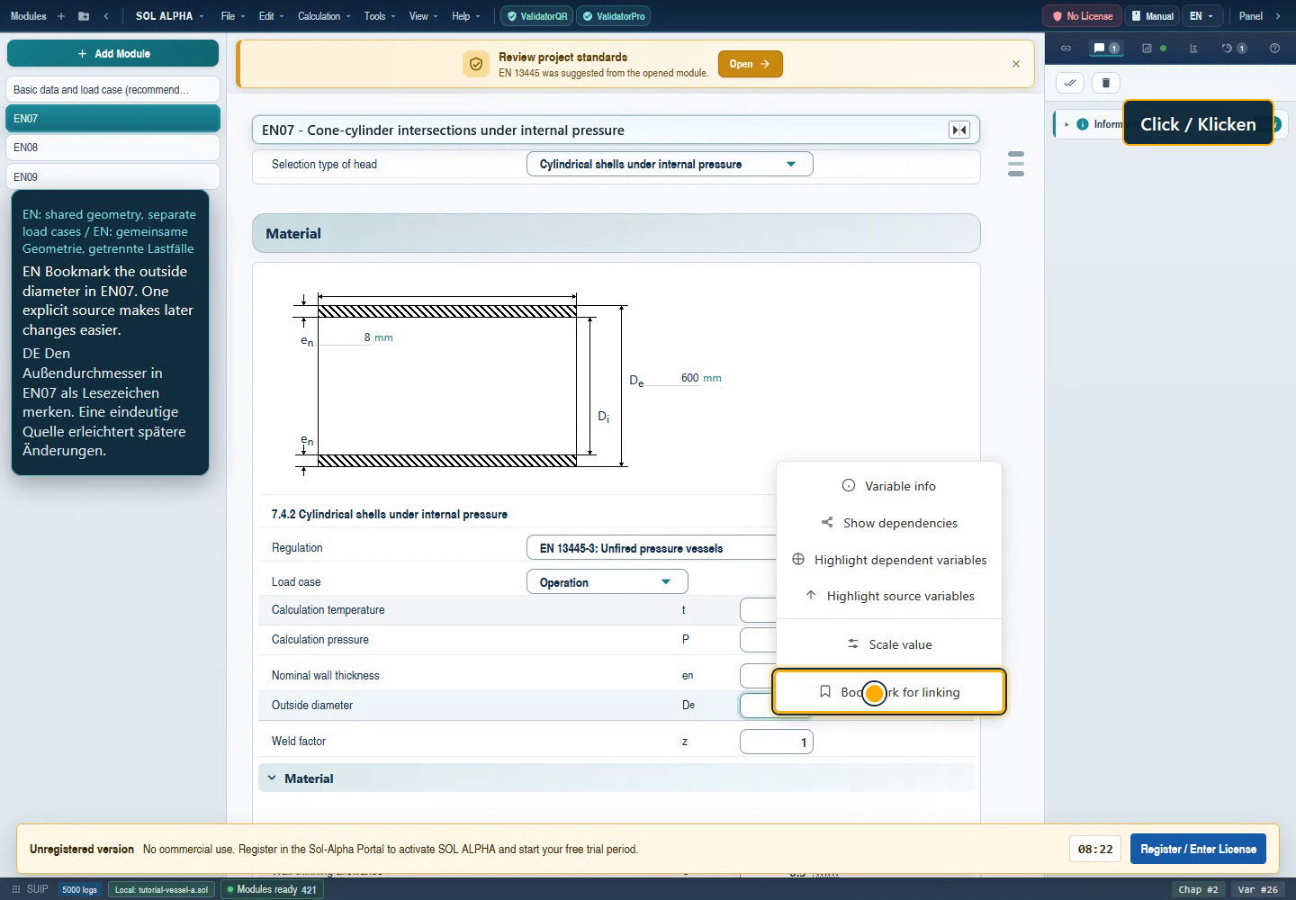
- Bookmark V26
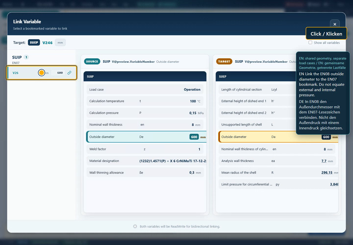
- Check target and unit
- Source SUIP V26
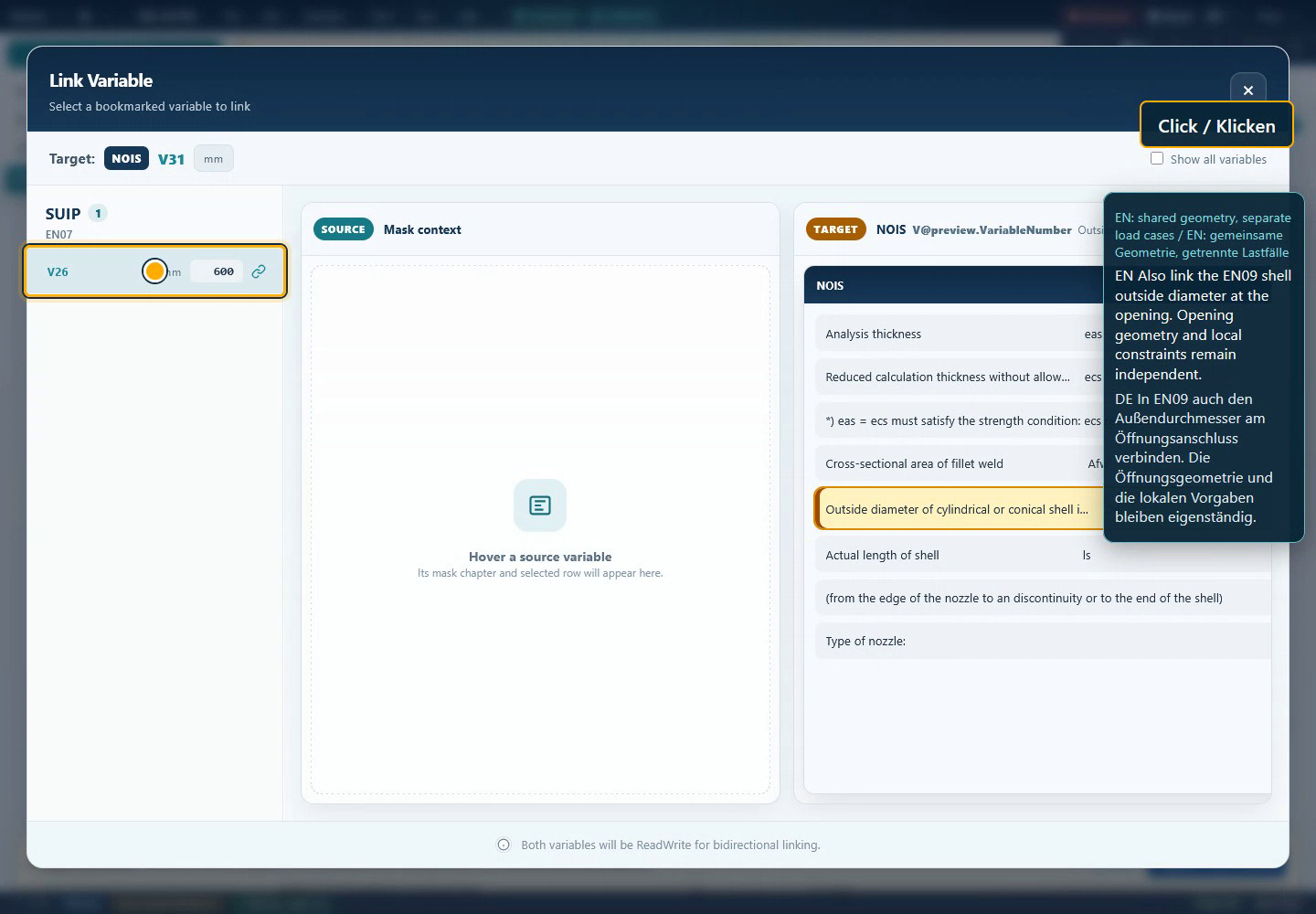
- Target NOIS V31
- The same source field
Chapter 11Revision case: changing 600 to 650 mm
You are investigating a larger vessel diameter while retaining thickness and loading. Change only SUIP V26 to 650 mm and confirm the entry. Wait until all participating chapters have recalculated. Then inspect SUEP V246 and NOIS V31; both must show 650 mm. If a field remains at 600 mm, resolve the connection first; a numerical method comparison is premature.
Check unchanged specifications: 8 mm wall thickness in every chapter, 0.15 MPa internal pressure in SUIP/NOIS, 0.1 MPa external pressure in SUEP, 100 °C and the respective allowance setup. Opening diameter stays 80 mm, and available shell length in NOIS stays 100 mm. A link does not scale an entire drawing; it transfers precisely the connected value.
Open each result group in turn. SUIP requires a slightly greater analysis thickness and reports lower allowable pressure. SUEP calculates lower allowable external pressure at unchanged analysis thickness. NOIS reports higher utilisation and lower maximum calculation pressure. The comparison table gives the exact magnitude; checking the direction alone would be insufficient.
Document this as a separate revision, with its reason, changed source field, retained conditions and reviewed results. For additional studies, change one deliberate parameter per variant. Changing material, thickness and pressure together makes causes difficult to distinguish. Larger geometry changes can also encounter applicability limits or require another construction; the successful 600→650 mm change does not establish arbitrary scalability.
Back to top ↑Chapter 12EN07 / SUIP: understanding the internal-pressure shell
For a cylinder, EN07 answers two related questions: what analysis thickness does the specified pressure require, and what pressure is allowable with the available analysis thickness? Keep these roles clear in operation: pressure V4 and final thickness V16 are starting specifications; V22 and V27 are calculated results. A small thickness requirement does not instruct you to reduce the selected fabrication thickness automatically.
Following the first shell assessment
- Select cylindrical shell, EN 13445-3 and operation. Check 100 °C and 0.15 MPa.
- Confirm 8 mm final thickness, 600 mm outside diameter and joint factor 1. That factor is an assumption of the lesson, not a general recommendation for every welded construction.
- Check material entry, operating strength, safety factor and the total allowance of 0.3 mm.
- Read 7.7 mm analysis thickness, 0.2990961 mm required thickness without allowances, approximately 0.5990961 mm with allowances and 3.813383 MPa maximum allowable pressure. Review strength and geometry conditions separately.
Understanding the numbers
The inspected cylinder branch derives allowable stress from the material strength and safety factor selected for the load case. It uses analysis inside diameter for thickness demand and mean analysis diameter for allowable-pressure evaluation. For this particular source branch, the relationships are:
Pmax = 2·f·z·eₐ / Dₘ
Here e is thickness demand without allowances, P is specified internal pressure, f is allowable stress, z is joint factor and eₐ is available analysis thickness. These equations explain the inspected program branch; they neither reproduce all code conditions nor authorise using them for other constructions. With Dᵢ=584.6 mm, f≈146.66667 MPa and z=1, they reproduce the documented thickness demand.
At 650 mm outside diameter, analysis inside diameter rises to 634.6 mm. Thickness demand rises to 0.32467738 mm, or approximately 0.62467738 mm including allowances. Allowable pressure falls to 3.5165293 MPa. This also explains why shared geometry changes affect reserves while pressure, material and final thickness remain unchanged.
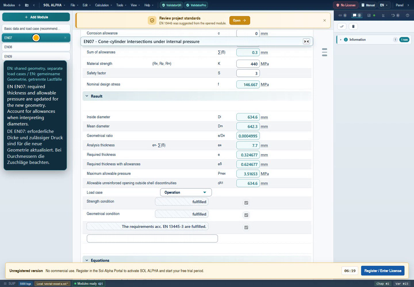
- Thicknesses and allowable pressure
- Read the conditions
Chapter 13EN08 / SUEP: external pressure and stability
External-pressure assessment is a separate task. Specified external overpressure is 0.1 MPa here. For the selected unstiffened cylindrical shell, EN08 evaluates geometric length, radius, analysis thickness and material behaviour among other factors. A high allowable internal pressure from EN07 does not establish stability of the shell under external pressure.
Entering geometry and boundary conditions
The prepared case contains V43=1000 mm cylindrical-section length and V31=V32=150 mm external head heights. These are not identical to the unsupported or effective shell length used in the results. The historical result image shows 1120 mm. Use the sketch and field help to understand the boundaries of each length. Overall vessel length must not be copied into every length field without checking its meaning.
Next inspect V246=600 mm outside diameter, V16=8 mm nominal wall and V96=7.7 mm analysis thickness. In the connected revision, V246 becomes 650 mm while thickness and lengths remain unchanged. Material properties and elastic modulus are needed for the specified temperature. No stiffener is modelled in this construction. If your vessel has stiffening rings, deliberately select and populate the appropriate method branch.
Reading the result group
The interface distinguishes circumferential-yield limit pressure, theoretical buckling pressure and allowable pressure, among other quantities. A value labelled “theoretical” is not automatically the final value suitable for comparison with loading. The inspected source branch determines V139 from its lower-bound pressure and associated safety factor. In the example, compare the specified 0.1 MPa with V139: initially 1.7043248 MPa, then 1.479529 MPa after the change.
V96 remains 7.7 mm. Its older source label “estimated shell thickness” is misleading: in this case the value follows directly from final thickness minus allowances. It is not a demonstrated minimum thickness for arbitrary external-pressure cases. Also read the shape-deviation conditions and messages. Out-of-roundness, changed support conditions or long unsupported sections can require another assessment route; the package map therefore includes UNRD, ENAF and stiffened SUEP constructions.
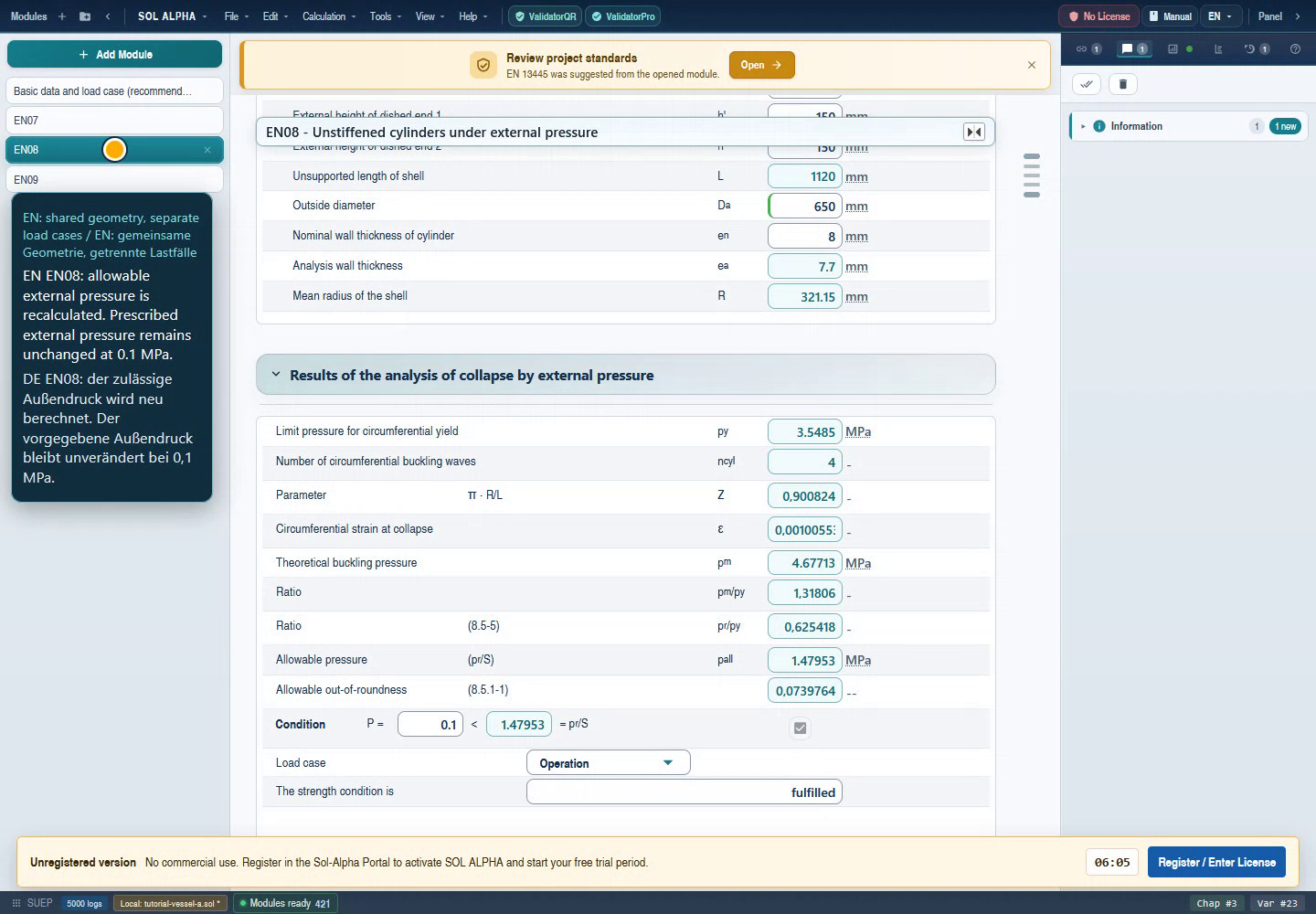
- Transferred geometry
- Allowable pressure
- Compare load with result
Chapter 14EN09 / NOIS: assessing the single opening
EN09 assesses how an opening affects local shell load capacity. The teaching case is deliberately simple: cylindrical shell, a single opening without nozzle, and an axial section. It contains no reinforcing plate, welded nozzle or neighbouring opening. This scope matters because additional components require their own geometry, materials and limited contributing cross-sections.
Setting up the opening case
Check V126=cylinder, V20=without nozzle and V86=axial. The shell has V31=600 mm outside diameter and V50=8 mm final thickness. Analysis thickness V51 is 7.7 mm. V34=80 mm supplies the opening geometry for this opening type; its generic source label is nozzle outside diameter. Read the active mask together with the selection instead of inferring a physical nozzle from a generic label.
V61=100 mm defines the shell length available to contribute. This is not an arbitrary reserve that can be made generously large. It must reflect the actual distance from the opening to relevant boundaries. The application distinguishes available, maximum credited and effectively used lengths. The historical end-state image limits effective length to approximately 70.3257 mm. Additional available material is therefore not always credited in full.
Reading utilisation and pressure reserve
NOIS V75 is the maximum calculation pressure for the opening case being assessed. V85 is its utilisation. The inspected equation evaluates V85=V4/V75. Thus 0.15/2.3833601≈0.06293636 initially corresponds to about 6.29%, and 0.15/2.2318661≈0.067208335 after the change corresponds to about 6.72%. The result field itself is dimensionless; do not enter the percentage 6.72 in place of the ratio 0.0672.
Low utilisation in this section does not automatically complete every opening assessment. Review geometry conditions, governing sections, proximity of other openings and additional connection loads. Package modules E164/E165 and NOLS/NOLO concern other local-load tasks; favourable NOIS pressure utilisation does not replace them.
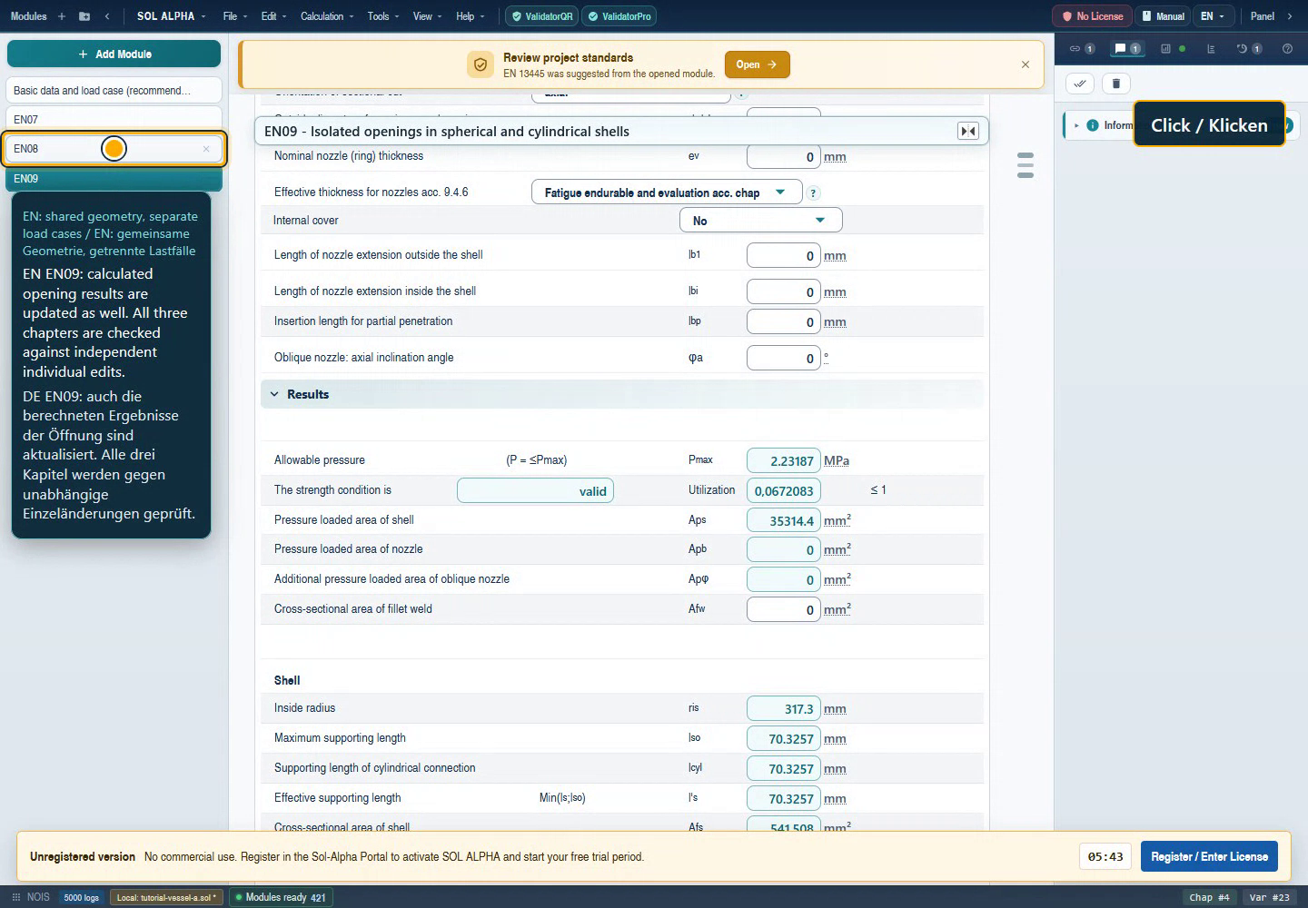
- Utilisation and pressure
- Effective lengths
Chapter 15Checking six results together
The table contains historical measurements before and after the geometry change. The published video check compared linked chapters with separately edited reference chapters in the same calculation environment. Absolute comparison tolerance for the six target values was 0.0001 in the stated unit. This establishes the recorded revision workflow, not independent Desktop parity or comprehensive code verification.
| Module / field | Meaning | 600 mm | 650 mm | Unit |
|---|---|---|---|---|
| EN07:V22 | Required thickness without allowances | 0.2990961 | 0.32467738 | mm |
| EN07:V27 | Maximum allowable internal pressure | 3.813383 | 3.5165293 | MPa |
| EN08:V139 | Allowable external pressure | 1.7043248 | 1.479529 | MPa |
| EN08:V96 | Available analysis thickness | 7.7 | 7.7 | mm |
| EN09:V85 | Opening-case utilisation | 0.06293636 | 0.067208335 | — |
| EN09:V75 | Maximum opening calculation pressure | 2.3833601 | 2.2318661 | MPa |
Read unchanged analysis thickness as a control quantity: a diameter connection does not alter allowances or nominal wall thickness. The other five results respond to the larger geometry. Allowable pressures decrease; thickness demand and opening utilisation increase. A useful comparison therefore includes both responding results and quantities deliberately expected to stay unchanged.
Compare allowable pressures only within the appropriate load case. SUIP and NOIS may be compared here within the simplified internal-pressure lesson: the opening case has the lower of those two allowable pressures. SUEP concerns the opposite pressure direction and must not be inserted into the same minimum calculation as an equivalent internal-pressure limit. A project-level evaluation requires a complete component and load-case assignment.
If your display differs slightly, first check unit, rounding, construction, material properties and saved allowances. The reference numbers retain more digits than a typical report to make comparisons traceable; digit count does not imply corresponding physical accuracy. For larger deviations, preserve the starting file, program information and messages before changing assumptions. Do not adjust safety factors or material properties merely to match the reference value.
Back to top ↑Chapter 16Inverse calculation with controlled degrees of freedom
Reading the mask from top to bottom is a recommendation for understandable work. The equation system can evaluate selected relationships in another direction. What matters is which quantities are specified, free, calculated or connected. Simply overwriting a calculated result while retaining all previous fixed specifications can create a contradictory or overdetermined state.
A traceable inverse question for the simple SUIP cylinder is: what pressure just uses the available analysis thickness? In the unchanged 600 mm case, eₐ=7.7 mm is known. Rearranging this source branch's thickness relationship gives P=2·f·z·e/(Dᵢ+e). With e=7.7 mm, Dᵢ=584.6 mm, f≈146.66667 MPa and z=1, the result is approximately 3.813383 MPa. This agrees with the separately recorded allowable-pressure evaluation.
This numerical cross-check is a source and arithmetic check, not a freshly executed inverse operating workflow. For your own exercise, save a new, initially unlinked variant. Specify the desired thickness demand V22 and release previous pressure V4 as the unknown. Keep material, allowable stress, joint factor and geometry consistent. After each state change, inspect whether the solver supports the intended direction and which conditions still apply.
Target seeking through repeated trials is another approach: for example, vary nominal wall thickness while observing a target utilisation. Distinguish a temporary search from a persistent exchange of input/result roles in the report. EN08 includes nonlinear stability conditions and potentially discrete wave numbers; NOIS can limit effective lengths. Neither therefore guarantees arbitrary smooth or unique inverse solutions.
Finally, restore the original specification roles or clearly identify the inverse variant. In particular, do not prescribe the allowable pressure as one shared load across all three chapters: this inverse relationship concerns only the described SUIP cylinder and its current boundary conditions.
Back to top ↑Chapter 17Other constructions and automatic subcalculations
SUIP also contains spherical shells, torispherical and basket-arch heads, elliptical heads, cones and cone-cylinder junctions. Head branches treat membrane, knuckle and buckling conditions as well as geometry limits separately. Cones and junctions add angles, radii, reinforced wall regions and influence lengths. The cylinder example's fields are therefore not a complete input list for these constructions.
One concrete source finding concerns the external-pressure branch of certain dished heads: through its process-macro route, SUIP creates a SUEP subcalculation for the crown, populates associated values and reads back an allowable pressure. This conditional automatic subcalculation is different from the manual connection of three separately inserted chapters used in our lesson. It is documented here as a source route; its complete current Web operation was not separately executed.
SUEP offers unstiffened, lightly and heavily stiffened cylinders, cones, cone-cylinder junctions and spherical shells. Stiffener profiles, spacing, moments of inertia and boundary conditions need their own input evidence. A ring in a sketch does not establish its effectiveness. For shape deviations, add the appropriate geometry and tolerance assessments to the assessment plan.
NOIS distinguishes single and multiple openings as well as several shell and connection constructions. Nozzles and reinforcement need their own material, wall, lengths and permitted contribution; neighbouring openings additionally need spacing and position. A single-opening calculation cannot simply be duplicated if contributing regions overlap. Begin such tasks in their own variant and inspect available constructions and messages before assembling the results.
Back to top ↑Chapter 18Extending the assessment plan
After the core lesson, first add the vessel components that remain unassessed. Appropriate SUIP constructions cover dished heads, EN10 or FLEN cover flat ends, and EFL covers flanges. Select by construction, loading and method version. An identifier alone is insufficient, especially when several entries concern the same topic.
Additional piping or connection loads require local-load modules. Define forces and moments with reference point and direction before transferring values. For supports, choose saddles, legs, brackets, rings or skirts to match installation. Wind and global loads must be consistent with those support assumptions. A favourable pressure assessment cannot compensate for a missing structural load case.
Heat exchangers add tubesheets and thermally driven boundary conditions. WTS – Heat exchanger calculation explains the thermal task. E134/E135/E136 and other tubesheet routes address mechanical tasks. A temperature from WTS is initially an engineering handoff; this handbook does not claim an automatically established connection between the books or modules. Explicitly check operating temperature, metal temperature and load-case reference.
AD 2000 and ASME provide alternative or project-dependent code routes. Geometrically similar tasks can use different input definitions and assessments. Do not transfer allowable stress or utilisation from one code to another without checking the basis. For method comparisons, keep geometry, material basis, allowances and load cases traceable and distinct.
Back to top ↑Chapter 19Saving, reopening and reporting
Save the unchanged starting case and each intentional change under traceable names. A useful revision note is: “Outside diameter 600→650 mm in SUIP V26; linked to SUEP V246 and NOIS V31; pressure cases and thicknesses unchanged.” Add date, author and review status according to your project process. The historical video end state was saved separately; no new complete end-state roundtrip was executed during this handbook work.
Perform a reopen check in your own practice project: save, open another empty project, then reload the saved variant. Check constructions, load cases, material description, allowances, units and both connections, rather than only three numbers. In another copy, change shared diameter back to 600 mm. The intended targets should follow while EN08 retains 0.1 MPa external pressure.
A report needs inputs alongside results. For each chapter, identify values directly specified, obtained from material data or transferred from another chapter. Retain the six comparison values with units and messages. Document active construction and agreed basis; as the historical EN07 example shows, a printed heading alone can be incomplete.
Use the handbook's print function if you need a working guide. Print layout reveals content hidden by search so chapters are not silently omitted. For a calculation report, use the application's project output and review its actual scope. A handbook printout is guidance, not a record of your particular calculation state.
Back to top ↑Chapter 20Troubleshooting: 20 common situations
I cannot find EN07 under SUIP.
EN07 and SUIP are the display and execution names of the reviewed entry. Search module selection for EN07 and connection/state information for SUIP. In another installation, also check package filters and availability.
The heading names a cone-cylinder junction but the sketch shows a cylinder.
In the historical EN07 capture, the general heading does not track the selected construction. Check selector, geometry and populated fields together. This lesson uses a cylindrical shell under internal pressure.
EN08 does not take the new diameter.
Check target SUEP V246 and source SUIP V26. A stored number 600 alone is not a connection. Inspect link state and wait for recalculation to complete.
EN08 has the wrong pressure after linking.
The lesson connects diameter only. Check whether pressure fields were linked accidentally. EN08 V4 must remain 0.1 MPa here; internal pressure in SUIP/NOIS is 0.15 MPa.
Why is inside diameter 584.6 rather than 584 mm?
The result uses 7.7 mm analysis thickness after allowances. Thus 600−2·7.7=584.6 mm. A value of 584 mm uses nominal wall 8 mm and a different geometric reference.
Is the SUIP requirement of 0.299 mm already the ordered thickness?
No. V22 is analysis demand without allowances here; V59 adds them. Fabrication, stability, handling and other applicable conditions require separate review. The example retains final thickness 8 mm.
Why does SUEP V96 stay at 7.7 mm?
In this case V96 equals final thickness minus allowances. Only outside diameter changes. Allowable external pressure responds while analysis thickness stays unchanged.
May I use theoretical buckling pressure as allowable pressure?
Read final evaluation V139 and its condition against specified external pressure. The mask shows several intermediate and limiting pressures. Their names are not interchangeable descriptions of one assessment value.
Why is unsupported length greater than 1000 mm?
1000 mm is the example cylindrical-section length. End geometry contributes to effective length; the historical image shows 1120 mm. Check dimension definitions before treating a result length as an incorrect input.
NOIS V85 is named Joint Efficiency in English.
The reviewed equation forms calculation pressure divided by maximum pressure. It means utilisation here, displayed as Utilization in the result image. The weld joint factor is a different quantity.
Should I read utilisation as 6.72 or 0.0672?
The field contains a dimensionless ratio: about 0.0672 equals about 6.72%. Check unit and presentation. A factor of 100 is not a small rounding effect.
Why does more available shell length produce little improvement?
NOIS limits credited length. Compare available, maximum and effective lengths. Beyond the effective limit, additional geometry does not automatically contribute to load-carrying area.
Can V6 be connected across all three modules?
No. SUIP/SUEP V6 means negative tolerance, while NOIS V6 means forming allowance. NOIS negative tolerance is V8. Connect by physical meaning, not matching numbers.
A material name exists but results are missing.
Check whether required properties exist for temperature, product form and thickness. Open the material group and read messages. A name alone establishes neither complete data nor completed calculation.
The reference no longer matches after changing material.
The reference belongs to stored entry 1232 and the documented properties. Another database or temperature may provide different values. Document the change instead of treating it as the same reference case.
I want to prescribe a result but calculation becomes inconsistent.
Inspect existing fixed states and links. Release an appropriate previous specification and start in an unlinked copy. Conditional equations and discrete selections do not support arbitrary inversion.
All three chapters say fulfilled. Is the vessel complete?
Each chapter covers its own task only. Review heads, flanges, supports, additional loads, other openings, cycles and all other agreed conditions. The lesson does not contain a complete real vessel.
The saved project reopens with different values.
Compare constructions, code selection, material state, units, specification roles and connections. Preserve both files and program information. Another software version may require its own documented comparison.
The package has several modules for one topic.
Identifiers such as EN17/E17N/EK17 or EN10/FLEN are not automatically aliases. The package map records their reviewed roles. Choose the appropriate execution/method version rather than the shortest name.
The video is unavailable offline.
Use the complete local instructions with original images and comparison values. Only the externally hosted video needs Internet access. Starting/revision files and both languages are included in the handbook folder.
Chapter 21Glossary and review protocol
| Term | Meaning in this handbook |
|---|---|
| Final thickness | Available or selected nominal wall, 8 mm in the example. |
| Analysis thickness | Thickness used in calculation after applicable deductions, 7.7 mm here. |
| Required thickness | Calculated demand; check whether the field includes allowances. |
| External pressure | External overpressure in a separately defined loading case. |
| Utilisation | Ratio of loading to corresponding capacity; NOIS V85 is P/Pmax here. |
| Effective length | Length actually credited by the method, potentially smaller than available length. |
| Specification | Deliberately set value; known does not automatically mean permanently fixed. |
| Connection | Stored relationship between specific variables, not simply matching numbers. |
| Child module | Subcalculation generated or called automatically by a parent module. |
| Historical evidence | An actually recorded earlier state with date and provenance; not a new run. |
Review before handing over
- Task: Are components, loads, conditions and exceptions fully identified?
- Basis: Are agreed edition, selected method and documented program version consistent?
- Data: Are dimensions, material conditions, units and allowances traceable and consistent?
- Connections: Do source and target mean the same thing, and does the transfer visibly occur after a change?
- Results: Has calculation finished, have conditions been read, and are governing results documented with units?
- Archive: Can the saved revision be reopened with the same assumptions and connections?
A useful next exercise changes just one item: a larger opening, another external pressure or a different unsupported shell length. State the expected reaction first, then compare it with the actual response. Reinforced/adjacent openings and stiffened external-pressure shells need additional example evidence appropriate to those constructions.
Back to top ↑Chapter 22EN07 / EN08 / EN09 field reference
90 selected operating and result fields. Starting values refer to the historical starting archive. Conditional, unknown and inactive fields receive no invented example values. Translations are editorially reviewed; misleading source labels are explained in the text.
SUIP
| Variable | Meaning | Starting value | Unit / state |
|---|---|---|---|
| SUIP:V1 | Load case | Operation | — · known |
| SUIP:V3 | Calculation temperature | 100 | °C · known |
| SUIP:V4 | Internal pressure | 0.15 | MPa · known |
| SUIP:V5 | Material selection | (1232) 1.4571(P) = X 6 CrNiMoTi 17-12-2: EN 10028-7:2008-02;AD W 2:2008-02;Hot worked plate;Austenite | — · known |
| SUIP:V6 | Negative tolerance | 0.3 | mm · known |
| SUIP:V7 | Corrosion allowance | 0 | mm · known |
| SUIP:V8 | Forming allowance | 0 | mm · known |
| SUIP:V9 | Total allowance | 0.3 | mm · calculated |
| SUIP:V14 | Allowable stress | 146.66667 | MPa · calculated |
| SUIP:V15 | Analysis inside diameter | 584.6 | mm · calculated |
| SUIP:V16 | Final wall thickness | 8 | mm · known |
| SUIP:V17 | Strength value, testing | 520 | MPa · known |
| SUIP:V18 | Safety factor, testing | 2 | — · known |
| SUIP:V19 | Strength value, operation | 440 | MPa · known |
| SUIP:V20 | Safety factor, operation | 3 | — · known |
| SUIP:V22 | Required thickness without allowances | 0.2990961 | mm · calculated |
| SUIP:V23 | Weld joint factor | 1 | — · known |
| SUIP:V24 | Available analysis thickness | 7.7 | mm · calculated |
| SUIP:V25 | Mean analysis diameter | 592.3 | mm · calculated |
| SUIP:V26 | Outside diameter; shared geometry | 600 | mm · known |
| SUIP:V27 | Maximum allowable pressure | 3.813383 | MPa · calculated |
| SUIP:V28 | Geometry ratio | 0.0004984935 | — · calculated |
| SUIP:V32 | Inside knuckle radius; head | — | conditional / not populated |
| SUIP:V33 | Inside crown radius; head | — | conditional / not populated |
| SUIP:V42 | Head thickness for membrane stress | — | conditional / not populated |
| SUIP:V43 | Knuckle thickness against yielding | — | conditional / not populated |
| SUIP:V44 | Knuckle thickness against plastic buckling | — | conditional / not populated |
| SUIP:V59 | Required thickness with allowances | 0.5990961 | mm · calculated |
| SUIP:V72 | Cone half-angle | — | conditional / not populated |
| SUIP:V141 | Allowable unreinforced opening outside discontinuities | 584.6 | mm · calculated |
SUEP
| Variable | Meaning | Starting value | Unit / state |
|---|---|---|---|
| SUEP:V1 | Load case | Operation | — · known |
| SUEP:V3 | Calculation temperature | 100 | °C · known |
| SUEP:V4 | External overpressure; remains independent | 0.1 | MPa · known |
| SUEP:V5 | Shell material | (1232) 1.4571(P) = X 6 CrNiMoTi 17-12-2: EN 10028-7:2008-02;AD W 2:2008-02;Hot worked plate;Austenite | — · known |
| SUEP:V6 | Negative tolerance | 0.3 | mm · known |
| SUEP:V7 | Corrosion allowance | 0 | mm · known |
| SUEP:V8 | Forming allowance | 0 | mm · known |
| SUEP:V9 | Total allowance | 0.3 | mm · calculated |
| SUEP:V10 | Shell material strength | 440 | N/mm² · calculated |
| SUEP:V16 | Nominal wall thickness | 8 | mm · known |
| SUEP:V31 | External head height 1 | 150 | mm · known |
| SUEP:V32 | External head height 2 | 150 | mm · known |
| SUEP:V39 | Safety factor for limit pressure | 1.5 | — · calculated |
| SUEP:V41 | Unsupported shell length | 1120 | mm · calculated |
| SUEP:V43 | Cylindrical-section length | 1000 | mm · known |
| SUEP:V46 | Stiffener spacing; conditional | — | conditional / not populated |
| SUEP:V61 | Circumferential buckling-wave count | 4 | — · calculated |
| SUEP:V62 | Theoretical instability pressure | — | conditional / not populated |
| SUEP:V65 | Lower-bound pressure | 2.5564873 | MPa · calculated |
| SUEP:V66 | Circumferential-yield limit pressure | 3.8480499 | MPa · calculated |
| SUEP:V68 | Mean shell radius | 296.15 | mm · calculated |
| SUEP:V74 | Shell 0.2% proof strength | 185 | N/mm² · known |
| SUEP:V96 | Analysis thickness: nominal wall minus allowances | 7.7 | mm · calculated |
| SUEP:V97 | Shell elastic modulus | 194000 | MPa · known |
| SUEP:V98 | Poisson ratio | 0.3 | — · known |
| SUEP:V112 | Stiffener material; conditional | — | conditional / not populated |
| SUEP:V117 | Stiffener elastic modulus; conditional | — | conditional / not populated |
| SUEP:V126 | Austenitic material; state indicator | Yes | — · known |
| SUEP:V139 | Allowable external pressure | 1.7043248 | MPa · calculated |
| SUEP:V246 | Outside diameter; connection target | 600 | mm · known |
NOIS
| Variable | Meaning | Starting value | Unit / state |
|---|---|---|---|
| NOIS:V1 | Load case | Operation | — · known |
| NOIS:V3 | Calculation temperature | 100 | °C · known |
| NOIS:V4 | Calculation pressure | 0.15 | MPa · known |
| NOIS:V5 | Shell material | (1232) 1.4571(P) = X 6 CrNiMoTi 17-12-2: EN 10028-7:2008-02;AD W 2:2008-02;Hot worked plate;Austenite | — · known |
| NOIS:V6 | Shell forming allowance | 0.3 | mm · known |
| NOIS:V7 | Shell corrosion allowance | 0 | mm · known |
| NOIS:V8 | Shell negative tolerance | 0 | mm · known |
| NOIS:V9 | Total shell allowance | 0.3 | mm · calculated |
| NOIS:V20 | Opening/nozzle type | WithoutNozzle | — · known |
| NOIS:V30 | Shell allowable stress | 146.66667 | MPa · calculated |
| NOIS:V31 | Shell outside diameter at connection | 600 | mm · known |
| NOIS:V32 | Shell analysis inside diameter | 584.6 | mm · calculated |
| NOIS:V34 | Opening/nozzle outside diameter, depending on type | 80 | mm · known |
| NOIS:V35 | Nozzle inside diameter; conditional | 0 | mm · calculated |
| NOIS:V40 | Required shell analysis thickness at connection | 7.7 | mm · calculated |
| NOIS:V44 | Actual nozzle thickness; conditional | 0 | mm · known |
| NOIS:V46 | Reinforcing-plate nominal thickness; conditional | 0 | mm · known |
| NOIS:V50 | Final shell thickness | 8 | mm · known |
| NOIS:V51 | Shell analysis thickness | 7.7 | mm · calculated |
| NOIS:V54 | Outside nozzle length; conditional | 0 | mm · known |
| NOIS:V55 | Inside nozzle length; conditional | 0 | mm · known |
| NOIS:V61 | Available shell length | 100 | mm · known |
| NOIS:V62 | Effective shell length | 67.53303 | mm · calculated |
| NOIS:V65 | Maximum credited shell length | 67.53303 | mm · calculated |
| NOIS:V71 | Load-carrying shell cross-section | 520.0043 | mm² · calculated |
| NOIS:V73 | Pressure-loaded shell area | 31739.902 | mm² · calculated |
| NOIS:V75 | Maximum calculation pressure | 2.3833601 | MPa · calculated |
| NOIS:V85 | Utilisation P/Pmax; not a weld factor | 0.06293636 | — · calculated |
| NOIS:V86 | Assessment section | Axial | — · known |
| NOIS:V126 | Shell type | Cylinder | — · known |
Chapter 23Sources, age and limits of the evidence
The technical basis was assembled on 7 September 2026 from the Web repository (main13.0, 1cd12e8b173ba72aa5c95c98a14772b7ee537997) and module sources in All-Dev (fix-iteration/v10, 40606b705b2df95e550ffef5e98ab733ccc66229). The source snapshot with file hashes and historical runtime evidence are separate. Source commits are not presented as proven versions of the recorded plugin binaries; their precise revision was not independently identified.
Source review covers package configuration, XML descriptions, the EN07/SUIP, EN08/SUEP and EN09/NOIS aliases, all ten associated mask files and selected calculation/material/child-module branches. The field reference contains 90 deliberately selected fields. This does not fully document internal helper fields, every special menu or every equation in every package member. The package map provides orientation for other modules, without inventing individual manuals.
Numerical evidence comes from the approved “EN: shared geometry, separate load cases” tutorial recorded on 6 September 2026. The starting case was opened, two diameter links established, and six target values after 600→650 mm compared with separate individual edits in the same environment. Unchanged external pressure was also checked. Files are pinned by SHA-256. The name “independent-recalculation-reference” refers to separate operating edits here, not independently developed calculation software.
The seven images are unaltered frames from that video. Image provenance records video hash, time and image hash. Old video captions, incomplete preview labels and licence notices remain visible. Numbered highlights are separate HTML elements. Every original image can be opened directly.
Not newly executed for this edition: cold start of all three modules, inverse operating sequence, complete renewed end-state roundtrip, stiffened external-pressure cases, reinforced/adjacent openings, every other construction and Desktop/Web parity. Algebraic inversion is explicitly labelled a source check. Documentation verification checks the book's structure, language alignment and usability; it does not certify a calculation engine.
Back to top ↑