EN 13480 – Piping calculations
Understand pipe wall, ends, branches, external pressure and attachments through traceable source calculations and a clear data plan.
No chapter found. Try another search term.
Chapter 01From a pipe component to a traceable piping assessment
This handbook explains how to divide a piping task into suitable calculation steps. It starts with a straight pipe under internal pressure. A dished closure, a branch, a separate external-pressure case and an integral attachment add different questions. You learn which data are shared, which results belong together, and where additional load and geometry data are needed.
The package map covers all eight configured entries. ER06/ER64, ER07, ER08, ER09 and ER11 form the main learning route. WA10, WA11 and WA07/WA7 are included in the same selection package but identify EN 12952-3 as their basis. Inclusion in the list does not make them EN 13480 methods. Selection and result transfer explicitly preserve that distinction.
First follow the straight-pipe case, then the pressure change and switch of governing load case. Values are independently recalculated from the inspected ER64 source relationships and compared with existing test expectations. This is a traceable calculation guide, not a newly recorded solver execution. The additional 200 mm hemispherical-end case is an explicitly constructed analytical exercise sharing the geometry.
Use the module chapters, field reference and troubleshooting guide in everyday work. Local program icons illustrate module tasks; they are not screenshots of an executed calculation. A newly executed connected overall case and its captures remain a separate runtime verification task.
Back to top ↑Chapter 02Describing piping as a system
Piping involves more than a pipe diameter. It contains components, connection points, supports, end conditions and several loading states. Pressure may determine wall thickness while weight, connected equipment or restrained thermal expansion introduce other stresses. Even with adequate wall thickness, an attachment or another load state may require additional assessment.
Begin with a sketch and component list. Identify straight sections, bends, branches, reducers, closures and connections. Assign stable labels, such as R1 for the straight section and E1 for the end. Include geometric discontinuities, material changes and joints. These labels later associate inputs and results with an actual location.
Prepare a separate load-case list. Operation, pressure testing, possible external pressure, erection and special temporary conditions must not merely be additional pressure numbers in one row. Assign temperature, material data, forces and applicable moments to each condition. Cyclic loading additionally requires its loading history.
The eight configured package modules do not guarantee coverage of every task in a real line. In particular, component pressure assessment does not replace a complete flexibility or piping-system analysis. Obtain support and connection loads from an appropriate system model and document their origin. A complete task list establishes which additional methods are required.
Back to top ↑Chapter 03All eight package members at a glance
This map follows actual configured package membership. It identifies every token and every explicitly configured main variant. Selection name, internal module identifier and code-related engineering task remain distinct. Detailed chapters cover the connected ER tasks and the limits of the WA grouping.
| Selection / identifier | Task and variants | Identified in source | Learning route |
|---|---|---|---|
ER06 / ER64 | Straight pipes, pipe bends, segment bends, reducers, conical shells and various joints
| DIN EN 13480-3/6: 2024-12 | Open chapter |
| ER07 | Hemispherical, dished and flat ends (welded, bolted, with openings)
| DIN EN 13480-3/7: 2024-12 | Open chapter |
| ER08 | T-pieces for single and multiple openings. Branch with ribs
| DIN EN 13480-3/8: 2024-12 | Open chapter |
| ER09 | Cylindrical pipes, pipe bends, reducers and dished ends under external pressure.
| DIN EN 13480-3/9: 2024-12 | Open chapter |
| ER11 | Calculation of supporting and guide trunnions
| DIN EN 13480-3/11: 2024-12 | Open chapter |
| WA10 | This section applies to the design and dimensioning of spherical shells and dished heads, if necessary with openings.It does not deal with the influence of external forces and moments. If necessary, these must also be taken into account. | DIN EN 12952-3: 2023-01 | Open chapter |
| WA11 | The module determines the required wall thickness of pipes and pipe bends, | DIN EN 12952-3: 2023-01 | Open chapter |
WA07 / WA7 | The module determines the required wall thickness of jackets of drums and collectors under internal pressure. This requires the specification of the boundary conditions, the geometric sizes and the loads on the component. | DIN EN 12952-3: 2023-01 | Open chapter Source and package membership present; standalone Web registration absent from both inspected registries. |
Original selection icon for this module group; not an image of the straight 200 mm teaching pipe.

Original hemisphere-variant symbol; not a calculated screen view.
Original rib-reinforcement symbol. Such reinforcement is not specified by the learning data sheet.

Original head-variant symbol; the pipe external-pressure task uses another selection.

Original program symbol; actual geometry and loads are project-specific.
Unaltered originals from the published module symbols. Provenance and SHA-256.
Back to top ↑Chapter 04Code, edition and module identifier
DIN EN 13480-3:2024-12 addresses design and calculation of metallic industrial piping; the official DIN Media publication identifies the German version EN 13480-3:2024 and predecessor editions. The NEN entry for the 2024 edition provides the corresponding European reference. Complete restricted standards are not reproduced here.
Inspected catalogue sources for ER64, ER07, ER08, ER09 and ER11 name 2024-12 and sections 6, 7, 8, 9 and 11 respectively. An existing older test specification can nevertheless originate from another engine revision. Keep project requirements, catalogue description, inspected source and actually loaded module version distinct. A new catalogue line is not a documented rerun of every archived file.
ER64 is displayed as ER06 in selection. Both names refer to the same reviewed catalogue entry here. The internal identifier remains important for field references. WA7 is displayed as WA07 but is absent from both currently inventoried Web registration lists; no universally available Web start route is promised. WA10/WA11/WA7 name EN 12952-3:2023-01 and are treated as separate code routes.
Establish the agreed project edition before starting. Then check construction, material specifications and method options in the chapter actually opened. Document changes to an archived calculation's basis as a revision. Matching dimensions and similar result names do not make different codes interchangeable.
Back to top ↑Chapter 05Units, material data and specification roles
Record every quantity with its unit, meaning and origin. The lesson uses mm for dimensions and MPa for pressure and stress. ER64 additionally has explicit pressure fields in bar: V61 is operating pressure in bar and V4 is the same operating pressure in MPa; V62 is test pressure in bar and V21 is the same test pressure in MPa. These are linked representations within one module, not independent loads.
The source branch explicitly handles pressure-specification choice. When one representation is populated, it can release the other's prior known/fixed state. Do not therefore specify inconsistent values such as V61=1 bar and V4=1 MPa at the same time. Check conversion after entry: 1 bar=0.1 MPa and 2 bar=0.2 MPa. A similar field number in ER09 has another meaning.
The archived ER64 test specifies operating strength 218 MPa with factor 1.5 and test strength 260 MPa with factor 1.05. These give allowable stresses of approximately 145.333333 and 247.619048 MPa. They are retained as fixed teaching assumptions. The stored material description alone is not treated as proof that a current database derives these values. Actual work requires checking product form, temperature, thickness range and delivery condition.
“Known”, “fixed”, “calculated” and “connected” describe different states. Initially work through the mask from top to bottom and use variable information or its context menu to inspect the current role. Available test files contain inputs and expectations, not complete current UI locking state. Do not infer an allegedly locked control merely from a JSON input.
Back to top ↑Chapter 06First calculation: straight pipe ER06 / ER64
Open ER06 and select “Straight pipes and pipe bends”, then straight pipe. Its internal identifier is ER64. The lesson uses outside diameter 200 mm, final wall 5 mm, 120 °C, operating pressure 1 bar and test pressure 2 bar. Negative tolerance is 0.3 mm; corrosion and manufacturing allowances are zero. Joint factor is 1. The complete readable data specification is local; it is not a SOL project file.
| ER64 field | Item | Starting value | Reference |
|---|---|---|---|
| V130 / V35 | Main selection / construction | 1 / 1 | Straight pipe |
| V26 | Outside diameter | 200 mm | Specified outside dimension |
| V16 | Final wall | 5 mm | Nominal wall |
| V6 / V7 / V8 | Negative tolerance / corrosion / forming | 0.3 / 0 / 0 mm | Separate allowances |
| V3 | Temperature | 120 °C | Operating specification |
| V19 / V20 | Operating strength / factor | 218 MPa / 1.5 | Specified teaching data |
| V17 / V18 | Test strength / factor | 260 MPa / 1.05 | Separate test basis |
| V23 | Weld factor | 1 | Operation in source branch |
| V61 / V4 | Operating pressure | 1 bar / 0.1 MPa | One physical pressure |
| V62 / V21 | Test pressure | 2 bar / 0.2 MPa | Separate load case |
| V39 | Time-dependent stress | N | Archived selection |
These values come from the existing ER64 straight-pipe test specification. Its expected values are explicitly identified below as archived test expectations. The documentation work did not newly execute this dataset with the module solver. When entering it yourself, also inspect material/selection states and calculation completion. “expectSuccess” in a test file is the test's expectation, not the outcome of a run executed today.
First check simple geometry: 5−0.3=4.7 mm available analysis thickness. This source branch derives analysis inside diameter 200−2·4.7=190.6 mm. Nominal inside diameter using 5 mm wall would be 190 mm. Both numbers have different, traceable references. Retain outside diameter as the specification and allow the derived inside diameter to calculate.
Then read operation, testing, governing demand without allowances and demand including allowances separately. In the starting case, testing requires slightly more thickness than operation. Final wall stays 5 mm; the module does not automatically select a new ordered wall from the requirement. Additional fabrication and system requirements remain part of the overall design.
Back to top ↑Chapter 07Why testing or operation becomes governing
In the inspected ER64 outside-diameter branch for this thin-wall straight-pipe case, the operating relationship is e=P·D₀/(2·f·z+P). The corresponding test branch uses Ptest·D₀/(2·ftest+Ptest). The larger requirement is then selected and total allowance added. This does not reproduce the complete code applicability conditions and other requirements.
Independent arithmetic gives approximately 0.068783675 mm for operation and 0.080736626 mm for testing. Archived test expectations are 0.06878368 and 0.080736615 mm respectively. The small difference concerns numerical representation. Governing demand is therefore approximately 0.080736626 mm without allowances and 0.380736626 mm including them. These numbers explain the test case; they do not recommend such a thin physical pipe wall.
The mask has different fields for these quantities: V22 operation, V28 testing, V33 governing demand without allowances and V30 demand including allowances. Compare V33 with available analysis thickness V24, or V30 with final wall V16. Do not mix these comparison pairs; allowances would then be counted too many or too few times.
ER64 also contains branches for prescribed inside diameter and other diameter ratios. Whether a diameter is free or specified therefore affects the selected calculation route. The simple relationship shown must not be used unchanged as a general formula for every thick-wall pipe, bend or reducer.
Back to top ↑Chapter 08Revision case: changing 1 bar to 1.5 bar
Save your own variant before editing. Increase operating pressure in ER64 V61 from 1 to 1.5 bar. Check V4=0.15 MPa. Initially retain test pressure, temperature, material properties, diameter, thickness and allowances. Test pressure 2 bar is an existing teaching assumption here; its suitability for a real project must be established separately.
Independent evaluation of the source relationship now gives operating demand 0.103157774 mm. Test demand stays approximately 0.080736626 mm. The governing case consequently switches from testing to operation, and demand including allowances rises to approximately 0.403157774 mm. These new values are analytical calculations, not freshly observed solver outputs.
| Quantity | 1 bar operation | 1.5 bar operation | Evidence type |
|---|---|---|---|
| Pipe operating demand / mm | 0.068783675 | 0.103157774 | Source arithmetic; start also compared with test expectation |
| Pipe test demand / mm | 0.080736626 | 0.080736626 | Test data unchanged |
| Governing pipe demand excluding allowances / mm | 0.080736626 | 0.103157774 | Maximum of both demands |
| Pipe demand including allowances / mm | 0.380736626 | 0.403157774 | Total allowance 0.3 mm |
| Governing case | Testing | Operation | Switch at approximately 1.173846 bar |
| Hemisphere operating demand excluding allowances / mm | 0.032792338 | 0.049192739 | Constructed additional analytical exercise |
This explains why scaling the final result linearly is inappropriate. The operating contribution rises approximately with pressure, but the test contribution stays unchanged and allowances are not multiplied by pressure. The maximum selection also changes which condition governs. Total required nominal wall therefore does not simply increase by 50%.
Inspect all four thickness fields when executing the case yourself. If V28 changes despite unchanged test data, investigate its dependencies. If V22 does not change, check input acceptance, units and fixed states. A reproducible variant comparison includes quantities expected to remain unchanged.
Back to top ↑Chapter 09Performing controlled inverse calculations
A useful inverse question is: at what operating pressure does the straight-pipe branch reach a chosen thickness demand? Rearranging the outside-diameter relationship used here gives P=2·f·z·e/(D₀−e). For analysis demand 2 mm at D₀=200 mm, f=218/1.5 MPa and z=1, the result is approximately 2.936026936 MPa. Substitution into the forward relationship returns 2 mm. This is an algebraic check of the same restricted source branch.
The value is not automatically an approved operating pressure for your line. Testing, other components, material conditions and every load case still need to be appropriate. In particular, do not confuse this algebraic pressure with ER64 V27: the inspected reference assigns V27 to cone operating pressure, not a universal pressure result for every straight pipe.
For an inverse operating exercise, open an unlinked copy. Decide which result should become a specification and release a suitable previous input. Inspect variable states before and after editing. If the solver does not directly invert the desired branch, perform a clearly documented parameter study using several pressure values. A newly executed inverse UI sequence is not part of this edition's evidence.
A second useful question concerns the load-case switch. Arithmetic gives approximately 0.117384615 MPa, or 1.17384615 bar, as the intersection of operating demand and unchanged test demand. Below this point, testing governs in this dataset; above it, operation governs. Changing allowable stresses or test pressure moves the intersection. This number is not a general code limit.
Back to top ↑Chapter 10ER07: considering the end together with the straight pipe
ER07 covers ends under internal pressure. First select the actual construction: hemispherical, torispherical or elliptical end, welded or bolted flat closure, or opening reinforcement in a flat end. These need different dimensions and assessment conditions. A small hemispherical-end thickness requirement is not a substitute for assessing a flat cover.
For a connected analytical exercise, we add a hemispherical closure to the 200 mm pipe, also using nominal wall 5 mm, total allowance 0.3 mm, 120 °C, z=1 and the same operating properties. This 200 mm end is explicitly newly defined teaching geometry; the separate existing ER07 regression specification uses 500 mm and is not relabelled.
The inspected hemispherical relationship e=P·Dᵢ/(4·f·z−P), with Dᵢ=190.6 mm and 0.1 MPa, gives approximately 0.032792338 mm without allowances and 0.332792338 mm including them. At 0.15 MPa these become approximately 0.049192739 and 0.349192739 mm. These are checked source calculations for operation; they do not yet include a complete shared test condition or automatically verified connection geometry.
Record the transfers in the common data sheet: outside diameter ER64 V26 → ER07 V26, pressure ER64 V4 → ER07 V4, temperature V3 → V3 and nominal wall V16 → V16 are appropriate mappings for this particular exercise. Initially transfer them manually. Also check material, allowances and load case. A software connection must be deliberately established and tested after a change.
Back to top ↑Chapter 11ER08: assessing branches and openings
A branch changes the load-carrying pipe section and local pressure loading. ER08 distinguishes isolated openings or Y-branches, adjacent openings and rib-reinforced branches. Start with the actual connection type and parent shell. Parent wall thickness from ER64 alone defines neither the nozzle nor its weld or reinforcement.
Data collection must associate parent outside diameter V31, nominal wall V50, opening/nozzle type V20 and opening diameter. Review material data and allowances separately for parent, nozzle and applicable reinforcement. V61 is available shell length, V62 effective length and V65 maximum credited length. A long pipe therefore does not automatically provide unlimited contributing area at each opening.
V75 is described as maximum calculation pressure and V85 as utilisation. The older English source calls V85 “Joint Efficiency”; it must not be turned into a prescribed weld joint factor. Read the active result group and associated geometry conditions. Reassess these results for the higher-pressure variant even if outside diameter and wall remain unchanged.
The older unit-test case for an isolated opening without nozzle uses parent diameter 560 mm, nominal wall 12 mm and its own material/temperature state, among other data. It is not the 200 mm teaching pipe. This edition therefore describes complete data handoff and result questions without inventing utilisation for an unexecuted 200 mm branch.
For adjacent openings, the inspected source conditionally creates further ER08 subchapters and connects specific material, pressure, temperature and geometry fields. This automatic source route must be distinguished from manually connected main chapters. Its complete current Web operating sequence was not newly executed for this book.
Back to top ↑Chapter 12ER09: building a separate external-pressure case
Determine early whether external pressure can occur, for example under another internal-pressure condition, during draining or through a separately imposed external load. Actual design external pressure must come from your task specification. This handbook does not prescribe a universal vacuum value for every project.
ER09 contains cylindrical pipes/bends, reducers and dished ends under external pressure. The pipe branch requires attention to unsupported length, radius, analysis thickness, elastic modulus and material state. Stiffeners need their own spacing, profile dimensions and material data. Matching nominal wall does not imply matching stability reserve at another length or support condition.
Field numbers differ substantially from ER64. ER09 V31 is required external pressure; V4 is the pipe's 0.2% proof strength at temperature. V74 is calculation temperature, V84 nominal wall and V16 analysis thickness. Blindly transferring “pressure V4 to V4” would be physically wrong and could overwrite a strength property.
Read end conditions and governing pressure/stability evaluations for the selected construction. A theoretical elastic buckling pressure is not automatically allowable loading. The existing regression specification contains another, more extensive case with stiffener data. Its expectations are retained as a source artifact, not as freshly confirmed external-pressure assessment of the teaching pipe.
Transfer only genuinely shared geometry and document every separate load case. Internal pressure 0.1 or 0.15 MPa remains separate from selected external pressure. An allowable external pressure from ER09 must not be entered into a list of allowable internal pressures as if all values described the same load direction.
Back to top ↑Chapter 13ER11: tracing loads at integral attachments
ER11 addresses integral attachments such as supporting and guide trunnions. The task starts with the actual attachment-to-pipe connection: pipe geometry, attachment shape and thickness, weld construction and local load components. A load-carrying lug or trunnion is not an irrelevant pressure-free detail once it introduces loads into the pipe wall.
Assign load components with reference point and direction. The source distinguishes longitudinal bending moment V21, circumferential bending moment V22, torsional moment V23, transverse forces V25/V26 and axial load V28. Record each value with the unit shown in the current mask. In particular, N·mm and N·m differ by a factor of 1000. Do not transfer loads by similar names without a coordinate reference.
For the shared teaching geometry, pipe outside diameter ER11 V12 and pipe nominal wall V13 are the appropriate dimensions; V24 contains calculation pressure and V5 calculation temperature. Outside diameter V11 instead concerns the tubular attachment. This demonstrates why the data sheet needs component reference as well as numerical value.
Result groups distinguish stresses from sustained loading, occasional conditions, restrained thermal expansion and weld conditions. For example, the field source identifies V86 as stress from sustained loads and V95 as stress from restrained thermal expansion. One favourable stress does not complete every group. Obtain contributing cases from your system assessment and retain their source.
The existing ER11 test specification uses another pipe diameter, 250 mm, and its own loads. It is not an executable substitute for missing support and connection loads of the 200 mm teaching pipe. This book explains how to complete the setup; uncalculated attachment utilisation is not presented as a result.
Back to top ↑Chapter 14Connecting shared data deliberately
A connected project starts with a data plan. For the teaching system, designate straight-pipe section R1 as the editing location for shared outside diameter, nominal pipe wall and internal pressure. End E1 takes the appropriate connection dimensions. Branch B1 also needs its own branch dimensions; attachment T1 needs its own geometry and loads. “Shared” means the same physical quantity at the same reference location, not the same variable number.
| Shared meaning | R1 editing location | Matching target quantities | Limit |
|---|---|---|---|
| Outside diameter | ER64:V26 | ER07:V26 · ER08:V31 · ER11:V12 | Only identical main-pipe/connection reference |
| Main-pipe nominal wall | ER64:V16 | ER07:V16 · ER08:V50 · ER11:V13 | An actual head may have its own thickness |
| Internal pressure of same case | ER64:V4 | ER07:V4 · ER08:V4 · ER11:V24 | Check unit and load case; ER09:V31 stays separate |
| Temperature of same state | ER64:V3 | ER07:V3 · ER08:V3 · ER11:V5 | Material properties assessed per component |
| Pipe wall for separate external-pressure case | ER64:V16 | ER09:V84 | Only same nominal wall; do not equate analysis wall/loading |
The table is an engineering mapping for manual transfer or deliberate link creation. It is not a log of executed software connections. A new connected EN13480 overall case was not executed in the calculation service for this edition. Check connection direction, units, states and effects on already specified values in your current interface.
- First prepare separate, technically complete chapters. Check diameter, wall reference and load case in every target.
- Transfer or connect just one quantity initially. Record source, target, unit and intended shared meaning.
- In a copy, change shared diameter from 200 to 210 mm, for example. Check that exactly the mapped connection diameters follow. Deliberately retain separate branch diameter and independent external pressure.
- Compare that target state with a separate copy entered manually with identical data. If inputs agree but results differ, investigate additional specifications, material states and variant selection.
- Restore the documented starting state or save the change as a separate variant. The test becomes evidence only when target values and states are recorded.
The ER08 software source also contains a different mechanism: certain opening/nozzle arrangements create ER08 child chapters and map selected material, load and geometry data. This is an internal module subcalculation. It neither replaces deliberate connections between ER64, ER07 and ER11 nor proves, by source inspection alone, its current presentation in the Web interface.
Reading the common link dialog
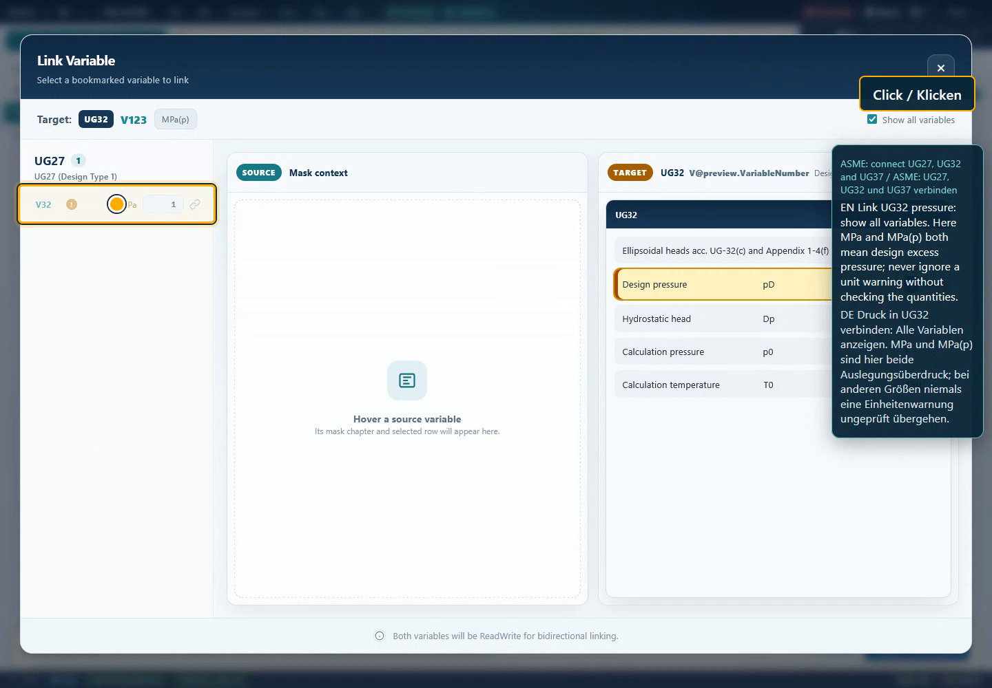
The approved historical capture below shows the common operation in an ASME example with UG27 and UG32. It illustrates selecting and checking a link, not an ER mask or an EN13480 result. Identifiers, values and units visible in the image belong to that ASME case. Use this chapter's field mapping for the piping case.
 123
123- 1. The source is a bookmarked variable from a specific chapter. Check component, meaning and unit; a visible unit warning must not be dismissed merely because numbers look similar.
- 2. The target shows module, variable number and unit. This is where you prevent mismatches such as ER09 V4 instead of V31 or ER11 V11 instead of V12.
- 3. The historical dialog describes a bidirectional ReadWrite link. A preferred editing location in the work plan therefore does not automatically enforce one-way propagation. Observe actual updates in your own copy.
Chapter 15Pipe bends, segmental bends and reducers
The ER64 entry displayed as ER06 contains six main selections. “Straight pipes and pipe bends” branches further by construction. A bend distinguishes intrados and extrados. Ordered thicknesses V47/V46 differ from available analysis thicknesses V49/V48 and required thicknesses V11/V12. Bend radius or manufactured wall distribution is an additional real input, not a property automatically known from the straight pipe.
Also check out-of-roundness: the source reference identifies V51 as 200·(do,max−do,min)/(do,max+do,min), a percentage. That differs from the absolute difference between two diameters. Establish measurement basis and unit before comparing a measured value with allowable out-of-roundness. Increasing nominal wall alone does not establish that an unsuitable bend shape becomes acceptable.
The second archived ER64 test specification addresses a segmental bend: main selection V130=2, additional selection V131=2, D₀=200 mm, nominal wall 5 mm, total allowance 0.3 mm, radius parameter V10=500 mm, mitre angle V58=20°, operating pressure 2 bar and test pressure 3 bar. Here V59 is half the angle in radians, approximately 0.17453292 rad. V60=195.3 mm denotes mean pipe diameter; test expectations give V65≈70.94516 mm for minimum constant-thickness length and V66≈241.78204 mm for minimum allowable bend radius.
These are archived test expectations for a different variant. They were not newly confirmed in the solver for this edition. Pressure results V31/V32 and V63/V64 belong to different source conditions for operation and testing. Do not combine them into an arbitrary “maximum pressure” without selecting the actual mitre arrangement. Changing from straight pipe to segmental bend already adds geometry conditions to the assessment.
For conical shells and reducers, select large end without knuckle, large end with knuckle or small end according to construction. Cone angle, transition, adjacent cylindrical thickness, cone thickness and effective connection lengths also matter. One end can need different checks from the other. Document both reducer connections instead of changing only the main diameter and reusing the straight-pipe case.
Back to top ↑Chapter 16Placing WA10, WA11 and WA07 in context
The three WA entries belong to the configured package map, but their inspected module metadata identify DIN EN 12952-3:2023-01. Preserve that code attribution in chapter titles, project notes and result comparisons. Shared package licensing or similar geometry is not a technical reason to silently interchange results from different methods.
WA10 – ends and spherical shells: Starting points are temperature V3, calculation pressure V4, outside diameter V39, ordered wall V41 and head material V46. Negative thickness deviation V47 and corrosion/wear allowance V48 remain separate. V54 describes required head thickness without allowances, while V65 gives available thickness in the source definition. Openings require additional branch, position and reinforcement data. The module description explicitly limits its scope: effects of external forces and moments are not completed by this assessment.
WA11 – pipes: The module addresses straight pipes and pipe bends. Input numbering differs from ER64: temperature V4, pressure V5, material strength V7, factor V8, allowable stress V9 and ordered wall V14. V17/V18 identify diameters without allowances in the respective source definition. Check those geometry definitions in any comparison instead of automatically connecting apparently identical labels. The source distinguishes pipe, bend and butt-weld conditions.
WA07 / WA7 – drums and headers: Metadata describe cylindrical shells under internal pressure. The field source distinguishes available thickness without allowances V7, required thickness including allowances V13 and excluding allowances V18. Additional external longitudinal loads and bending moments have separate quantities. However, neither of the two inspected Web module registries contains a standalone WA7 registration. Package membership and source availability therefore do not prove a directly available standalone launch; check actual deployment in your application.
Archived regression specifications exist for WA10 and WA11. Their existence demonstrates intended cases, not execution for this edition or agreement with ER64. A meaningful engineering comparison would align code basis, material state, every allowance definition, diameter reference and load case individually, then document remaining method differences.
Back to top ↑Chapter 17Reviewing material, temperature and time basis
The core example uses archived material designation 1232 / 1.4571(P) together with explicitly specified strength properties. The 218 MPa operating and 260 MPa test strengths belong to this teaching case. They are not a general material table for every supply condition or product made from 1.4571. Likewise, factors 1.5 and 1.05 are documented input values, not general code requirements derived here.
For an actual component, check product form, thickness, temperature, delivery and heat-treatment condition, and the property basis selected in the module. An identical short material name for pipe, end, branch and attachment does not automatically mean identical governing strength. A branch material property must not become the shell property merely because both data sheets display the same material number.
ER64 derives allowable stresses V14 and V25 from strength and factor. The inspected source logic also contains V39 for time-dependent allowable stress. The starting test sets it to N. Changing temperature while retaining explicitly specified strength initially changes only the temperature input; it does not prove automatic reassessment of material strength. Check which quantities are actually computed from material evaluation and which remain fixed in the example.
Make a temperature study a separate experiment: save starting data, check the material basis and free strength fields, change temperature, record property/stress changes, and only then compare thicknesses or pressure limits. ER09 also needs temperature-dependent stiffness for stability; ER11 has separate considerations for time-dependent design stresses and thermal expansion. Reusing a constant allowable stress explains its influence but does not replace correct material evaluation.
Back to top ↑Chapter 18Explaining the engineering result
A result report should answer a specific question: which condition limits which component in which state? For the straight teaching pipe, test thickness demand initially exceeds operating demand. The pressure revision reverses that order. Available analysis thickness remains 4.7 mm. The simple source branch therefore has a large calculated thickness margin while additional components and loads remain open.
The 200 mm hemispherical end has a smaller required thickness than the straight pipe in the operating branch considered. This supports only a statement about those two selected relationships under the same stress and geometry assumptions. The ER07 pressure derived from available wall is a different result direction from thickness demand for prescribed pressure. They need not be interchangeable by naive division: differing diameter references and branches still matter.
Maintain a component/load-case list: R1 internal pressure in operation and testing; E1 internal-pressure closure with the complete variant still to be checked separately; B1 opening with its own connection geometry; R1 external pressure with separate length and stiffness; T1 attachment with load groups. Mark entries accurately as analytically considered, compared with archived test expectations or still requiring calculation. An empty additional load case is not completed by a favourable R1 result.
Compare utilisations by definition. A stress ratio, thickness ratio and ratio of applied to allowable pressure answer related but different questions. Check denominator, unit, load combination and associated applicability conditions. ER08 V85 means utilisation; the older English “Joint Efficiency” wording in parts of the source must not be interpreted as weld factor.
A sound explanation also identifies sensitivity: higher pressure increases operating demand in the branch considered; higher allowance reduces available analysis thickness and increases the nominal-wall requirement; another unsupported length can change external-pressure conditions; different connection loads can make ER11 govern. These relationships explain which change to investigate first. Engineering acceptance then requires the actual complete project assessments.
Back to top ↑Chapter 19Saving variants and reopening them traceably
Name your own chapters by component and case, for example “R1 – straight pipe – operation/testing”, “E1 – hemispherical end – operation” and “T1 – guide – load set A”. Also record the selected construction and actual module identifier. Intent remains readable even though ER64 appears as ER06 in selection.
Save your own state before a significant change. Documentation includes inputs with units, fixed/free states, material selection, result conditions and existing links. A list of bare numbers cannot explain contradictory specifications or a different construction. The local learning data sheet is deliberately a readable JSON data collection; it is not a SOL project file and cannot be imported as a verified calculation project.
After building the case yourself in the application, save it through the normal project function. Open the file in a new session of your own and compare module count, constructions, pressure units, allowances, shared geometry, properties and governing result groups. Then change a linked quantity in a copy to check preservation of connections as well. A successful file download alone does not establish that roundtrip.
No new EN13480 save/reopen execution was performed for this edition. Frozen source and test-expectation snapshots make the book's figures traceable but do not replace project-specific file verification. Retain the date, visible application/module version and observed results for your own executed experiments.
Back to top ↑Chapter 20Troubleshooting systematically
Start with your own copy and change one cause at a time. Record expected response and actual observed state. These situations relate common operating errors to the specific field differences in this package.
I cannot find ER64 in selection.
Also search for ER06 and the straight-pipe/pipe-bend task. The package identifier is ER64, while inspected metadata show ER06 as display name. Do not infer unrelated aliases.
Why is WA07 missing despite package membership?
Neither inspected Web registry contains a standalone WA7 entry. Package membership and source availability do not guarantee a directly launchable Web component. Check the actual deployment.
Are WA10 and WA11 EN 13480 calculations?
Their module sources identify DIN EN 12952-3:2023-01. Preserve that basis explicitly. Placement in the same package does not change the engineering method.
Pressure is wrong by a factor of ten.
In ER64, check pairs V61/V4 and V62/V21. 1 bar equals 0.1 MPa. Record the transferred value with its unit and avoid contradictory fixed conversion quantities.
Required wall is extremely small.
Teaching pressure is low. The result explains a limited pressure branch and is not a manufacturing recommendation. Minimum requirements, additional loads, geometry conditions and other cases require separate assessment.
Why is available wall 4.7 rather than 5 mm?
5 mm is the final nominal wall. Negative tolerance is 0.3 mm and the other teaching allowances are zero. The source relationship gives 4.7 mm analysis thickness.
Why is inside diameter 190.6 rather than 190 mm?
The explained analysis branch uses available analysis thickness: 200−2·4.7=190.6 mm. Nominal geometry with 5 mm wall would give 190 mm. Distinguish drawing and analysis references.
Which ER64 thickness should I compare with nominal wall?
In the straight teaching branch, compare V30 including allowances with V16. Alternatively compare V33 excluding allowances with V24. V22 alone does not yet include the larger test thickness demand in the initial case.
Why does the final result not rise by 50%?
The pressure revision affects operating demand. Test data and allowances stay constant in the experiment, and the maximum selection changes from testing to operation. Required nominal wall therefore does not scale linearly by the overall factor.
Does V25 mean the same in ER64 and ER07?
No. ER64 V25 is test allowable stress; ER07 V25 is mean diameter. A link based on matching numbers would be physically incorrect.
Can ER64 V27 be used as the pipe pressure limit?
The inspected branch assigns V27 to the cone. Do not use it as a universal straight-pipe result. The algebraic inversion explained here is explicitly a separate, limited source check.
What is missing for a complete branch case?
In addition to pipe diameter and pressure, you need actual branch geometry, wall and material data, available lengths, position and any reinforcement. A 200 mm main-pipe diameter does not define a unique opening utilisation.
ER08 V85 is called “Joint Efficiency” in English.
For the source meaning discussed, V85 is utilisation. Do not treat it as weld factor. Check the result context and current label; this handbook documents the older naming discrepancy.
ER09 shows a wrong strength property after pressure transfer.
ER09 V4 is proof strength, not pressure. Required external pressure is V31. Correct the mapping in your own copy and check whether an incorrect link remains.
Can I simply use 0.1 MPa for every external-pressure case?
The value must come from the actual operating/design task. Internal and external pressure are independent loading directions. Length, temperature, stiffness and boundary conditions belong to the external-pressure case.
An ER11 moment produces an unexpectedly high stress.
First check unit, reference point and component. N·m and N·mm differ by a factor of 1000. Then check pipe/attachment dimensions, weld construction and selected load group.
Temperature rises but allowable stress stays unchanged.
Strength may be specified in the test case. Check fixed/free states of strength and factor, plus the selected material-evaluation route. A temperature value alone does not guarantee recalculated properties.
Why does inverse calculation not run directly?
Algebraic invertibility of a source branch does not prove an implemented solver direction. Check whether an input has been released and the target validly specified. If needed, use a documented parameter study and identify the method.
Is there a verified SOL file to import?
Not for this new EN13480 learning case. The downloadable sheet is JSON with explicit teaching assumptions. Archived regression specifications are source artifacts, not projects presented as completed verified SOL sessions.
What does handbook verification actually confirm?
Checks cover source identities, selected independent arithmetic, content, language alignment and static usability. This is not a newly executed engine validation of all eight modules or a complete project assessment.
Chapter 21Using terminology consistently
| Term | Meaning in the workflow |
|---|---|
| Final / ordered wall | Actual specified nominal dimension before the respective allowance deduction. |
| Available analysis thickness | Wall contribution used for the selected assessment after applicable deductions. |
| Required thickness | Calculated demand; always identify allowance inclusion and load case. |
| Governing case | The condition limiting the comparison considered; it can change after revisions. |
| Internal / external pressure | Separate loading directions with their own assessments. |
| Effective length | Length contribution credited in the assessment; not automatically the whole available length. |
| Manual data transfer | Deliberately entering data into another chapter and checking agreement. |
| Software link | Explicit relation between matching variables; actual propagation must be observed. |
| Subcalculation | Further calculation or child chapter initiated by the module. |
| Test expectation | Stored target value in a test specification; existence alone does not prove a current execution. |
Chapter 22Field reference for entry and result review
This curated selection covers 109 fields. Numbers come from inspected label sources and meanings are explained for their respective components. Outdated or untranslated source wording is not adopted as new English terminology. This is not a complete catalogue of internal helper fields. Always check the visible unit and effective input/result role in your current construction.
ER06 / ER64
| Field | Meaning | Working note |
|---|---|---|
ER64:V3 | Operating temperature | °C; separately check material-property dependency. |
ER64:V4 | Operating pressure | MPa; conversion from V61. |
ER64:V6 | Negative thickness tolerance | mm; distinct allowance cause. |
ER64:V7 | Corrosion allowance | mm; avoid deducting an already accounted allowance twice. |
ER64:V8 | Manufacturing/forming allowance | mm; additional to V6/V7. |
ER64:V9 | Total allowance | Sum V6+V7+V8. |
ER64:V14 | Operating allowable stress | MPa; V19/V20 here. |
ER64:V15 | Analysis inside diameter | Straight pipe; note source reference to analysis wall. |
ER64:V16 | Final wall thickness | mm; teaching case 5. |
ER64:V21 | Test pressure | MPa; conversion from V62. |
ER64:V22 | Required operating thickness | mm; excluding allowances, straight-pipe branch. |
ER64:V23 | Weld factor | Dimensionless; operation in teaching branch. |
ER64:V24 | Available analysis thickness | V16−V9; 4.7 mm here. |
ER64:V25 | Test allowable stress | MPa; not a diameter. |
ER64:V26 | Pipe outside diameter | mm; teaching case 200. |
ER64:V27 | Allowable operating pressure in cone branch | Not a universal straight-pipe maximum pressure. |
ER64:V28 | Required test thickness | mm; excluding allowances. |
ER64:V30 | Governing thickness including allowances | Straight pipe: max(V22,V28)+V9. |
ER64:V33 | Governing thickness excluding allowances | Straight pipe: max(V22,V28). |
ER64:V35 | Pipe/bend construction | 1 means straight in archived starting case. |
ER64:V39 | Time-dependent allowable stress | J/N selection; teaching case N. |
ER64:V58 | Mitre angle | Degrees; segmental bend. |
ER64:V60 | Mean pipe diameter | D₀−ea; segmental-bend reference. |
ER64:V61 | Operating pressure in bar | 1 bar = 0.1 MPa. |
ER64:V62 | Test pressure in bar | Separate test load case. |
ER64:V130 | Main construction | Pipe/bend, segmental bend, cone, reducer connections. |
ER07
| Field | Meaning | Working note |
|---|---|---|
ER07:V3 | Operating temperature | °C; own material basis. |
ER07:V4 | Operating internal pressure | MPa; teaching case 0.1→0.15. |
ER07:V5 | Material | Check product form and property evaluation. |
ER07:V6 | Negative tolerance | mm; distinct from forming thinning. |
ER07:V7 | Corrosion allowance | mm; separate quantity. |
ER07:V8 | Forming allowance | mm; separate from V6. |
ER07:V9 | Total allowance | mm; sum of allowances. |
ER07:V14 | Allowable stress | MPa; 218/1.5 here. |
ER07:V15 | Analysis inside diameter | mm; D₀−2ea in hemisphere branch. |
ER07:V16 | Final wall | mm; distinguish from demand. |
ER07:V22 | Required thickness without allowances | mm; operating hemisphere branch explained. |
ER07:V23 | Weld factor | Dimensionless. |
ER07:V24 | Available analysis thickness | mm; final wall minus allowances. |
ER07:V25 | Mean diameter | mm; different meaning from ER64 V25. |
ER07:V26 | Outside diameter | mm; shared connection dimension in teaching case. |
ER07:V27 | Maximum allowable pressure | MPa; selected construction and conditions apply. |
ER07:V59 | Required thickness including allowances | mm; distinguish from V22. |
ER07:V199 | Main construction | 1 hemisphere, 2 torispherical, 3 elliptical, 4–6 flat ends. |
ER08
| Field | Meaning | Working note |
|---|---|---|
ER08:V3 | Design temperature | °C; assign to the pressure case considered. |
ER08:V4 | Design internal pressure | MPa; not external loading. |
ER08:V5 | Shell material | Branch and reinforcement have their own material fields. |
ER08:V6 | Negative tolerance | mm; check shell reference. |
ER08:V7 | Corrosion allowance | mm; separate allowance. |
ER08:V8 | Thinning/forming allowance | mm; distinguish cause from V6. |
ER08:V30 | Allowable shell stress | MPa; material/temperature reference. |
ER08:V31 | Shell outside diameter | mm; matching pipe connection dimension. |
ER08:V34 | Branch outside diameter | mm; do not connect to main pipe diameter. |
ER08:V35 | Branch inside diameter | mm; own wall reference. |
ER08:V50 | Nominal shell wall | mm; pipe wall in the data plan. |
ER08:V51 | Shell analysis thickness | mm; available rather than ordered wall. |
ER08:V61 | Available connection length | mm; actual geometry. |
ER08:V62 | Effective connection length | mm; not all available length is effective. |
ER08:V65 | Maximum effective length | mm; limitation in source definition. |
ER08:V75 | Maximum calculation pressure | MPa; result for the selected opening case. |
ER08:V85 | Utilisation | Not weld efficiency despite older English label. |
ER08:V281 | Main construction | Single/Y, adjacent or rib reinforcement. |
ER09
| Field | Meaning | Working note |
|---|---|---|
ER09:V3 | Pipe elastic limit | Strength quantity; pressure direction remains separate. |
ER09:V4 | 0.2% proof strength at temperature | MPa; not an operating pressure field. |
ER09:V8 | Mean pipe radius | mm; distinguish radius from diameter. |
ER09:V13 | Pipe elastic modulus | Stiffness at governing temperature. |
ER09:V14 | Stiffener elastic modulus | Separate material reference. |
ER09:V16 | Pipe analysis thickness | mm; do not overwrite directly with nominal wall. |
ER09:V21 | Unsupported unstiffened length | mm; independent boundary condition. |
ER09:V22 | Safety factor | Check source/construction reference. |
ER09:V23 | Theoretical elastic buckling pressure | Not automatically allowable external pressure. |
ER09:V31 | Required design external pressure | Separate load case; do not copy internal pressure. |
ER09:V74 | Design temperature | °C; property and stiffness reference. |
ER09:V75 | Corrosion/erosion allowance | mm; pipe reference. |
ER09:V76 | Pipe negative tolerance | mm; separate from stiffener V79. |
ER09:V84 | Nominal wall in drawing | mm; appropriate geometry-plan quantity. |
ER09:V235 | Main construction | Pipe/bend, reducer or head. |
ER11
| Field | Meaning | Working note |
|---|---|---|
ER11:V5 | Calculation temperature | °C; separate load-case attribution. |
ER11:V11 | Attachment outside diameter | mm; not pipe outside diameter. |
ER11:V12 | Pipe outside diameter | mm; shared R1 geometry. |
ER11:V13 | Nominal pipe wall | mm; attachment wall is V14. |
ER11:V14 | Nominal attachment wall | mm; independent attachment geometry. |
ER11:V18 | Stress for flexibility analysis | Minimum of the associated design stresses. |
ER11:V21 | Longitudinal bending moment ML | Record direction, reference point and mask unit. |
ER11:V22 | Circumferential bending moment MN | Do not assign by sign alone. |
ER11:V23 | Torsional moment MT | Distinct from a bending-moment component. |
ER11:V24 | Calculation pressure Pc | Pressure quantity appropriate to the case. |
ER11:V25 | Circumferential transverse load Q1 | Separate force component. |
ER11:V26 | Longitudinal transverse load Q2 | Document coordinate system. |
ER11:V28 | Axial load W | Record attachment reference. |
ER11:V53 | Weld selection | Match actual construction. |
ER11:V85 | Attachment shape | Appropriate geometry variant. |
ER11:V86 | Stress from sustained loads | One result group only. |
ER11:V95 | Stress from restrained thermal expansion | Separate loading and assessment basis. |
WA10
| Field | Meaning | Working note |
|---|---|---|
WA10:V3 | Temperature | EN 12952-3 task. |
WA10:V4 | Calculation pressure | Separate code basis. |
WA10:V39 | Outside diameter | Head/spherical-shell reference. |
WA10:V41 | Ordered wall | Distinguish from demand and allowances. |
WA10:V54 | Required head thickness excluding allowances | Also assess openings and construction. |
WA11
| Field | Meaning | Working note |
|---|---|---|
WA11:V4 | Temperature | Not pressure as in ER64 V4. |
WA11:V5 | Calculation pressure | EN 12952-3 basis. |
WA11:V9 | Allowable stress | Check strength and factor. |
WA11:V14 | Ordered wall | Own diameter/allowance reference. |
WA11:V23 | Minimum wall e−c1 | Do not equate automatically with subtraction of every allowance. |
WA07 / WA7
| Field | Meaning | Working note |
|---|---|---|
WA7:V7 | Available thickness excluding allowances | Source reference; standalone launch not established. |
WA7:V13 | Required thickness including allowances | Cylindrical shell under WA source definition. |
WA7:V17 | Temperature | Separate material evaluation. |
WA7:V18 | Required thickness excluding allowances | Distinguish from V13. |
WA7:V21 | Allowable stress | EN 12952-3 basis. |
Chapter 23Sources, evidence status and continuation
This edition was assembled on 7 September 2026 from the project's Web sources (main13.0, 1cd12e8b173ba72aa5c95c98a14772b7ee537997) and module sources in All-Dev (fix-iteration/v10, 40606b705b2df95e550ffef5e98ab733ccc66229). The source snapshot contains paths, SHA-256 hashes, package descriptions, main variants and labels. Inspected source paths had no reported local changes when collected. This does not identify any currently loaded plugin binary.
Engineering review particularly covered ER64 pressure conversion, property evaluation, allowance summation, available wall and straight-pipe operating/test pressure branches, plus the ER07 hemisphere branch. Field, mask and module sources support the additional setup and assessment chapters. Source code also contains ER08 child-chapter routes; no new Web execution is claimed.
The archived regression-specification evidence list documents 9 files for ER64, ER07, ER09, ER11, WA10 and WA11. A stored expected value and expected calculation success do not constitute an executed test log. Each createdAt comes from its file and is not an independently verified recording date. The straight ER64 case and a separate 500 mm hemisphere supply selected comparison values for independent source arithmetic.
The handbook's arithmetic tests compare these selected figures and check pressure revision, case switching and algebraic inversion. No calculation service was started and no new EN13480 session created for them. Evidence level is therefore source-only. Five unaltered program symbols illustrate tasks. The authored concept diagram depicts a data plan. Both are explicitly distinct from runtime screenshots.
Linked DIN/NEN product pages were checked to identify code name, edition and scope. The full code text is neither reproduced here nor presented as fully reviewed. An updated module designation alone does not prove every individual equation or every program branch's conformity to an edition.
A later runtime supplement still requires an owned cold start, complete valid ER08/ER09/ER11 cases, observed links, variant comparison, save/reopen and real annotated program captures. This book provides traceable starting data, field mappings and assessment criteria for that work. Neither those pending runtime checks nor eight complete individual-module manuals are represented as finished.
Back to top ↑